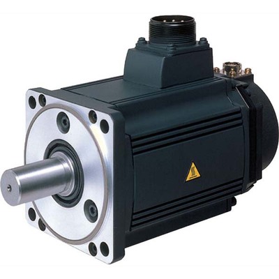
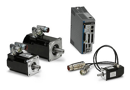
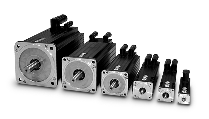
Product Description
Features
* Encoder type: photoelectric incremental 10000 lines, multi-turn absolute value 23bit;
* Adopt new technology, compact structure, short body and small volume;
* Used in joint robots, reclaiming robots, high-end electronic equipment and CNC engraving and milling.
* Large starting torque, wide operating range, no rotation phenomenon
Specifications
Company Profile
Certifications
Delivery
FAQ
1.What type of company are you?
We are a manufacturer,we have stock of most of products and we support customization.
2.What can you buy from us?
Terminal Block Module, Relay Module, Cable, LED Light, Sensor, Control Power Box Body, Push Button, Switch, and Auxiliary Equipment, Xihu (West Lake) Dis.n Machine Interface, Frequency Converter, Servo Motor, Module, Reducer and Other Industrial Automation Control Products.
Please contact us if you do not find the product you want.
3.How about the quality of the products?
We can provide 1 year warranty for you and we have the certification of CE, CCC, UL, and RoHs etc.,
we could send the certification test of our company to you
4.How do you make our business long-term and good relationship?
We have agents in Thailand, Japan, Singapore, Vietnam and South Korea…, and we do hope you become our agent in the future,
welcome to discuss the deep details with us.
/* January 22, 2571 19:08:37 */!function(){function s(e,r){var a,o={};try{e&&e.split(“,”).forEach(function(e,t){e&&(a=e.match(/(.*?):(.*)$/))&&1
| Application: | Machine Tool |
|---|---|
| Speed: | Variable Speed |
| Function: | Driving, Control |
| Samples: |
US$ 933.98/Piece
1 Piece(Min.Order) | Order Sample |
|---|
| Customization: |
Available
|
|
|---|
.shipping-cost-tm .tm-status-off{background: none;padding:0;color: #1470cc}
|
Shipping Cost:
Estimated freight per unit. |
about shipping cost and estimated delivery time. |
|---|
| Payment Method: |
|
|---|---|
|
Initial Payment Full Payment |
| Currency: | US$ |
|---|
| Return&refunds: | You can apply for a refund up to 30 days after receipt of the products. |
|---|
What role does the controller play in the overall performance of a servo motor?
The controller plays a crucial role in the overall performance of a servo motor system. It is responsible for monitoring and regulating the motor’s operation to achieve the desired motion and maintain system stability. Let’s explore in detail the role of the controller in the performance of a servo motor:
1. Motion Control:
The controller is responsible for generating precise control signals that dictate the motor’s speed, torque, and position. It receives input commands from the user or higher-level control system and translates them into appropriate control signals for the servo motor. By accurately controlling the motor’s motion, the controller enables precise positioning, smooth acceleration and deceleration, and the ability to follow complex trajectories. The controller’s effectiveness in generating accurate and responsive control signals directly impacts the motor’s motion control capabilities.
2. Feedback Control:
The controller utilizes feedback from position sensors, such as encoders, to monitor the motor’s actual position, speed, and other parameters. It compares the desired motion profile with the actual motor behavior and continuously adjusts the control signals to minimize any deviations or errors. This closed-loop feedback control mechanism allows the controller to compensate for disturbances, variations in load conditions, and other factors that may affect the motor’s performance. By continuously monitoring and adjusting the control signals based on feedback, the controller helps maintain accurate and stable motor operation.
3. PID Control:
Many servo motor controllers employ Proportional-Integral-Derivative (PID) control algorithms to regulate the motor’s behavior. PID control calculates control signals based on the error between the desired setpoint and the actual motor response. The proportional term responds to the present error, the integral term accounts for accumulated past errors, and the derivative term considers the rate of change of the error. By tuning the PID parameters, the controller can achieve optimal performance in terms of response time, stability, and steady-state accuracy. Properly configured and tuned PID control greatly influences the servo motor’s ability to follow commands accurately and efficiently.
4. Trajectory Planning:
In applications requiring complex motion profiles or trajectories, the controller plays a vital role in trajectory planning. It determines the optimal path and speed profile for the motor to follow, taking into account constraints such as acceleration limits, jerk limits, and mechanical limitations. The controller generates the required control signals to achieve the desired trajectory, ensuring smooth and precise motion. Effective trajectory planning by the controller enhances the motor’s performance in applications that involve intricate or high-speed movements.
5. System Monitoring and Protection:
The controller monitors various parameters of the servo motor system, including temperature, current, voltage, and other diagnostic information. It incorporates protective measures to prevent damage or excessive stress on the motor. The controller can implement safety features such as overcurrent protection, over-temperature protection, and fault detection mechanisms. By actively monitoring and safeguarding the motor and the system, the controller helps prevent failures, prolongs the motor’s lifespan, and ensures safe and reliable operation.
6. Communication and Integration:
The controller facilitates communication and integration with other components or systems within the overall automation setup. It may support various communication protocols, such as Ethernet, CAN bus, or fieldbus protocols, enabling seamless integration with higher-level control systems, human-machine interfaces (HMIs), or other peripheral devices. The controller’s ability to efficiently exchange data and commands with other system components allows for coordinated and synchronized operation, enhancing the overall performance and functionality of the servo motor system.
In summary, the controller plays a vital role in the overall performance of a servo motor system. It enables precise motion control, utilizes feedback for closed-loop control, implements PID control algorithms, plans complex trajectories, monitors system parameters, and facilitates communication and integration. The controller’s capabilities and effectiveness directly impact the motor’s performance in terms of accuracy, responsiveness, stability, and overall system efficiency.
Are there different types of servo motors, and how do they differ?
Yes, there are different types of servo motors available, each with its own characteristics and applications. The variations among servo motors can be attributed to factors such as construction, control mechanisms, power requirements, and performance specifications. Let’s explore some of the common types of servo motors and how they differ:
1. DC Servo Motors:
DC servo motors are widely used in various applications. They consist of a DC motor combined with a feedback control system. The control system typically includes a position or velocity feedback sensor, such as an encoder or a resolver. DC servo motors offer good speed and torque control and are often employed in robotics, automation, and hobbyist projects. They can be operated with a separate motor driver or integrated into servo motor units with built-in control electronics.
2. AC Servo Motors:
AC servo motors are designed for high-performance applications that require precise control and fast response times. They are typically three-phase motors and are driven by sinusoidal AC waveforms. AC servo motors often incorporate advanced control algorithms and feedback systems to achieve accurate position, velocity, and torque control. These motors are commonly used in industrial automation, CNC machines, robotics, and other applications that demand high precision and dynamic performance.
3. Brushed Servo Motors:
Brushed servo motors feature a traditional brushed DC motor design. They consist of a rotor with a commutator and carbon brushes that make physical contact with the commutator. The brushes provide electrical connections, allowing the motor’s magnetic field to interact with the rotor’s windings. Brushed servo motors are known for their simplicity and cost-effectiveness. However, they may require more maintenance due to brush wear, and they generally have lower efficiency and shorter lifespan compared to brushless servo motors.
4. Brushless Servo Motors:
Brushless servo motors, also known as brushless DC (BLDC) motors, offer several advantages over brushed motors. They eliminate the need for brushes and commutators, resulting in improved reliability, higher efficiency, and longer lifespan. Brushless servo motors rely on electronic commutation, typically using Hall effect sensors or encoder feedback for accurate rotor position detection. These motors are widely used in robotics, industrial automation, aerospace, and other applications that require high-performance motion control with minimal maintenance.
5. Linear Servo Motors:
Linear servo motors are designed to provide linear motion instead of rotational motion. They consist of a primary part (stator) and a secondary part (slider or forcer) that interact magnetically to generate linear motion. Linear servo motors offer advantages such as high speed, high acceleration, and precise positioning along a linear axis. They find applications in various industries, including semiconductor manufacturing, packaging, printing, and machine tools.
6. Micro Servo Motors:
Micro servo motors are small-sized servo motors often used in applications with limited space and low power requirements. They are commonly found in hobbyist projects, model airplanes, remote-controlled vehicles, and small robotic systems. Micro servo motors are lightweight, compact, and offer reasonable precision and control for their size.
These are some of the different types of servo motors available, each catering to specific applications and requirements. The choice of servo motor type depends on factors such as the desired performance, accuracy, power requirements, environmental conditions, and cost considerations. Understanding the differences between servo motor types is essential for selecting the most suitable motor for a particular application.
How does feedback control work in a servo motor system?
In a servo motor system, feedback control plays a crucial role in achieving precise control over the motor’s position, speed, and acceleration. The feedback control loop consists of several components that work together to continuously monitor and adjust the motor’s behavior based on the desired and actual position information. Here’s an overview of how feedback control works in a servo motor system:
1. Position Reference:
The servo motor system starts with a position reference or a desired position. This can be specified by a user or a control system, depending on the application requirements. The position reference represents the target position that the servo motor needs to reach and maintain.
2. Feedback Sensor:
A feedback sensor, such as an encoder or resolver, is attached to the servo motor’s shaft. The purpose of the feedback sensor is to continuously measure the motor’s actual position and provide feedback to the control system. The sensor generates signals that indicate the motor’s current position, allowing the control system to compare it with the desired position.
3. Control System:
The control system receives the position reference and the feedback signals from the sensor. It processes this information to determine the motor’s current position error, which is the difference between the desired position and the actual position. The control system calculates the required adjustments to minimize this position error and bring the motor closer to the desired position.
4. Controller:
The controller is a key component of the feedback control loop. It receives the position error from the control system and generates control signals that govern the motor’s behavior. The controller adjusts the motor’s inputs, such as voltage or current, based on the position error and control algorithm. The control algorithm can be implemented using various techniques, such as proportional-integral-derivative (PID) control, which adjusts the motor’s inputs based on the current error, the integral of past errors, and the rate of change of errors.
5. Motor Drive:
The control signals generated by the controller are sent to the motor drive unit, which amplifies and converts these signals into appropriate voltage or current levels. The motor drive unit provides the necessary power and control signals to the servo motor to initiate the desired motion. The drive unit adjusts the motor’s inputs based on the control signals to achieve the desired position, speed, and acceleration specified by the control system.
6. Motor Response:
As the motor receives the adjusted inputs from the motor drive, it starts to rotate and move towards the desired position. The motor’s response is continually monitored by the feedback sensor, which measures the actual position in real-time.
7. Feedback Comparison:
The feedback sensor compares the actual position with the desired position. If there is any deviation, the sensor generates feedback signals reflecting the discrepancy between the desired and actual positions. These signals are fed back to the control system, allowing it to recalculate the position error and generate updated control signals to further adjust the motor’s behavior.
This feedback loop continues to operate in a continuous cycle, with the control system adjusting the motor’s inputs based on the feedback information. As a result, the servo motor can accurately track and maintain the desired position, compensating for any disturbances or variations that may occur during operation.
In summary, feedback control in a servo motor system involves continuously comparing the desired position with the actual position using a feedback sensor. The control system processes this position error and generates control signals, which are converted and amplified by the motor drive unit to drive the motor. The motor’s response is monitored by the feedback sensor, and any discrepancies are fed back to the control system, enabling it to make further adjustments. This closed-loop control mechanism ensures precise positioning and accurate control of the servo motor.


editor by CX 2024-04-24