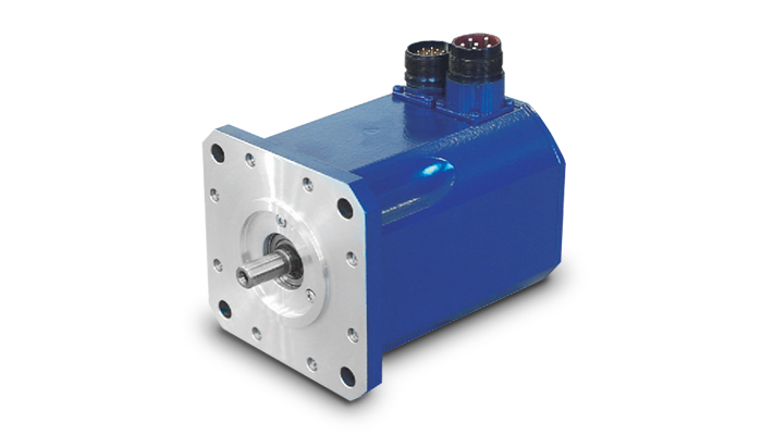
Product Description
Model:S/SA/SAF/SF37-97
Ratio:9.96-244.74
Input Power:0.18KW-22KW.
Permissible Torque:up to 4000N.m
Mounting Mode: foot-mounted, flange-mounted, input shaft or with various types of motor direct
Company Introduction
Get the right gearbox for your equipment.
PTT knows gearbox. As the leading industry gearbox manufacturer, PSS offers the best power transmission solutions to perfectly meet your specific industry application. On gearbox, CZPT has a lot more to share.
We always satisfy all industries with our gearbox
PTT strives for 100% satisfaction from customers of all industries. We welcome challenges to offer tailored design or special solution to satisfy customers’ Special needs on applications. We like to make impossibility become possibility.
Key features
Turbine gearboxes and planetary gearboxes are our advantages. Most companies can only manufacture Helical Bevel gearboxes, and we have a strong design team that has now designed turbine gearboxes up to 70, 000 rpm.
Diversity
PTT offers a vast diversity of gear reducer, geared motor and gearbox. No doubt you are CZPT to find what you need with PTT.
Reliability
PTT is a trustworthy manufacturer you can rely on, no matter in terms of quality, delivery, pricing, service, etc. It becomes our name tag during our history of servicing our customers.
Capability
PTT is CZPT to manufacture 200, 000 sets of gear reducers yearly and keeps investing on development of new series product.
We have a large list of our satisfied clients
Among the large list of our satisfied clients, there are many trend-setting top brands in various industries.
Mian products
Helical Gear Units
Bevel-Helical Gear Units
ZYJ Series Gear Units
DY Series Gear Units
P Planetary Gear Units
MLX Series Mill Gear Units
High Speed Gear Units
Non-stand Gear Units
RFQ
Q:Are you trading company or manufacturer?
A: We are manufacturer with over 20 years’ experience.
Q: How long is your delivery time?
A: Generally it is within 10 days if the goods are in stock, for goods produced as per order, it is within 35 days after confirmation of order.
Q: How long should I wait for the feedback after I send the enquiry?
A: Normally within 12 hours.
Q: What information should I give you to confirm the product?
A: Model/Size, Transmission Ratio, Speed, Shaft directions & Order quantity etc.
Q: Hong long is your product warranty?
A: We offer 12 months warranty from departure date of the goods.
Q: What is your payment terms? T/T 100% in advance for amount less than USD10000.-, 30% T/T in advance , balance before shipment for amount above USD10000.
If you have any other questions, please feel free to contact us below:
HOW TO CONTACT US?
Send your Inquiry Details in the Below, click “Send” Now!
| Application: | Motor, Machinery, Agricultural Machinery |
|---|---|
| Function: | Change Drive Torque, Speed Changing, Speed Reduction |
| Hardness: | Hardened Tooth Surface |
| Customization: |
Available
| Customized Request |
|---|
.shipping-cost-tm .tm-status-off{background: none;padding:0;color: #1470cc}
|
Shipping Cost:
Estimated freight per unit. |
about shipping cost and estimated delivery time. |
|---|
| Payment Method: |
|
|---|---|
|
Initial Payment Full Payment |
| Currency: | US$ |
|---|
| Return&refunds: | You can apply for a refund up to 30 days after receipt of the products. |
|---|

Benefits of a Planetary Motor
Besides being one of the most efficient forms of a drive, a Planetary Motor also offers a great number of other benefits. These features enable it to create a vast range of gear reductions, as well as generate higher torques and torque density. Let’s take a closer look at the benefits this mechanism has to offer. To understand what makes it so appealing, we’ll explore the different types of planetary systems.
Solar gear
The solar gear on a planetary motor has two distinct advantages. It produces less noise and heat than a helical gear. Its compact footprint also minimizes noise. It can operate at high speeds without sacrificing efficiency. However, it must be maintained with constant care to operate efficiently. Solar gears can be easily damaged by water and other debris. Solar gears on planetary motors may need to be replaced over time.
A planetary gearbox is composed of a sun gear and two or more planetary ring and spur gears. The sun gear is the primary gear and is driven by the input shaft. The other two gears mesh with the sun gear and engage the stationary ring gear. The three gears are held together by a carrier, which sets the spacing. The output shaft then turns the planetary gears. This creates an output shaft that rotates.
Another advantage of planetary gears is that they can transfer higher torques while being compact. These advantages have led to the creation of solar gears. They can reduce the amount of energy consumed and produce more power. They also provide a longer service life. They are an excellent choice for solar-powered vehicles. But they must be installed by a certified solar energy company. And there are other advantages as well. When you install a solar gear on a planetary motor, the energy produced by the sun will be converted to useful energy.
A solar gear on a planetary motor uses a solar gear to transmit torque from the sun to the planet. This system works on the principle that the sun gear rotates at the same rate as the planet gears. The sun gear has a common design modulus of -Ns/Np. Hence, a 24-tooth sun gear equals a 3-1/2 planet gear ratio. When you consider the efficiency of solar gears on planetary motors, you will be able to determine whether the solar gears are more efficient.
Sun gear
The mechanical arrangement of a planetary motor comprises of two components: a ring gear and a sun gear. The ring gear is fixed to the motor’s output shaft, while the sun gear rolls around and orbits around it. The ring gear and sun gear are linked by a planetary carrier, and the torque they produce is distributed across their teeth. The planetary structure arrangement also reduces backlash, and is critical to achieve a quick start and stop cycle.
When the two planetary gears rotate independently, the sun gear will rotate counterclockwise and the ring-gear will turn in the same direction. The ring-gear assembly is mounted in a carrier. The carrier gear and sun gear are connected to each other by a shaft. The planetary gears and sun gear rotate around each other on the ring-gear carrier to reduce the speed of the output shaft. The planetary gear system can be multiplied or staged to obtain a higher reduction ratio.
A planetary gear motor mimics the planetary rotation system. The input shaft turns a central gear, known as the sun gear, while the planetary gears rotate around a stationary sun gear. The motor’s compact design allows it to be easily mounted to a vehicle, and its low weight makes it ideal for small vehicles. In addition to being highly efficient, a planetary gear motor also offers many other benefits.
A planetary gearbox uses a sun gear to provide torque to the other gears. The planet pinions mesh with an internal tooth ring gear to generate rotation. The carrier also acts as a hub between the input gear and output shaft. The output shaft combines these two components, giving a higher torque. There are three types of planetary gearboxes: the sun gear and a wheel drive planetary gearbox.
Planetary gear
A planetary motor gear works by distributing rotational force along a separating plate and a cylindrical shaft. A shock-absorbing device is included between the separating plate and cylindrical shaft. This depressed portion prevents abrasion wear and foreign particles from entering the device. The separating plate and shaft are positioned coaxially. In this arrangement, the input shaft and output shaft are rotated relative to one another. The rotatable disc absorbs the impact.
Another benefit of a planetary motor gear is its efficiency. Planetary motor gears are highly efficient at transferring power, with 97% of the input energy being transferred to the output. They can also have high gear ratios, and offer low noise and backlash. This design also allows the planetary gearbox to work with electric motors. In addition, planetary gears also have a long service life. The efficiency of planetary gears is due in part to the large number of teeth.
Other benefits of a planetary motor gear include the ease of changing ratios, as well as the reduced safety stock. Unlike other gears, planetary gears don’t require special tools for changing ratios. They are used in numerous industries, and share parts across multiple sizes. This means that they are cost-effective to produce and require less safety stock. They can withstand high shock and wear, and are also compact. If you’re looking for a planetary motor gear, you’ve come to the right place.
The axial end surface of a planetary gear can be worn down by abrasion with a separating plate. In addition, foreign particles may enter the planetary gear device. These particles can damage the gears or even cause noise. As a result, you should check planetary gears for damage and wear. If you’re looking for a gear, make sure it has been thoroughly tested and installed by a professional.
Planetary gearbox
A planetary motor and gearbox are a common combination of electric and mechanical power sources. They share the load of rotation between multiple gear teeth to increase the torque capacity. This design is also more rigid, with low backlash that can be as low as one or two arc minutes. The advantages of a planetary gearmotor over a conventional electric motor include compact size, high efficiency, and less risk of gear failure. Planetary gear motors are also more reliable and durable than conventional electric motors.
A planetary gearbox is designed for a single stage of reduction, or a multiple-stage unit can be built with several individual cartridges. Gear ratios may also be selected according to user preference, either to face mount the output stage or to use a 5mm hex shaft. For multi-stage planetary gearboxes, there are a variety of different options available. These include high-efficiency planetary gearboxes that achieve a 98% efficiency at single reduction. In addition, they are noiseless, and reduce heat loss.
A planetary gearbox may be used to increase torque in a robot or other automated system. There are different types of planetary gear sets available, including gearboxes with sliding or rolling sections. When choosing a planetary gearset, consider the environment and other factors such as backlash, torque, and ratio. There are many advantages to a planetary gearbox and the benefits and drawbacks associated with it.
Planetary gearboxes are similar to those in a solar system. They feature a central sun gear in the middle, two or more outer gears, and a ring gear at the output. The planetary gears rotate in a ring-like structure around a stationary sun gear. When the gears are engaged, they are connected by a carrier that is fixed to the machine’s shaft.
Planetary gear motor
Planetary gear motors reduce the rotational speed of an armature by one or more times. The reduction ratio depends on the structure of the planetary gear device. The planetary gear device has an output shaft and an armature shaft. A separating plate separates the two. The output shaft moves in a circular pattern to turn the pinion 3. When the pinion rotates to the engagement position, it is engaged with the ring gear 4. The ring gear then transmits the rotational torque to the armature shaft. The result is that the engine cranks up.
Planetary gear motors are cylindrical in shape and are available in various power levels. They are typically made of steel or brass and contain multiple gears that share the load. These motors can handle massive power transfers. The planetary gear drive, on the other hand, requires more components, such as a sun’s gear and multiple planetary gears. Consequently, it may not be suitable for all types of applications. Therefore, the planetary gear drive is generally used for more complex machines.
Brush dusts from the electric motor may enter the planetary gear device and cause it to malfunction. In addition, abrasion wear on the separating plate can affect the gear engagement of the planetary gear device. If this occurs, the gears will not engage properly and may make noise. In order to prevent such a situation from occurring, it is important to regularly inspect planetary gear motors and their abrasion-resistant separating plates.
Planetary gear motors come in many different power levels and sizes. These motors are usually cylindrical in shape and are made of steel, brass, plastic, or a combination of both materials. A planetary gear motor can be used in applications where space is an issue. This motor also allows for low gearings in small spaces. The planetary gearing allows for large amounts of power transfer. The output shaft size is dependent on the gear ratio and the motor speed.


editor by CX 2023-11-21
China manufacturer Ab60 Precision Helical Gear Planetary Reduction Machine Box 42/90/115 Stepper Servo Motor 400W 750W vacuum pump and compressor
Product Description
Product Description
Detailed Photos
Product Parameters
|
Name |
High Precision Planetary Gearbox |
|
Model |
AB042, AB060, AB060A, AB090A, AB115, AB142, AB180, AB220 |
|
Gearing Arrangement |
Planetary |
|
Effeiency withfull load |
≥97 |
|
Backlash |
≤5 |
|
Weight |
0.5~48kg |
|
Gear Type |
Helical Gear |
|
Gear stages |
1 stage, 2 stage |
|
Rated Torque |
14N.m-2000N.m |
|
Gear Ratio One-stage |
3, 4, 5, 6, 7, 8, 9, 10 |
|
Gear Ratio Two-stage |
15, 20, 25, 30, 35, 40, 45, 50, 60, 70, 80, 90, 100 |
|
Mounting Position |
Horizontal (foot mounted) or Vertical (flange mounted) |
|
Usage |
stepper motor, servo motor, AC motor, DC motor, etc |
features:
AB-series reducer features:
1. Helical gear design The reduction mechanism adopts the helical gear design, and its tooth shape meshing rate is more than twice that of the general spur gear, and has the characteristics of smooth operation, low noise, high output torque and low backlash
2. Collet type locking mechanism The connection between the input end and the motor adopts a collet-type locking mechanism and undergoes dynamic balance analysis to ensure the concentricity of the joint interface and zero-backlash power transmission at high input speeds
3. Modular design of motor connection board The unique modular design of the motor connecting plate and shaft is suitable for any brand and type of servo motor;
4. Efficient surface treatment technology The surface of the gearbox is treated with electroless nickel, and the connecting plate of the motor is treated with black anodic treatment to improve the environmental tolerance and corrosion resistance
5. One-piece gearbox body The gearbox and the inner ring gear adopt an integrated design, with compact structure, high precision and large output torque
6. Accurate concentricity of gear bar The sun gear made of the whole gear bar has strong rigidity and accurate concentricity
7. Solid, Single piece sun gear construction obtains precise concentricity with increased strength and rigidity. 8.Precision taper roller bearing support to increases radial and axial loading capacity.
Applications
Certifications
Packaging & Shipping
| Hardness: | Hardened Tooth Surface |
|---|---|
| Installation: | Vertical Type |
| Layout: | Coaxial |
| Gear Shape: | Planetary |
| Step: | Single-Step |
| Type: | Ab Series Gearbox, Gear Reducer |
| Samples: |
US$ 100/Piece
1 Piece(Min.Order) | |
|---|
How does the cost of servo motors vary based on their specifications and features?
The cost of servo motors can vary significantly based on their specifications and features. Several factors influence the price of servo motors, and understanding these factors can help in selecting the most cost-effective option for a specific application. Let’s explore in detail how the cost of servo motors can vary:
1. Power Rating:
One of the primary factors affecting the cost of a servo motor is its power rating, which is typically measured in watts or kilowatts. Higher power-rated servo motors generally cost more than lower-rated ones due to the increased materials and manufacturing required to handle higher power levels. The power rating of a servo motor is determined by the torque and speed requirements of the application. Higher torque and speed capabilities often correspond to higher costs.
2. Torque and Speed:
The torque and speed capabilities of a servo motor directly impact its cost. Servo motors designed for high torque and high-speed applications tend to be more expensive due to the need for robust construction, specialized materials, and advanced control electronics. Motors with higher torque and speed ratings often require more powerful magnets, larger windings, and higher precision components, contributing to the increase in cost.
3. Frame Size:
The physical size or frame size of a servo motor also plays a role in determining its cost. Servo motors come in various frame sizes, such as NEMA (National Electrical Manufacturers Association) standard sizes in North America. Larger frame sizes generally command higher prices due to the increased materials and manufacturing complexity required to build larger motors. Smaller frame sizes, on the other hand, may be more cost-effective but may have limitations in terms of torque and speed capabilities.
4. Feedback Mechanism:
The feedback mechanism used in a servo motor affects its cost. Servo motors typically employ encoders or resolvers to provide feedback on the rotor position. Higher-resolution encoders or more advanced feedback technologies can increase the cost of the motor. For example, servo motors with absolute encoders, which provide position information even after power loss, tend to be more expensive than those with incremental encoders.
5. Control Features and Technology:
The control features and technology incorporated into a servo motor can influence its cost. Advanced servo motors may offer features such as built-in controllers, fieldbus communication interfaces, advanced motion control algorithms, or integrated safety functions. These additional features contribute to the cost of the motor but can provide added value and convenience in certain applications. Standard servo motors with basic control functionality may be more cost-effective for simpler applications.
6. Brand and Reputation:
The brand and reputation of the servo motor manufacturer can impact its cost. Established and reputable brands often command higher prices due to factors such as quality assurance, reliability, technical support, and extensive product warranties. While motors from less-known or generic brands may be more affordable, they may not offer the same level of performance, reliability, or long-term support.
7. Customization and Application-Specific Requirements:
If a servo motor needs to meet specific customization or application-specific requirements, such as specialized mounting options, environmental sealing, or compliance with industry standards, the cost may increase. Customization often involves additional engineering, design, and manufacturing efforts, which can lead to higher prices compared to off-the-shelf servo motors.
It’s important to note that the cost of a servo motor is not the sole indicator of its quality or suitability for a particular application. It is essential to carefully evaluate the motor’s specifications, features, and performance characteristics in relation to the application requirements to make an informed decision.
In summary, the cost of servo motors varies based on factors such as power rating, torque and speed capabilities, frame size, feedback mechanism, control features and technology, brand reputation, and customization requirements. By considering these factors and comparing different options, it is possible to select a servo motor that strikes the right balance between performance and cost-effectiveness for a specific application.
Can you explain the concept of torque and speed in relation to servo motors?
Torque and speed are two essential parameters in understanding the performance characteristics of servo motors. Let’s explore these concepts in relation to servo motors:
Torque:
Torque refers to the rotational force produced by a servo motor. It determines the motor’s ability to generate rotational motion and overcome resistance or load. Torque is typically measured in units of force multiplied by distance, such as Nm (Newton-meter) or oz-in (ounce-inch).
The torque output of a servo motor is crucial in applications where the motor needs to move or control a load. The motor must provide enough torque to overcome the resistance or friction in the system and maintain the desired position or motion. Higher torque allows the motor to handle heavier loads or more challenging operating conditions.
It is important to note that the torque characteristics of a servo motor may vary depending on the speed or position of the motor. Manufacturers often provide torque-speed curves or torque-position curves, which illustrate the motor’s torque capabilities at different operating points. Understanding these curves helps in selecting a servo motor that can deliver the required torque for a specific application.
Speed:
Speed refers to the rotational velocity at which a servo motor operates. It indicates how fast the motor can rotate and how quickly it can achieve the desired position or motion. Speed is typically measured in units of revolutions per minute (RPM) or radians per second (rad/s).
The speed of a servo motor is crucial in applications that require rapid movements or high-speed operations. It determines the motor’s responsiveness and the system’s overall performance. Different servo motors have different speed capabilities, and the maximum achievable speed is often specified by the manufacturer.
It is worth noting that the speed of a servo motor may also affect its torque output. Some servo motors exhibit a phenomenon known as “speed-torque curve,” where the motor’s torque decreases as the speed increases. This behavior is influenced by factors such as motor design, winding resistance, and control algorithms. Understanding the speed-torque characteristics of a servo motor is important for selecting a motor that can meet the speed requirements of the application while maintaining sufficient torque.
Overall, torque and speed are interrelated parameters that determine the performance capabilities of a servo motor. The torque capability determines the motor’s ability to handle loads, while the speed capability determines how quickly the motor can achieve the desired motion. When selecting a servo motor, it is essential to consider both the torque and speed requirements of the application to ensure that the motor can deliver the desired performance.

What are the key advantages of using servo motors in industrial applications?
Servo motors offer several key advantages that make them highly beneficial for a wide range of industrial applications. Here are some of the main advantages of using servo motors:
1. Precise Positioning:
Servo motors excel at precise positioning control. They can accurately move to specific angles or positions with high repeatability. This level of precision is crucial in applications where accurate and consistent positioning is required, such as robotics, CNC machining, and assembly lines.
2. High Torque at Various Speeds:
Servo motors are designed to deliver high torque output across a range of speeds. They can generate significant torque even at low speeds, enabling efficient operation in applications that require both high torque and precise control, such as lifting heavy loads or performing intricate movements.
3. Fast Response Times:
Servo motors have fast response times, meaning they can quickly accelerate, decelerate, and change direction in response to control signals. This responsiveness is essential in applications where rapid and dynamic motion control is needed, such as industrial automation, robotics, and production line equipment.
4. Closed-Loop Control:
Servo motors operate in a closed-loop control system, where feedback from position sensors is continuously used to adjust the motor’s behavior. This feedback control mechanism enables accurate tracking of the desired position and compensates for any disturbances or variations that may occur during operation. It enhances the motor’s accuracy, stability, and performance.
5. Wide Range of Sizes and Power Ratings:
Servo motors are available in a wide range of sizes and power ratings, making them suitable for diverse industrial applications. Whether it’s a small motor for precision tasks or a large motor for heavy-duty operations, there are servo motor options to meet various requirements.
6. Energy Efficiency:
Servo motors are designed to be energy-efficient. They typically have high power density, which means they can deliver a significant amount of torque per unit of size and weight. This efficiency helps reduce power consumption, lowers operating costs, and contributes to a greener and more sustainable industrial environment.
7. Flexibility and Adaptability:
Due to their versatility, servo motors can be easily integrated into different systems and applications. They can be combined with various control systems, sensors, and communication protocols to provide seamless integration and compatibility with existing industrial setups. This flexibility allows for customized and scalable solutions tailored to specific industrial requirements.
8. Durability and Reliability:
Servo motors are known for their durability and reliability, even in demanding industrial environments. They are built to withstand harsh conditions such as high temperatures, vibrations, and dust. This robust construction ensures long-term operation and minimizes downtime, contributing to increased productivity and reduced maintenance costs.
In summary, the key advantages of using servo motors in industrial applications include precise positioning, high torque at various speeds, fast response times, closed-loop control for accuracy and stability, a wide range of sizes and power ratings, energy efficiency, flexibility, and durability. These advantages make servo motors highly valuable for industries that require precise motion control, such as robotics, manufacturing, automation, CNC machining, and many others.
editor by CX 2023-11-17
China Hot selling Worm Gear Box Assembly Gearbox Wheel Speed Agricultural Planetary Helical Bevel Steering Gear Drive Motor Speed motor armature
Product Description
Technical Features
The high degree of modularity is a design feature of SRC helical gearboxes range. It can be connected respectively with motors such as normal motor, brake motor, explosion-proof motor, frequency conversion motor, servo motor, IEC motor and so on. This kind of product is widely used in drive fields such as textile, foodstuff, ceramics packing, logistics, plastics and so on. It is possible to set up the version required using flanges or feet.
Products characteristics
SRC series helical gear units has more than 4 types. Power 0.12-4kw; Ratio 3.66-54; Torque max 120-500Nm. It can be connected (foot or flange) discretionary and use multi-mounting positions according to customers requirements.
Ground-hardened helical gears;
Modularity,can be combined in many forms;
Aluminium casing, light weight;
Gears in carbonize hard, durable;
Universal mounting;
Refined design,space effective and low noise
Structure feature
Model illuminate
|
1 |
Code for gear units series |
|
2 |
No F code means foot mounted.With F code B5 flange mounted.With Z code B14 flange mounted |
|
3 |
Specification code of gear units 01 |
|
4 |
I,II,III,B5 Output flange specification,default I not to write out is ok |
|
5 |
IEC: Input flange HS: shaft input |
|
6 |
Transmission ratio of gear units |
|
7 |
M1:Mounting position, default mounting position M1 not to write out is ok |
|
8 |
Position diagram for motor terminal box,default position o°(R) not to write out is ok |
|
9 |
No mark means without motor Model motor(poles of power) |
|
10 |
Voltage – frequency |
|
11 |
Coil in position for motor, default position S not to write out is ok |
4.2 Rotation speed n
n1 Gear units input speed
n2 Gear units output speed
If driven by the external gearing,1400r/min or lower rotation speed is suggested so as to optimize the working conditions and prolong the service life.Higher input rotation speed is permitted, but in this situation,the rated torque M2 will be reduced
4.5 Service factor fs
The effect of the driven machine on the gear unit is taken into account to a sufficient level of accuracy using the service factor fs. The service factor is determined according to the daily operation time and the starting frequency Z. Three load classifications are considered depending on the mass acceleration factor. You can read off the service factor applicable to your application in following figure. The service factor selected using this diagram must be less than or equal to the service factor as given in the performance parameter table.
* starting frequency Z: The cycles include all starting and braking procedures as well as change overs from low to high speed
SRC02..(HS) Performance parameter
|
kw |
Output speed |
Torque |
Speed ratio |
fs |
Model |
IEC |
|
0.37 |
16.7rpm |
204N.M |
54 |
1.0 |
SRC02 |
80B5/B14
|
Helical gearbox outline dimension heet
| Foot Code | U | V | V1 | V2 | V3 | W | X | X1 | Y | Z |
| B02 | 18 | 107.5 | 60 | – | 130 | 11 | 136 | 155 | 100 | 17 |
| M02 | 25 | 85 | – | 110 | 120 | 9 | 112 | 145 | 80 | 15 |
| M01 | 18 | 80 | – | 110 | 120 | 9 | 118 | 145 | 80 | 15 |
| B01 | 18 | 87 | 50 | 110 | – | 9 | 118 | 130 | 90 | 15 |
SRC helical gearbox with motor mounting position and terminal box orientation
Package
1 pc / carton,several cartons / wooden pallet
| Application: | Motor |
|---|---|
| Layout: | Cycloidal |
| Hardness: | Soft Tooth Surface |
| Installation: | Vertical Type |
| Step: | Stepless |
| Type: | Worm Gear Box |
| Customization: |
Available
| Customized Request |
|---|
The Benefits of Using a Gear Motor
A gear motor works on the principle of conservation of angular momentum. As the smaller gear covers more RPM and the larger gear produces more torque, the ratio between the two is greater than one. Similarly, a multiple gear motor follows the principle of energy conservation, with the direction of rotation always opposite to the one that is adjacent to it. It’s easy to understand the concept behind gear motors and the various types available. Read on to learn about the different types of gears and their applications.
Electric motor
The choice of an electric motor for gear motor is largely dependent on the application. There are various motor and gearhead combinations available, and some are more efficient than others. However, it is critical to understand the application requirements and select a motor that meets these needs. In this article, we’ll examine some of the benefits of using a gear motor. The pros and cons of each type are briefly discussed. You can buy new gear motors at competitive prices, but they aren’t the most reliable or durable option for your application.
To determine which motor is best for your application, you’ll need to consider the load and speed requirements. A gear motor’s efficiency (e) can be calculated by taking the input and output values and calculating their relation. On the graph below, the input (T) and output (P) values are represented as dashed lines. The input (I) value is represented as the torque applied to the motor shaft. The output (P) is the amount of mechanical energy converted. A DC gear motor is 70% efficient at 3.75 lb-in / 2,100 rpm.
In addition to the worm gear motor, you can also choose a compact DC worm gear motor with a variable gear ratio from 7.5 to 80. It has a range of options and can be custom-made for your specific application. The 3-phase AC gear motor, on the other hand, works at a rated power of one hp and torque of 1.143.2 kg-m. The output voltage is typically 220V.
Another important factor is the output shaft orientation. There are two main orientations for gearmotors: in-line and offset. In-line output shafts are most ideal for applications with high torque and short reduction ratios. If you want to avoid backlash, choose a right angle output shaft. An offset shaft can cause the output shaft to become excessively hot. If the output shaft is angled at a certain angle, it may be too large or too small.
Gear reducer
A gear reducer is a special kind of speed reducing motor, usually used in large machinery, such as compressors. These reducers have no cooling fan and are not designed to handle heavy loads. Different purposes require different service factors. For instance, a machine that requires frequent fast accelerations and occasional load spikes needs a gear reducer with a high service factor. A gear reducer that’s designed for long production shifts should be larger than a machine that uses it for short periods of time.
A gear reducer can reduce the speed of a motor by a factor of two. The reduction ratio changes the rotation speed of the receiving member. This change in speed is often required to solve problems of inertia mismatch. The torque density of a gear reducer is measured in newton meters and will depend on the motor used. The first criterion is the configuration of the input and output shafts. A gear ratio of 2:1, for example, means that the output speed has been cut in half.
Bevel gear reducers are a good option if the input and output shafts are perpendicular. This type is very robust and is perfect for situations where the angle between two axes is small. However, bevel gear reducers are expensive and require constant maintenance. They are usually used in heavy-duty conveyors and farm equipment. The correct choice of gear reducer for gear motor is crucial for the efficiency and reliability of the mechanism. To get the best gear reducer for your application, talk to a qualified manufacturer today.
Choosing a gear reducer for a gear motor can be tricky. The wrong one can ruin an entire machine, so it’s important to know the specifics. You must know the torque and speed requirements and choose a motor with the appropriate ratio. A gear reducer should also be compatible with the motor it’s intended for. In some cases, a smaller motor with a gear reducer will work better than a larger one.
Motor shaft
Proper alignment of the motor shaft can greatly improve the performance and life span of rotating devices. The proper alignment of motors and driven instruments enhances the transfer of energy from the motor to the instrument. Incorrect alignment leads to additional noise and vibration. It may also lead to premature failure of couplings and bearings. Misalignment also results in increased shaft and coupling temperatures. Hence, proper alignment is critical to improve the efficiency of the driven instrument.
When choosing the correct type of gear train for your motor, you need to consider its energy efficiency and the torque it can handle. A helical geared motor is more efficient for high output torque applications. Depending on the required speed and torque, you can choose between an in-line and a parallel helical geared motor. Both types of gears have their advantages and disadvantages. Spur gears are widespread. They are toothed and run parallel to the motor shaft.
A planetary gear motor can also have a linear output shaft. A stepping motor should not operate at too high current to prevent demagnetization, which will lead to step loss or torque drop. Ensure that the motor and gearbox output shafts are protected from external impacts. If the motor and gearbox are not protected against bumps, they may cause thread defects. Make sure that the motor shafts and rotors are protected from external impacts.
When choosing a metal for your gear motor’s motor shaft, you should consider the cost of hot-rolled bar stock. Its outer layers are more difficult to machine. This type of material contains residual stresses and other problems that make it difficult to machine. For these applications, you should choose a high-strength steel with hard outer layers. This type of steel is cheaper, but it also has size considerations. It’s best to test each material first to determine which one suits your needs.
In addition to reducing the speed of your device, a geared motor also minimizes the torque generated by your machine. It can be used with both AC and DC power. A high-quality gear motor is vital for stirring mechanisms and conveyor belts. However, you should choose a geared motor that uses high-grade gears and provides maximum efficiency. There are many types of planetary gear motors and gears on the market, and it’s important to choose the right one.
First stage gears
The first stage gears of a gear motor are the most important components of the entire device. The motor’s power transmission is 90% efficient, but there are many factors that can affect its performance. The gear ratios used should be high enough to handle the load, but not too high that they are limiting the motor’s speed. A gear motor should also have a healthy safety factor, and the lubricant must be sufficient to overcome any of these factors.
The transmission torque of the gear changes with its speed. The transmission torque at the input side of the gear decreases, transferring a small torque to the output side. The number of teeth and the pitch circle diameters can be used to calculate the torque. The first stage gears of gear motors can be categorized as spur gears, helical gears, or worm gears. These three types of gears have different torque capacities.
The first stage helical gear is the most important part of a gear motor. Its function is to transfer rotation from one gear to the other. Its output is the gearhead. The second stage gears are connected by a carrier. They work in tandem with the first stage gear to provide the output of the gearhead. Moreover, the first stage carrier rotates in the same direction as the input pinion.
Another important component is the output torque of the gearmotor. When choosing a gearmotor, consider the starting torque, running torque, output speed, overhung and shock loads, duty cycles, and more. It is crucial to choose a gearmotor with the right ratio for the application. By choosing the proper gearmotor, you will get maximum performance with minimal operating costs and increase plant productivity. For more information on first stage gears, check out our blog.
The first stage of a gear motor is composed of a set of fixed and rotating sprockets. The first stage of these gears acts as a drive gear. Its rotational mass is a limiting factor for torque. The second stage consists of a rotating shaft. This shaft rotates in the direction of the torque axis. It is also the limiting force for the motor’s torque.
editor by CX 2023-05-10
China High Precision Planetary Helical Gear Motor Speed Reduction Transmission Reducer for CNC Machinery ac motor
Product Description
High Precision Planetary Helical Gear Motor Speed Reduction Transmission Reducer for CNC Machinery
Features:
1. Using involute gear transmission, alloy steel with carbonizing & quencher heat treatment, the precision level
of gear grinding could reach ISO class 5, and the profile and axial modification could enhance the bearing
capacity, stability of mesh, and low noise.
2. With integral output shaft and bearing support for both sides of the planet wheel, realizing higher precision
and higher rigidity.
3. Small backlash, the accurate single stage can reach within 3 arcmins as clients request.
4. Gyration parts of the input side with dynamic balance treatment can make sure the gearbox running
steadily at high speed.
5. It can combine with any servo motor, can be designed for special combinations, and is easy for mounting.
(It can be specially designed to accept any type of servo motor, mounting is convenient)
6. Simple for maintenance, it doesn’t need to change the oil(grease) during the service life.
Product photo:
Specification:
| ANG Precision Planetary Gearbox | |||
| Model | 40-220 | Type | Coaxial or Right angle |
| Ratio | 1/3 ~ 1/512 | Torque | 40-3000Nm |
| Efficiency | 98% | Input/Output shaft material | 40Cr |
| Housing material | 42CrMo | Machining precision of gears | 6 Grade |
| Gear material | 20CrMnTi | Lubricating oil | Synthetic Grease |
| Surface hardness of gears | HRC58-62 | Heat treatment | Carbonize & quencher |
| Brand of bearings | C&U, HRB | Vibration | ≤15μm |
| Brand of oil seal | SKF | Oil Temp. rise (MAX) | 40ºC |
| Noise (MAX) | 55-70 dB | Noise (MAX) | 70º |
FAQ
Q: Can you make the gearbox with customization?
A: Yes, we can customize per your request, like power, voltage, speed, shaft size, flange, terminal box, IP grade, etc.
Q: Do you provide samples?
A: Yes. A sample is available for testing.
Q: What is your MOQ?
A: It is 1pcs for the beginning of our business.
Q: What’s your lead time?
A: Standard products need 5-30days, a bit longer for customized products.
Q: Do you provide technical support?
A: Yes. Our company has a design and development team, and we can provide technical support if you
need.
Q: How to ship to us?
A: It is available by air, by sea, or by train.
Q: How to pay the money?
A: T/T and L/C are preferred, with different currencies, including USD, EUR, RMB, etc.
Q: How can I know if the product is suitable for me?
A: >1ST confirm drawing and specification >2nd test sample >3rd start mass production.
Q: Can I come to your company to visit?
A: Yes, you are welcome to visit us at any time.
Q: How shall we contact you?
A: You can send an inquiry directly, and we will respond within 24 hours.
|
US $5-200 / Piece | |
1 Piece (Min. Order) |
###
|
Shipping Cost:
Estimated freight per unit. |
To be negotiated |
|---|
###
| Application: | Printing Equipment |
|---|---|
| Speed: | Constant Speed |
| Number of Stator: | Two-Phase |
###
| Samples: |
US$ 50/Piece
1 Piece(Min.Order) 10 pcs per carton
|
|---|
###
| Customization: |
Available
|
|---|
###
| ANG Precision Planetary Gearbox | |||
| Model | 40-220 | Type | Coaxial or Right angle |
| Ratio | 1/3 ~ 1/512 | Torque | 40-3000Nm |
| Efficiency | 98% | Input/Output shaft material | 40Cr |
| Housing material | 42CrMo | Machining precision of gears | 6 Grade |
| Gear material | 20CrMnTi | Lubricating oil | Synthetic Grease |
| Surface hardness of gears | HRC58-62 | Heat treatment | Carbonize & quencher |
| Brand of bearings | C&U, HRB | Vibration | ≤15μm |
| Brand of oil seal | SKF | Oil Temp. rise (MAX) | 40ºC |
| Noise (MAX) | 55-70 dB | Noise (MAX) | 70º |
|
US $5-200 / Piece | |
1 Piece (Min. Order) |
###
|
Shipping Cost:
Estimated freight per unit. |
To be negotiated |
|---|
###
| Application: | Printing Equipment |
|---|---|
| Speed: | Constant Speed |
| Number of Stator: | Two-Phase |
###
| Samples: |
US$ 50/Piece
1 Piece(Min.Order) 10 pcs per carton
|
|---|
###
| Customization: |
Available
|
|---|
###
| ANG Precision Planetary Gearbox | |||
| Model | 40-220 | Type | Coaxial or Right angle |
| Ratio | 1/3 ~ 1/512 | Torque | 40-3000Nm |
| Efficiency | 98% | Input/Output shaft material | 40Cr |
| Housing material | 42CrMo | Machining precision of gears | 6 Grade |
| Gear material | 20CrMnTi | Lubricating oil | Synthetic Grease |
| Surface hardness of gears | HRC58-62 | Heat treatment | Carbonize & quencher |
| Brand of bearings | C&U, HRB | Vibration | ≤15μm |
| Brand of oil seal | SKF | Oil Temp. rise (MAX) | 40ºC |
| Noise (MAX) | 55-70 dB | Noise (MAX) | 70º |
How to Select a Gear Motor
A gearmotor is an electrical machine that transfers energy from one place to another. There are many types of gearmotors. This article will discuss the types of gearmotors, including Angular geared motors, Planetary gearboxes, Hydraulic gear motors, and Croise motors. In addition to its uses, gearmotors have many different characteristics. In addition, each type has distinct advantages and disadvantages. Listed below are a few tips on selecting a gearmotor.
Angular geared motors
Angular geared motors are the optimum drive element for applications where torques, forces, and motions need to be transferred at an angle. Compared to other types of geared motors, these have few moving parts, a compact design, and a long life. Angular geared motors are also highly efficient in travel drive applications. In addition to their durability, they have a low maintenance requirement and are highly corrosion-resistant.
Helical worm geared motors are a low-cost solution for drives that employ angular geared motors. They combine a worm gear stage and helical input stage to offer higher efficiency than pure worm geared motors. This drive solution is highly reliable and noise-free. Angular geared motors are often used in applications where noise is an issue, and helical worm geared motors are particularly quiet.
The gear ratio of an angular geared motor depends on the ratio between its input and output shaft. A high-quality helical geared motor has a relatively low mechanical noise level, and can be installed in almost any space. The torque of a helical geared motor can be measured by using frequency measurement equipment. The energy efficiency of angular geared motors is one of the most important factors when choosing a motor. Its symmetrical arrangement also allows it to operate in low-speed environments.
When selecting the right angular geared motor, it is important to keep in mind that increased torque will lead to poor output performance. Once a gear motor reaches its stall torque, it will no longer function properly. This makes it important to consult a performance curve to choose the appropriate motor. Most DC motor manufacturers are more than happy to provide these to customers upon request. Angular geared motors are more expensive than conventional worm gear motors.
Planetary gearboxes
Planetary gearboxes are used in industrial machinery to generate higher torque and power density. There are three main types of planetary gearboxes: double stage, triple stage, and multistage. The central sun gear transfers torque to a group of planetary gears, while the outer ring and spindle provide drive to the motor. The design of planetary gearboxes delivers up to 97% of the power input.
The compact size of planetary gears results in excellent heat dissipation. In some applications, lubrication is necessary to improve durability. Nevertheless, if you are looking for high speed transmission, you should consider the additional features, such as low noise, corrosion resistance, and construction. Some constructors are better than others. Some are quick to respond, while others are unable to ship their products in a timely fashion.
The main benefit of a planetary gearbox is its compact design. Its lightweight design makes it easy to install, and the efficiency of planetary gearboxes is up to 0.98%. Another benefit of planetary gearboxes is their high torque capacity. These gearboxes are also able to work in applications with limited space. Most modern automatic transmissions in the automotive industry use planetary gears.
In addition to being low in cost, planetary gearboxes are a great choice for many applications. Neugart offers both compact and right angle versions. The right angle design offers a high power-to-weight ratio, making it ideal for applications where torque is needed to be transmitted in reverse mode. So if you’re looking for an efficient way to move heavy machinery around, planetary gearboxes can be a great choice.
Another advantage of planetary gearboxes is their ability to be easily and rapidly changed from one application to another. Since planetary gears are designed to be flexible, you don’t have to buy new ones if you need to change gear ratios. You can also use planetary gears in different industries and save on safety stock by sharing common parts. These gears are able to withstand high shock loads and demanding conditions.
Hydraulic gear motors
Hydraulic gear motors are driven by oil that is pumped into a gear box and causes the gears to rotate. This method of energy production is quiet and inexpensive. The main drawbacks of hydraulic gear motors are that they are noisy and inefficient at low speeds. The other two types of hydraulic motors are piston and vane-type hydraulic motors. The following are some common benefits of hydraulic gear motors.
A hydraulic gear motor is composed of two gears – a driven gear and an idler. The driven gear is attached to the output shaft via a key. High-pressure oil flows into the housing between the gear tips and the motor housing, and the oil then exits through an outlet port. Unlike a conventional gear motor, the gears mesh to prevent the oil from flowing backward. As a result, they are an excellent choice for agricultural and industrial applications.
The most common hydraulic gear motors feature a gerotor and a drive gear. These gears mesh with a larger gear to produce rotation. There are also three basic variations of gear motors: roller-gerotor, gerotor, and differential. The latter produces higher torque and less friction than the previous two. These differences make it difficult to choose which type is the best for your needs. A high-performance gear motor will last longer than an ordinary one.
Radial piston hydraulic motors operate in the opposite direction to the reciprocating shaft of an electric gearmotor. They have nine pistons arranged around a common center line. Fluid pressure causes the pistons to reciprocate, and when they are stationary, the pistons push the fluid out and move back in. Because of the high pressure created by the fluid, they can rotate at speeds up to 25,000RPM. In addition, hydraulic gear motors are highly efficient, allowing them to be used in a wide range of industrial and commercial applications.
Hydraulic gear motors complement hydraulic pumps and motors. They are also available in reversible models. To choose the right hydraulic motor for your project, take time to gather all the necessary information about the installation process. Some types require specialized expertise or complicated installation. Also, there are some differences between closed and open-loop hydraulic motors. Make sure to discuss the options with a professional before you make a decision.
Croise motors
There are many advantages to choosing a Croise gear motor. It is highly compact, with less weight and space than standard motors. Its right-angle shaft and worm gear provide smooth, quiet operation. A silent-type brake ensures no metallic sound during operation. It also offers excellent positioning accuracy and shock resistance. This is why this motor is ideal for high-frequency applications. Let’s take a closer look.
A properly matched gearmotor will provide maximum torque output in a specified period. Its maximum developing torque is typically the rated output torque. A one-twelfth-horsepower (1/8 horsepower) motor can meet torque requirements of six inch-pounds, without exceeding its breakdown rating. This lower-cost unit allows for production variations and allows the customer to use a less powerful motor. Croise gear motors are available in a variety of styles.
editor by czh 2022-11-28
in Kirkuk Iraq sales price shop near me near me shop factory supplier Agricultural Bevel Gearbox Pto Farm Slasher Rotary Mixer Tractor Right Angle Motor Gearbox Gear Box Helical Tiller Reduction Worm Planetary Transmission Mach manufacturer best Cost Custom Cheap wholesaler

Every single process, each segment, every single function in EPG is demanded to be done one particular phase pursuing yet another, carefully and cautiously, from materials variety, reformation to production add-ons, from components warmth therapy to automatic assembly, from good quality control to solution inspection and tests and from buy dealing to following sales service. We provide OEM provider. It has set up secure cooperation with several well identified universities and institutes in china these kinds of as, Zhejiang College, Jilin College, Complex committee of national chain push standard, Institute of national chain drive, Zhejiang application engineering materials institute, Huhan substance defense institute and it cooperated to discovered China 1st Automobile chain institute with Countrywide chain travel institute.
Pto Farm Slasher Rotary Mixer Tractor RigEPT Angle Agricultural EPTl agrirbox motor EPT EPT box helical tiller reduction worm planetary EPT EPT
The agricultural EPT is the main mechanical component of the kinematic EPT of agricultural EPTs. It is typically EPTn by the tractor EPT just take-off by way of the PTO shaft and the EPT EPTs. The running torque can also be transmitted to the EPT by EPT motors or belt pulleys, in addition to EPT EPTs.
Agricultural EPTes alwaEPThave one enter shaft and at lEPT one output shaft. If these shafts are positioned at 90 deg to every single other, the EPT is an ORTHOGONAL ANGLE EPT or much more typically named a proper-angle EPT.
If the enter and output shafts are positioned pXiHu (West Lake) Dis.Hu (West Lake) Dis.lel to each and every other, the agricultural EPT is identified as PXiHu (West Lake) Dis.Hu (West Lake) Dis.LEL SHAFT EPT.
Business Information

