Product Description
Product Description
control system
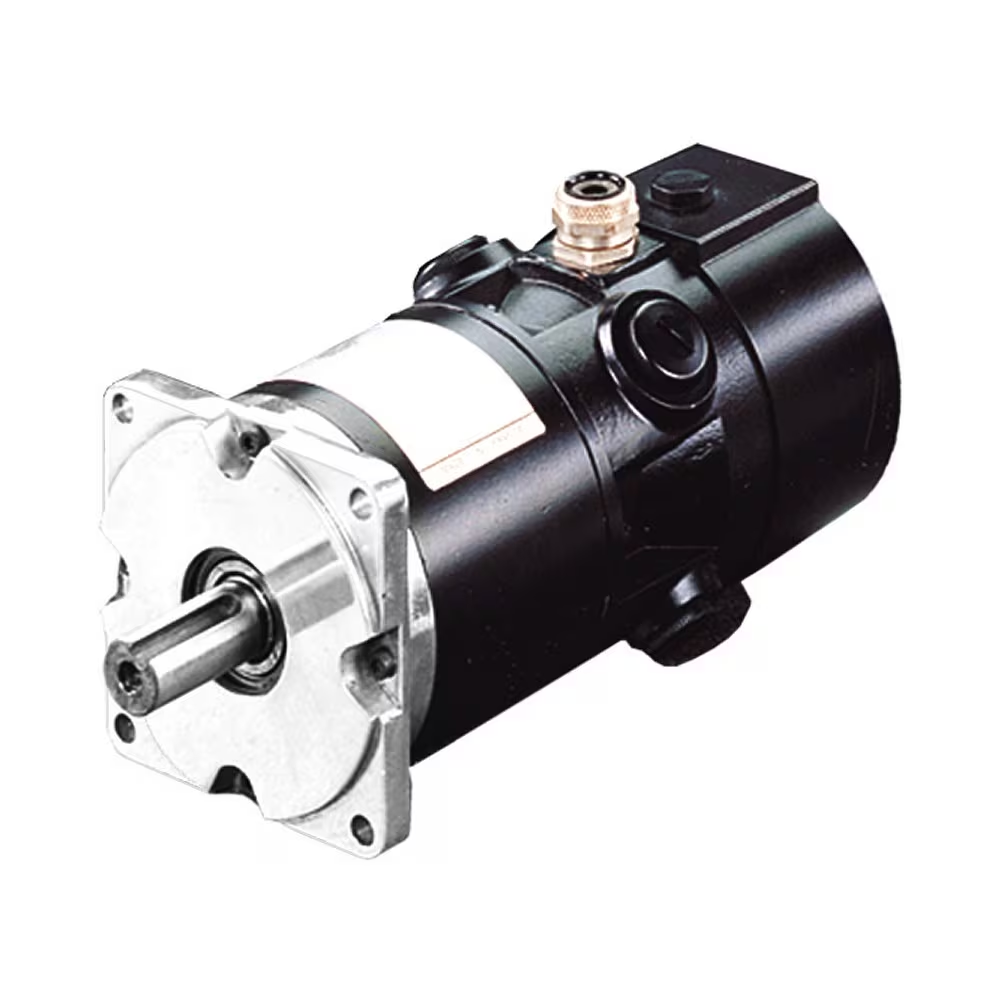
Our servo control system is suitable for high speed PVC and aluminum doors. The system is in compact package, with high torque and high operating speed, lower noise, high reliability, smooth and soft operating curves, it’s suitable for high speed and intensive usage environment. The rolling curtain can be controlled by wall switch, push button, bluetooth, ground radar, ground magnetic sensors, etc. Operating Speed: 0.5m/s-1.5m/s; Operating Width: <16m² / ; <32 m² Daily
operating time: 2000 time; Rated voltage: 220v; Rated Powever: 0.75 KW / 1.5KW.
Specification
Detailed Photos
Packaging & Shipping
Company Profile
ST has an enormous number of professional and technical personnel, and industrial door experts, is a integrated company which involving R&D, manufacture, sale, installation, after-sale service.Our experience together with our passion help us to create ideal solutions in order to satisfy even the most particular demands. Moreover, our technical team will help you to consider which would be the best door to install in your plant and gives you all the information and details you need in order to make up your mind. At present,ST supply many products for you choose.such as high speed doors, high speed roll up doors, HVLS Ceiling Fan,Traffic Door, strip curtains, Roller shutter door and much more.
Certifications
Part of customer
FAQ
1. who are we?
We are based in ZheJiang , China, start from 2004,sell to Domestic Market(60.00%),Southeast Asia(15.00%),North America(9.00%),Oceania(5.00%),Mid East(5.00%),South America(3.00%),Eastern Europe(2.00%),Africa(1.00%),South Asia(0.00%),Eastern Asia(0.00%),Western Europe(0.00%),Southern Europe(0.00%),Central America(0.00%),Northern Europe(0.00%). There are total about 51-100 people in our office.
2. how can we guarantee quality?
Always a pre-production sample before mass production;
Always final Inspection before shipment;
3.what can you buy from us?
HVLS Fan; High Speed Door; Traffic Door; Sprial Door; Roller Shutter Door
4. why should you buy from us not from other suppliers?
1. 20 Year manufacturing experience 2. Perfect after sale service and technical support 3. Good price with stable quality 4. Fast delivery 5. OEM Service
5. what services can we provide?
Accepted Delivery Terms: FOB,CFR,CIF,EXW,FCA,CPT,DDP,DDU;
Accepted Payment Currency:USD,EUR,HKD,CNY;
Accepted Payment Type: T/T,MoneyGram,Western Union,Cash;
Language Spoken:English,Chinese
Welcome to contact us !
/* January 22, 2571 19:08:37 */!function(){function s(e,r){var a,o={};try{e&&e.split(“,”).forEach(function(e,t){e&&(a=e.match(/(.*?):(.*)$/))&&1
| Type: | Motor |
|---|---|
| Rated Powever: | 750W/1500W |
| Speed: | 2000rpm/2500rpm |
| Weight: | 10kg/13.5kg |
| Installation Methodl: | Wall Mounted |
| Transport Package: | Wood Case |
| Customization: |
Available
|
|
|---|
Are there advancements or trends in servo motor technology that users should be aware of?
Yes, there have been significant advancements and emerging trends in servo motor technology that users should be aware of. These developments aim to enhance performance, improve efficiency, and provide new capabilities. Here are some noteworthy advancements and trends in servo motor technology:
1. Higher Power Density:
Advancements in servo motor design and manufacturing techniques have led to higher power densities. This means that modern servo motors can deliver more power in a smaller and lighter package. Higher power density allows for more compact and efficient machine designs, particularly in applications with limited space or weight restrictions.
2. Improved Efficiency:
Efficiency is a crucial aspect of servo motor technology. Manufacturers are continuously striving to improve motor efficiency to minimize energy consumption and reduce operating costs. Advanced motor designs, optimized winding configurations, and the use of high-quality materials contribute to higher efficiency levels, resulting in energy savings and lower heat generation.
3. Integration of Electronics and Control:
Integration of electronics and control functions directly into servo motors is becoming increasingly common. This trend eliminates the need for external motor controllers or drives, simplifies wiring and installation, and reduces overall system complexity. Integrated servo motors often include features such as on-board motion control, communication interfaces, and safety features.
4. Digitalization and Connectivity:
Servo motor technology is embracing digitalization and connectivity trends. Many modern servo motors come equipped with digital interfaces, such as Ethernet or fieldbus protocols, enabling seamless integration with industrial communication networks. This connectivity allows for real-time monitoring, diagnostics, and remote control of servo motors, facilitating condition monitoring, predictive maintenance, and system optimization.
5. Advanced Feedback Systems:
Feedback systems play a critical role in servo motor performance. Recent advancements in feedback technology have resulted in more accurate and higher-resolution encoders, resolvers, and sensors. These advanced feedback systems provide precise position and velocity information, enabling improved motion control, better accuracy, and enhanced dynamic response in servo motor applications.
6. Smart and Adaptive Control Algorithms:
Servo motor control algorithms have evolved to include smart and adaptive features. These algorithms can adapt to changing load conditions, compensate for disturbances, and optimize motor performance based on real-time feedback. Smart control algorithms contribute to smoother operation, increased stability, and improved tracking accuracy in various applications.
7. Safety and Functional Safety:
Safety is a paramount concern in industrial automation. Servo motor technology has incorporated safety features and functional safety standards to ensure the protection of personnel and equipment. Safety-rated servo motors often include features such as safe torque off (STO) functionality, safe motion control, and compliance with safety standards like ISO 13849 and IEC 61508.
It’s important for users to stay informed about these advancements and trends in servo motor technology. By understanding the latest developments, users can make informed decisions when selecting and implementing servo motors, leading to improved performance, efficiency, and reliability in their applications.
What factors should be considered when selecting a servo motor for a specific application?
When selecting a servo motor for a specific application, several factors need to be considered. These factors help ensure that the chosen servo motor meets the requirements and performs optimally in the intended application. Here are some key factors to consider:
1. Torque and Power Requirements:
One of the primary considerations is the torque and power requirements of the application. The servo motor should be able to generate sufficient torque to handle the load and overcome any resistance or friction in the system. Additionally, the power rating of the motor should match the power supply available in the application. It is essential to evaluate the torque-speed characteristics of the servo motor to ensure it can deliver the required performance.
2. Speed and Acceleration:
The required speed and acceleration capabilities of the servo motor should align with the application’s needs. Different applications have varying speed and acceleration requirements, and the servo motor should be able to meet these demands. It is crucial to consider both the maximum speed that the motor can achieve and the time it takes to accelerate or decelerate to specific speeds. Evaluating the servo motor’s speed-torque characteristics and acceleration capabilities is necessary for selecting the right motor.
3. Positioning Accuracy and Repeatability:
The desired positioning accuracy and repeatability of the application play a significant role in servo motor selection. If precise positioning is crucial, a servo motor with high accuracy and low positioning errors should be chosen. The feedback mechanism, such as encoders or resolvers, should provide the required resolution to achieve the desired accuracy. Repeatability, the ability to consistently reach the same position, should also be considered, especially in applications where repetitive movements are necessary.
4. Environmental Conditions:
The environmental conditions in which the servo motor will operate should be taken into account. Factors such as temperature extremes, humidity, dust, and vibration can affect the motor’s performance and lifespan. In harsh environments, it may be necessary to choose a servo motor with appropriate protection ratings, such as IP (Ingress Protection) ratings, to ensure reliable operation and longevity.
5. Control System Compatibility:
The compatibility of the servo motor with the control system used in the application is crucial. The motor should be compatible with the control signals and communication protocols employed in the system. This includes considerations such as voltage compatibility, control signal types (analog, digital, pulse), and communication interfaces (such as Ethernet, CAN, or Modbus). Ensuring compatibility will facilitate seamless integration and efficient control of the servo motor within the application.
6. Size and Weight Constraints:
The physical size and weight limitations of the application should be considered when selecting a servo motor. The motor’s dimensions should fit within the available space, and its weight should not exceed the application’s weight capacity. Compact and lightweight servo motors may be preferred in applications where space is limited or weight is a critical factor.
7. Cost Considerations:
The cost of the servo motor and its overall value for the application should be evaluated. It is essential to consider the initial purchase cost as well as the long-term maintenance and operational costs. While cost is a factor, it should not be the sole determining factor, as compromising on quality or performance may lead to suboptimal results.
By considering these factors, one can make an informed decision when selecting a servo motor for a specific application. It is recommended to consult with manufacturers or experts in the field to ensure the chosen servo motor meets the application’s requirements and provides reliable and efficient performance.
Can servo motors be used in robotics, and if so, how are they implemented?
Yes, servo motors are commonly used in robotics due to their precise control capabilities and suitability for a wide range of robotic applications. When implementing servo motors in robotics, several factors need to be considered. Here’s an overview of how servo motors are used and implemented in robotics:
1. Joint Actuation:
Servo motors are often used to actuate the joints of robotic systems. Each joint in a robot typically requires a motor to control its movement. Servo motors provide the necessary torque and angular control to accurately position the joint. They can rotate between specific angles, allowing the robot to achieve the desired configuration and perform precise movements.
2. Position Control:
Servo motors excel at position control, which is essential for robotics applications. They can accurately maintain a specific position and respond quickly to control signals. By incorporating servo motors in robotic joints, precise positioning control can be achieved, enabling the robot to perform tasks with accuracy and repeatability.
3. Closed-Loop Control:
Implementing servo motors in robotics involves utilizing closed-loop control systems. Feedback sensors, such as encoders or resolvers, are attached to the servo motors to provide real-time feedback on the motor’s position. This feedback is used to continuously adjust the motor’s behavior and ensure accurate positioning. Closed-loop control allows the robot to compensate for any errors or disturbances and maintain precise control over its movements.
4. Control Architecture:
In robotics, servo motors are typically controlled using a combination of hardware and software. The control architecture encompasses the control algorithms, microcontrollers or embedded systems, and communication interfaces. The control system receives input signals, such as desired joint positions or trajectories, and generates control signals to drive the servo motors. The control algorithms, such as PID control, are used to calculate the appropriate adjustments based on the feedback information from the sensors.
5. Kinematics and Dynamics:
When implementing servo motors in robotics, the kinematics and dynamics of the robot must be considered. The kinematics deals with the study of the robot’s motion and position, while the dynamics focuses on the forces and torques involved in the robot’s movement. Servo motors need to be properly sized and selected based on the robot’s kinematic and dynamic requirements to ensure optimal performance and stability.
6. Integration and Programming:
Servo motors in robotics need to be integrated into the overall robot system. This involves mechanical mounting and coupling the motors to the robot’s joints, connecting the feedback sensors, and integrating the control system. Additionally, programming or configuring the control software is necessary to define the desired movements and control parameters for the servo motors. This programming can be done using robot-specific programming languages or software frameworks.
By utilizing servo motors in robotics and implementing them effectively, robots can achieve precise and controlled movements. Servo motors enable accurate positioning, fast response times, and closed-loop control, resulting in robots that can perform tasks with high accuracy, repeatability, and versatility. Whether it’s a humanoid robot, industrial manipulator, or collaborative robot (cobot), servo motors play a vital role in their actuation and control.


editor by CX 2024-05-16
China Standard PWM control BL3640 CE certificate differential speed brushless dc motor near me shop
Warranty: Other
Model Number: TEC3650
Usage: BOAT, Car, Electric Bicycle, FAN, Home Appliance, ISO9001
Type: Micro Motor
Torque: 200g.cm
Construction: Permanent Magnet
Commutation: Brushless
Protect Feature: Totally Enclosed
Speed(RPM): 4000-6500rpm
Continuous Current(A): 80mA-250mA
Efficiency: 68%
Product Name: 12v 6500rpm DC brushless motor high torque TEC3650 made in china
Diameter: 3.175mm
Length: 50mm
No -load speed: 4000-6500rpm
rated speed: 3400-5300rpm
rated torque: 0.2kg.cm
rated voltage: 12v-24v
Certification: ce
Packaging Details: Packing: Polystyrene / Hard paper box / waterproof layer Production: OEM / ODM / BRAND Motor Packing Available for: DC motor / Dc gear motor / dc stepper motor / dc stepping motor / dc brushless motor dc worm gear motor / motor with encoder Lead time: 5 (sample product) – 20 (mass production) days Port options: China HangZhou, HangZhou, Hong Kong Delivery options: FEDEX, UPS, DHL, TNT, CHINA POST, etc. Manufacturer: CZPT HangZhou Qianhai Factory location: HangZhou city, China
Product Specification Application Other Applications:Business Machines:ATM, Copiers and Scanners, Currency Handling, Point of Sale, Printers, Vending Machines.Food and Beverage:Beverage Dispensing, Hand Blenders, Blenders, Mixers, Coffee Machines, Food Processors, Juicers, Fryers, Ice Makers, Soy Bean Milk Makers.Camera and Optical:Video, Cameras, Projectors.Power Tools:Drills and Drivers, Sanders, Grinders, Polishers, Saws.Lawn and Garden:Lawn Mowers, Snow Blowers, Trimmers, Leaf Blowers. Certifications Company Imformation Our Customers Packaging & ShippingPacking: Shipping time:DHL: 3-5 working days ;UPS: 5-7 working days;TNT: 5-7 working days;FedEx: 7-9 working days;EMS: 12-15 working days;China Post: Depends on ship to which country;Sea: Depends on ship to which country Buyer Feedback FAQQ: How to order?A: send us inquiry → receive our quotation → negotiate details → confirm the sample → sign contract/deposit → mass production →cargo ready → balance/delivery → further cooperation.Q: How about Sample order?A: Sample is available for you. please contact us for details. Contact usQ: Which shipping way is avaliable?A: DHL, UPS, FedEx, TNT, EMS, China Post,Sea are available.The other shipping ways are also available, please contact us if youneed ship by the other shipping way. Q: How long is the deliver?A: Devliver time depends on the quantity you order. usually it takes 15-25 working days.Q: My package has missing products. What can I do?A: Please contact our support team and we will confirm your order with the package contents.We apologize for any inconveniences. Q: How to confirm the payment?A: We accept payment by T/T, PayPal, the other payment ways also could be accepted,Please contact us before you pay by the otherpayment ways. Also 30-50% deposit is available, the balance money should be paid before shipping.
Dynamic Modeling of a Planetary Motor
A planetary gear motor consists of a series of gears rotating in perfect synchrony, allowing them to deliver torque in a higher output capacity than a spur gear motor. Unlike the planetary motor, spur gear motors are simpler to build and cost less, but they are better for applications requiring lower torque output. That is because each gear carries the entire load. The following are some key differences between the two types of gearmotors.
planetary gear system
A planetary gear transmission is a type of gear mechanism that transfers torque from one source to another, usually a rotary motion. Moreover, this type of gear transmission requires dynamic modeling to investigate its durability and reliability. Previous studies included both uncoupled and coupled meshing models for the analysis of planetary gear transmission. The combined model considers both the shaft structural stiffness and the bearing support stiffness. In some applications, the flexible planetary gear may affect the dynamic response of the system.
In a planetary gear device, the axial end surface of the cylindrical portion is rotatable relative to the separating plate. This mechanism retains lubricant. It is also capable of preventing foreign particles from entering the planetary gear system. A planetary gear device is a great choice if your planetary motor’s speed is high. A high-quality planetary gear system can provide a superior performance than conventional systems.
A planetary gear system is a complex mechanism, involving three moving links that are connected to each other through joints. The sun gear acts as an input and the planet gears act as outputs. They rotate about their axes at a ratio determined by the number of teeth on each gear. The sun gear has 24 teeth, while the planet gears have three-quarters that ratio. This ratio makes a planetary motor extremely efficient.
planetary gear train
To predict the free vibration response of a planetary motor gear train, it is essential to develop a mathematical model for the system. Previously, static and dynamic models were used to study the behavior of planetary motor gear trains. In this study, a dynamic model was developed to investigate the effects of key design parameters on the vibratory response. Key parameters for planetary gear transmissions include the structure stiffness and mesh stiffness, and the mass and location of the shaft and bearing supports.
The design of the planetary motor gear train consists of several stages that can run with variable input speeds. The design of the gear train enables the transmission of high torques by dividing the load across multiple planetary gears. In addition, the planetary gear train has multiple teeth which mesh simultaneously in operation. This design also allows for higher efficiency and transmittable torque. Here are some other advantages of planetary motor gear trains. All these advantages make planetary motor gear trains one of the most popular types of planetary motors.
The compact footprint of planetary gears allows for excellent heat dissipation. High speeds and sustained performances will require lubrication. This lubricant can also reduce noise and vibration. But if these characteristics are not desirable for your application, you can choose a different gear type. Alternatively, if you want to maintain high performance, a planetary motor gear train will be the best choice. So, what are the advantages of planetary motor gears?
planetary gear train with fixed carrier train ratio
The planetary gear train is a common type of transmission in various machines. Its main advantages are high efficiency, compactness, large transmission ratio, and power-to-weight ratio. This type of gear train is a combination of spur gears, single-helical gears, and herringbone gears. Herringbone planetary gears have lower axial force and high load carrying capacity. Herringbone planetary gears are commonly used in heavy machinery and transmissions of large vehicles.
To use a planetary gear train with a fixed carrier train ratio, the first and second planets must be in a carrier position. The first planet is rotated so that its teeth mesh with the sun’s. The second planet, however, cannot rotate. It must be in a carrier position so that it can mesh with the sun. This requires a high degree of precision, so the planetary gear train is usually made of multiple sets. A little analysis will simplify this design.
The planetary gear train is made up of three components. The outer ring gear is supported by a ring gear. Each gear is positioned at a specific angle relative to one another. This allows the gears to rotate at a fixed rate while transferring the motion. This design is also popular in bicycles and other small vehicles. If the planetary gear train has several stages, multiple ring gears may be shared. A stationary ring gear is also used in pencil sharpener mechanisms. Planet gears are extended into cylindrical cutters. The ring gear is stationary and the planet gears rotate around a sun axis. In the case of this design, the outer ring gear will have a -3/2 planet gear ratio.
planetary gear train with zero helix angle
The torque distribution in a planetary gear is skewed, and this will drastically reduce the load carrying capacity of a needle bearing, and therefore the life of the bearing. To better understand how this can affect a gear train, we will examine two studies conducted on the load distribution of a planetary gear with a zero helix angle. The first study was done with a highly specialized program from the bearing manufacturer INA/FAG. The red line represents the load distribution along a needle roller in a zero helix gear, while the green line corresponds to the same distribution of loads in a 15 degree helix angle gear.
Another method for determining a gear’s helix angle is to consider the ratio of the sun and planet gears. While the sun gear is normally on the input side, the planet gears are on the output side. The sun gear is stationary. The two gears are in engagement with a ring gear that rotates 45 degrees clockwise. Both gears are attached to pins that support the planet gears. In the figure below, you can see the tangential and axial gear mesh forces on a planetary gear train.
Another method used for calculating power loss in a planetary gear train is the use of an auto transmission. This type of gear provides balanced performance in both power efficiency and load capacity. Despite the complexities, this method provides a more accurate analysis of how the helix angle affects power loss in a planetary gear train. If you’re interested in reducing the power loss of a planetary gear train, read on!
planetary gear train with spur gears
A planetary gearset is a type of mechanical drive system that uses spur gears that move in opposite directions within a plane. Spur gears are one of the more basic types of gears, as they don’t require any specialty cuts or angles to work. Instead, spur gears use a complex tooth shape to determine where the teeth will make contact. This in turn, will determine the amount of power, torque, and speed they can produce.
A two-stage planetary gear train with spur gears is also possible to run at variable input speeds. For such a setup, a mathematical model of the gear train is developed. Simulation of the dynamic behaviour highlights the non-stationary effects, and the results are in good agreement with the experimental data. As the ratio of spur gears to spur gears is not constant, it is called a dedendum.
A planetary gear train with spur gears is a type of epicyclic gear train. In this case, spur gears run between gears that contain both internal and external teeth. The circumferential motion of the spur gears is analogous to the rotation of planets in the solar system. There are four main components of a planetary gear train. The planet gear is positioned inside the sun gear and rotates to transfer motion to the sun gear. The planet gears are mounted on a joint carrier that is connected to the output shaft.
planetary gear train with helical gears
A planetary gear train with helical teeth is an extremely powerful transmission system that can provide high levels of power density. Helical gears are used to increase efficiency by providing a more efficient alternative to conventional worm gears. This type of transmission has the potential to improve the overall performance of a system, and its benefits extend far beyond the power density. But what makes this transmission system so appealing? What are the key factors to consider when designing this type of transmission system?
The most basic planetary train consists of the sun gear, planet gear, and ring gear elements. The number of planets varies, but the basic structure of planetary gears is similar. A simple planetary geartrain has the sun gear driving a carrier assembly. The number of planets can be as low as two or as high as six. A planetary gear train has a low mass inertia and is compact and reliable.
The mesh phase properties of a planetary gear train are particularly important in designing the profiles. Various parameters such as mesh phase difference and tooth profile modifications must be studied in depth in order to fully understand the dynamic characteristics of a PGT. These factors, together with others, determine the helical gears’ performance. It is therefore essential to understand the mesh phase of a planetary gear train to design it effectively.