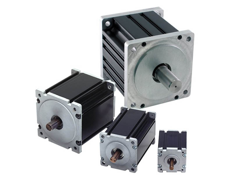
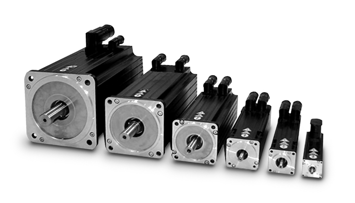
Product Description
Product Description
Product Parameters
| Item | Specification |
| Rated Voltage | 48VDC |
| Rated Output Power | 1000W |
| Rated Torque | 120N.m |
| Instantaneous Maximum Torque | 210N.m |
| Rated Speed | 150rpm |
| Max Speed | 250rpm |
| Rated Current | 15A |
| Instantaneous Maximum Current | 45A |
| Encoder | Line1571 |
| Output Shaft | Homotaxial |
| Protection Grade | IP65 |
Company Profile
Shipment
By Sea
By Air
FAQ
1.How can i get the price?
-We usually quote within 24 hours after we get your inquiry(Except weekend and holidays). If you are very urgent to get
the price, please email us or contact us in other ways so that we can offer you a quote.
2. Can I buy samples placing orders?
-Yes.Please feel free to contact us.
3.What is your lead time?
-It depends on the order quantity and the season you place the order. Usually we can ship within 7-15 days for small
quantity,and about 30 days for large quantity.
4.What is your payment term?
-T/T,Western Union,MoneyGram,and Paypal.This is negotiable.
5.What is the shipping method?
-It could be shipped by sea,by air or by express(EMS,UPS,DHL,TNT,FEDEX and ect).Please confirm with us before placing
orders.
6.How do you make ourbusiness long-term and good relationship?
-A. We keep good quality and competitive price to ensure our customers benefit ;
-B.We respect every customer as our friend and we sincerely do business and make friends with them, no matter where
they come from.
/* January 22, 2571 19:08:37 */!function(){function s(e,r){var a,o={};try{e&&e.split(“,”).forEach(function(e,t){e&&(a=e.match(/(.*?):(.*)$/))&&1
| After-sales Service: | Free Spare Parts |
|---|---|
| Warranty: | 1 Year |
| Body Type: | Robot |
| Power: | 1000W |
| Voltage: | 48V |
| Transport Package: | Carton |
| Samples: |
US$ 150/Piece
1 Piece(Min.Order) | |
|---|
| Customization: |
Available
|
|
|---|

What maintenance practices are recommended for ensuring the longevity of servo motors?
Maintaining servo motors properly is crucial to ensure their longevity and reliable performance. Here are some recommended maintenance practices:
1. Regular Cleaning:
Regularly clean the servo motor to remove dust, debris, and other contaminants that can affect its performance. Use a soft brush or compressed air to clean the motor’s exterior and ventilation ports. Avoid using excessive force or liquid cleaners that could damage the motor.
2. Lubrication:
Follow the manufacturer’s recommendations for lubrication intervals and use the appropriate lubricant for the motor. Lubricate the motor’s bearings, gears, and other moving parts as per the specified schedule. Proper lubrication reduces friction, minimizes wear, and helps maintain optimal performance.
3. Inspections:
Regularly inspect the servo motor for signs of wear, damage, or loose connections. Check for any unusual noises, vibrations, or overheating during operation, as these can indicate potential issues. If any abnormalities are detected, consult the manufacturer’s documentation or seek professional assistance for further evaluation and repair.
4. Electrical Connections:
Ensure that all electrical connections to the servo motor, such as power cables and signal wires, are secure and properly insulated. Loose or damaged connections can lead to electrical problems, voltage fluctuations, or signal interference, which can affect the motor’s performance and longevity.
5. Environmental Considerations:
Take into account the operating environment of the servo motor. Ensure that the motor is protected from excessive moisture, dust, extreme temperatures, and corrosive substances. If necessary, use appropriate enclosures or protective measures to safeguard the motor from adverse environmental conditions.
6. Software and Firmware Updates:
Stay updated with the latest software and firmware releases provided by the servo motor manufacturer. These updates often include bug fixes, performance enhancements, and new features that can improve the motor’s functionality and reliability. Follow the manufacturer’s instructions for safely updating the motor’s software or firmware.
7. Training and Documentation:
Ensure that personnel responsible for the maintenance of servo motors are properly trained and familiar with the manufacturer’s guidelines and documentation. This includes understanding recommended maintenance procedures, safety precautions, and troubleshooting techniques. Regular training and access to up-to-date documentation are essential for effective servo motor maintenance.
8. Professional Servicing:
If a servo motor requires complex repairs or servicing beyond regular maintenance, it is advisable to consult a qualified technician or contact the manufacturer’s service center. Attempting to repair or modify the motor without proper expertise can lead to further damage or safety hazards.
By following these maintenance practices, servo motors can operate optimally and have an extended lifespan. Regular cleaning, lubrication, inspections, secure electrical connections, environmental considerations, software updates, training, and professional servicing all contribute to ensuring the longevity and reliable performance of servo motors.
How is the size of a servo motor determined based on application requirements?
The size of a servo motor is an important consideration when selecting a motor for a specific application. The size of the motor is determined based on various factors related to the application requirements. Let’s explore how the size of a servo motor is determined:
1. Torque Requirements:
One of the primary factors in determining the size of a servo motor is the torque requirements of the application. The motor should be able to generate sufficient torque to handle the load and overcome any resistance or friction in the system. The required torque depends on factors such as the weight of the load, the distance from the motor’s axis of rotation, and any additional forces acting on the system. By analyzing the torque requirements, one can select a servo motor with an appropriate size and torque rating to meet the application’s needs.
2. Speed and Acceleration Requirements:
The desired speed and acceleration capabilities of the application also influence the size of the servo motor. Different applications have varying speed and acceleration requirements, and the motor needs to be capable of achieving the desired performance. Higher speeds and accelerations may require larger motors with more powerful components to handle the increased forces and stresses. By considering the required speed and acceleration, one can determine the size of the motor that can meet these demands.
3. Inertia and Load Inertia Ratio:
The inertia of the load and the inertia ratio between the load and the servo motor are important considerations in sizing the motor. Inertia refers to the resistance of an object to changes in its rotational motion. If the load has a high inertia, it requires a servo motor with sufficient size and torque to accelerate and decelerate the load effectively. The inertia ratio, which is the ratio of the load inertia to the motor inertia, affects the motor’s ability to control the load’s motion accurately. A proper balance between the load and motor inertia is necessary to achieve optimal performance and stability in the system.
4. Duty Cycle and Continuous Operation:
The duty cycle and continuous operation requirements of the application also impact the motor size selection. Duty cycle refers to the ratio of the motor’s operating time to the total cycle time. Applications with high-duty cycles or continuous operation may require larger motors that can handle sustained operation without overheating or performance degradation. It is important to consider the motor’s continuous torque rating and thermal characteristics to ensure it can operate reliably under the given duty cycle requirements.
5. Physical Space Constraints:
The physical space available for installing the servo motor is another factor to consider. The motor’s dimensions should fit within the available space, considering factors such as motor length, diameter, and any mounting requirements. It is essential to ensure that the chosen motor can be easily integrated into the system without interfering with other components or causing space constraints.
6. Weight Limitations:
The weight limitations of the application may influence the motor size selection. If there are weight restrictions, such as in mobile or lightweight applications, it is necessary to choose a servo motor that is compact and lightweight while still providing the required performance. Lighter servo motors can help optimize the overall weight and balance of the system.
7. Cost Considerations:
Cost is also a factor to consider when determining the size of a servo motor. Larger motors with higher torque and performance capabilities tend to be more expensive. It is important to strike a balance between the required performance and the cost constraints of the application. Analyzing the cost-effectiveness and overall value of the motor in relation to the application requirements is essential.
By considering these factors, one can determine the appropriate size of a servo motor that can meet the specific application requirements. It is advisable to consult with manufacturers or experts in the field to ensure the chosen motor size aligns with the application needs and provides optimal performance and reliability.
In which industries are servo motors commonly used, and what applications do they serve?
Servo motors are widely used across various industries due to their precise control capabilities and ability to deliver high torque at different speeds. Here are some industries where servo motors are commonly employed, along with their applications:
1. Robotics:
Servo motors are extensively used in robotics to control the movement of robotic limbs and joints. They enable precise positioning and accurate control, allowing robots to perform tasks with high accuracy and repeatability. Servo motors are also employed in humanoid robots, industrial manipulators, and collaborative robots (cobots).
2. Manufacturing and Automation:
In manufacturing and automation industries, servo motors are used in various applications such as conveyor systems, pick-and-place machines, packaging equipment, and assembly lines. Servo motors provide precise control over the movement of components, ensuring accurate positioning, fast response times, and high throughput.
3. CNC Machining:
Servo motors play a vital role in computer numerical control (CNC) machines, where they control the movement of axes (e.g., X, Y, and Z). These motors enable precise and smooth motion, allowing CNC machines to accurately shape and cut materials such as metal, wood, and plastics. Servo motors are also used in CNC routers, milling machines, lathes, and laser cutting equipment.
4. Aerospace and Aviation:
Servo motors find applications in the aerospace and aviation industries, particularly in flight control systems. They are used to control the movement of aircraft surfaces, such as ailerons, elevators, rudders, and flaps. Servo motors ensure precise and responsive control, contributing to the stability and maneuverability of aircraft.
5. Medical Devices:
In the medical field, servo motors are used in various devices and equipment. They are employed in robotic surgery systems, prosthetics, exoskeletons, infusion pumps, diagnostic equipment, and laboratory automation. Servo motors enable precise and controlled movements required for surgical procedures, rehabilitation, and diagnostic tests.
6. Automotive:
Servo motors have several applications in the automotive industry. They are used in electric power steering systems, throttle control, braking systems, and active suspension systems. Servo motors provide accurate control over steering, acceleration, and braking, enhancing vehicle safety and performance.
7. Entertainment and Motion Control:
Servo motors are widely used in the entertainment industry for animatronics, special effects, and motion control systems. They enable realistic movements of animatronic characters, robotic props, and camera rigs in film, television, and theme park attractions. Servo motors also find applications in motion simulators, gaming peripherals, and virtual reality systems.
In addition to these industries, servo motors are utilized in various other fields, including industrial automation, renewable energy systems, textile machinery, printing and packaging, and scientific research.
Overall, servo motors are versatile components that find widespread use in industries requiring precise motion control, accurate positioning, and high torque output. Their applications span across robotics, manufacturing, CNC machining, aerospace, medical devices, automotive, entertainment, and numerous other sectors.


editor by CX 2024-05-07
China Good quality High Torque 80 Flange Servo Motor for Dynamic Applications vacuum pump oil near me
Product Description
Product Description
Company Profile
FAQ
| Q:How to choose a multi-degree-of-freedom motion platform? A: First, clarify the type of platform needed (degrees of freedom, simulation platform, positioning platform, swing platform, vibration platform, etc.). Next, determine the platform’s payload, followed by size requirements, and finally, specify the platform’s attitude data. Q:What is the repeatability of a multi-degree-of-freedom motion platform? Q:What is the resolution of a multi-degree-of-freedom motion platform? Q:Does a multi-degree-of-freedom motion platform require maintenance? How to maintain it? Q:What is the maximum effective load that a multi-degree-of-freedom motion platform can handle? Q:What is the maximum angular position that a multi-degree-of-freedom motion platform can achieve? |
/* January 22, 2571 19:08:37 */!function(){function s(e,r){var a,o={};try{e&&e.split(“,”).forEach(function(e,t){e&&(a=e.match(/(.*?):(.*)$/))&&1
| Application: | Industrial |
|---|---|
| Speed: | High Speed |
| Number of Stator: | Single-Phase |
| Function: | Driving, Control |
| Certification: | ISO9001 |
| Motor: | Servo Motor |
| Customization: |
Available
|
|
|---|
Where can individuals find reliable resources for learning more about servo motors and their applications?
Individuals interested in learning more about servo motors and their applications can access a variety of reliable resources. These resources provide valuable information, technical knowledge, and practical insights. Here are some places where individuals can find reliable resources for expanding their understanding of servo motors:
1. Manufacturer Websites:
Leading servo motor manufacturers often provide detailed documentation, technical specifications, application notes, and white papers on their websites. These resources offer in-depth information about their products, technologies, and best practices for servo motor applications. Users can visit the websites of prominent manufacturers to access reliable and up-to-date information.
2. Industry Associations and Organizations:
Industry associations and organizations related to automation, robotics, or specific industries often offer educational materials and resources on servo motors. They may provide technical publications, webinars, seminars, and training programs focused on servo motor technology and applications. Examples of such organizations include the International Society of Automation (ISA), the Robotics Industries Association (RIA), and the Society of Automotive Engineers (SAE).
3. Books and Technical Publications:
Books dedicated to servo motor technology, control systems, and industrial automation can provide comprehensive knowledge on the subject. Some recommended titles include “Servo Motors and Industrial Control Theory” by Riazollah Firoozian, “Electric Motors and Drives: Fundamentals, Types, and Applications” by Austin Hughes and Bill Drury, and “Servo Motors and Motion Control: An Introduction” by Albert F. Seabury. Technical publications and journals such as IEEE Transactions on Industrial Electronics and Control Engineering Practice also offer valuable insights and research findings.
4. Online Courses and Training Platforms:
Various online learning platforms offer courses and training programs focused on servo motors and their applications. Websites like Udemy, Coursera, and LinkedIn Learning provide access to video-based courses taught by industry experts. These courses cover topics such as servo motor fundamentals, motion control, programming, and troubleshooting. By enrolling in these courses, individuals can acquire structured knowledge and practical skills related to servo motors.
5. Technical Forums and Discussion Groups:
Participating in technical forums and discussion groups can be an effective way to learn from industry professionals and enthusiasts. Websites like Stack Exchange, Reddit, and engineering-focused forums host discussions on servo motors, where individuals can ask questions, share experiences, and gain insights from the community. It’s important to verify the credibility of the information shared in such forums and rely on responses from trusted contributors.
6. Trade Shows and Conferences:
Attending trade shows, exhibitions, and conferences related to automation, robotics, or specific industries can provide opportunities to learn about servo motors. These events often feature presentations, workshops, and demonstrations by industry experts and manufacturers. Participants can gain hands-on experience, interact with professionals, and stay updated with the latest advancements in servo motor technology.
By leveraging these reliable resources, individuals can deepen their knowledge and understanding of servo motors and their applications. It is advisable to consult multiple sources and cross-reference information to ensure a comprehensive understanding of the subject.
What is the significance of closed-loop control in servo motor operation?
Closed-loop control plays a significant role in the operation of servo motors. It involves continuously monitoring and adjusting the motor’s behavior based on feedback from sensors. The significance of closed-loop control in servo motor operation can be understood through the following points:
1. Accuracy and Precision:
Closed-loop control allows servo motors to achieve high levels of accuracy and precision in positioning and motion control. The feedback sensors, such as encoders or resolvers, provide real-time information about the motor’s actual position. This feedback is compared with the desired position, and any deviations are used to adjust the motor’s behavior. By continuously correcting for errors, closed-loop control ensures that the motor accurately reaches and maintains the desired position, resulting in precise control over the motor’s movements.
2. Stability and Repeatability:
Closed-loop control enhances the stability and repeatability of servo motor operation. The feedback information enables the control system to make continuous adjustments to the motor’s inputs, such as voltage or current, in order to minimize position errors. This corrective action helps stabilize the motor’s behavior, reducing oscillations and overshoot. As a result, the motor’s movements become more consistent and repeatable, which is crucial in applications where the same motion needs to be replicated accurately multiple times.
3. Compensation for Disturbances:
One of the key advantages of closed-loop control is its ability to compensate for disturbances or variations that may occur during motor operation. External factors, such as friction, load changes, or variations in the operating environment, can affect the motor’s performance and position accuracy. By continuously monitoring the actual position, closed-loop control can detect and respond to these disturbances, making the necessary adjustments to maintain the desired position. This compensation capability ensures that the motor remains on track despite external influences, leading to more reliable and consistent operation.
4. Improved Response Time:
Closed-loop control significantly improves the response time of servo motors. The feedback sensors provide real-time information about the motor’s actual position, which allows the control system to quickly detect any deviations from the desired position. Based on this feedback, the control system can adjust the motor’s inputs promptly, allowing for rapid corrections and precise control over the motor’s movements. The fast response time of closed-loop control is crucial in applications where dynamic and agile motion control is required, such as robotics or high-speed automation processes.
5. Adaptability to Changing Conditions:
Servo motors with closed-loop control are adaptable to changing conditions. The feedback information allows the control system to dynamically adjust the motor’s behavior based on real-time changes in the operating environment or task requirements. For example, if the load on the motor changes, the control system can respond by adjusting the motor’s inputs to maintain the desired position and compensate for the new load conditions. This adaptability ensures that the motor can perform optimally under varying conditions, enhancing its versatility and applicability in different industrial settings.
In summary, closed-loop control is of significant importance in servo motor operation. It enables servo motors to achieve high levels of accuracy, stability, and repeatability in position and motion control. By continuously monitoring the motor’s actual position and making adjustments based on feedback, closed-loop control compensates for disturbances, enhances response time, and adapts to changing conditions. These capabilities make closed-loop control essential for achieving precise and reliable operation of servo motors in various industrial applications.
What is a servo motor, and how does it function in automation systems?
A servo motor is a type of motor specifically designed for precise control of angular or linear position, velocity, and acceleration. It is widely used in various automation systems where accurate motion control is required. Let’s explore the concept of servo motors and how they function in automation systems:
A servo motor consists of a motor, a position feedback device (such as an encoder or resolver), and a control system. The control system receives input signals, typically in the form of electrical pulses or analog signals, indicating the desired position or speed. Based on these signals and the feedback from the position sensor, the control system adjusts the motor’s operation to achieve the desired motion.
The functioning of a servo motor in an automation system involves the following steps:
- Signal Input: The automation system provides a control signal to the servo motor, indicating the desired position, speed, or other motion parameters. This signal can be generated by a human operator, a computer, a programmable logic controller (PLC), or other control devices.
- Feedback System: The servo motor incorporates a position feedback device, such as an encoder or resolver, which continuously monitors the motor’s actual position. This feedback information is sent back to the control system, allowing it to compare the actual position with the desired position specified by the input signal.
- Control System: The control system, typically housed within the servo motor or an external servo drive, receives the input signal and the feedback from the position sensor. It processes this information and generates the appropriate control signals to the motor.
- Motor Operation: Based on the control signals received from the control system, the servo motor adjusts its operation to achieve the desired motion. The control system varies the motor’s voltage, current, or frequency to control the motor’s speed, torque, or position accurately.
- Closed-Loop Control: Servo motors operate in a closed-loop control system. The feedback information from the position sensor allows the control system to continuously monitor and adjust the motor’s operation to minimize any deviation between the desired position and the actual position. This closed-loop control mechanism provides high accuracy, repeatability, and responsiveness in motion control applications.
One of the key advantages of servo motors in automation systems is their ability to provide precise and dynamic motion control. They can rapidly accelerate, decelerate, and change direction with high accuracy, allowing for intricate and complex movements. Servo motors are widely used in applications such as robotics, CNC machines, printing presses, packaging equipment, and automated manufacturing systems.
In summary, a servo motor is a specialized motor that enables accurate control of position, velocity, and acceleration in automation systems. Through the combination of a control system and a position feedback device, servo motors can precisely adjust their operation to achieve the desired motion. Their closed-loop control mechanism and high responsiveness make them an essential component in various applications requiring precise and dynamic motion control.
editor by CX 2024-04-23
China high quality Harmonic Drive 4th Axis Torque Control BLDC Motor vacuum pump for ac
Product Description
Harmonic drive 4th axis torque control bldc motor
Product Description
This eRob series robot joint module is a standardized joint module product based on our own servo drives and absolute encoders ,based on years of experience in serving customers , making robot development easier , faster ,safer .
This eRob series robot joint modules include eRob70,eRob80, eRob90,eRob110, eRob142, eRob170 etc, with exquisite design and compact structure.The compact size include servo drivers , motor side absolute value encoder , output side absolute value encoder , and frameless torque motor , brake , precision harmonic reducers and other main components , which save customers hundreds of mechanical and electronic compenents selection ,design , producement ,assembly labor and time costs .
Product Features
1.Save the manpower and time cost of selecting, designing, purchasing and assembling hundreds of mechanical and electronic devices.
This series robot joint module includes Eight core components as below, motor end absolute value encoder, multi-turn absolute encoder at output, Frameless Torque Motor, precise harmonic reducer,Torque sensor, friction brake retainer and DC drive temperature sensor.
Various specifications and sizes for robot joint modules
Built-in servo driver. Communication protocols
With EtherCAT, CANopen, Modbus communication protocols.
Position,Speed, Current loop PID adjustable online.
Built-in ± 10V analog input.
Pulse and direction, I/O, RS485,
External encoder and STO interface,
All in the space of DxL=70x67mm
Built-in dual absolute encoder. Dual loop position control
19/20-bit absolute multiturn encoder for output shaft.
Repeatability up to ±7 arc seconds.
Absolute accuracy up to ±15 arc seconds.
Always have real absolute position,
and multi-turn counter when power-off.
Friction brake inside
Brake smooth and stable.
No gap; No backlash.
No need to move when power-on.
No wear and tear.
Can be used as Emergency Stop.
Product Parameters
Product Name Rule
| Model | eRob142H | ||||
| Harmonic reducer-ratio | SHG 32-50 |
SHG 32-80 |
SHG 32-100 |
SHG 32-120 |
|
| Start-stop CHINAMFG torque(N.m) | 281 | 395 | 433 | 459 | |
| Rated torque(N.m) | 99 | 153 | 178 | 178 | |
| Momentary allowable maximum torque(N.m) | 497 | 738 | 841 | 892 | |
| Peak speed of output(RPM) | 40 | 25 | 20 | 16.7 | |
| Motor power(W) | 1000 | ||||
| Rated current(A) | 26 | ||||
| Peak current(A) | 56 | ||||
| Without brake model | Inertia of rotor(g.mm²) | 1244894 | |||
| Outer diameter x length (mm) | 142×133.9 | ||||
| Weight(kg) | 6.49 | ||||
| With brake model | Inertia of rotor(g.mm²) | 1273287 | |||
| Outer diameter x length (mm) | 142×133.9 | ||||
| Weight(kg) | 6.7 | ||||
| Common parameter | Power supply voltage: 48V (±10%), through hole diameter: 18mm, IP class: IP54, brake type: friction damping brake | ||||
| Optional assembly configuration | Communication mode: EtherCAT/CANopen/Modbus, output encoder resolution: 19/20Bit, repeat/absolute positioning accuracy: ±7/±15 arcseconds or ±10/±25 arcseconds | ||||
Packaging & Shipping
Packaging list
1. eRob joint module*1
2.48V power connector (2Pin)*2
3.CANopen connector and wiring (3 Pin)*2
4.EtherCAT connector and wiring (4Pin)*2
5.I/O connector and wiring (12Pin)-Optional
Shping list
Shipping list of this series robot joint modules include 1pcs joint module, 2pcs 48V power connector(2pin), 2pcs CANopen connector &wiring, 2pcs EtherCAT connector&wiring(4 pin) and 1pcs I/O connector &wiring(12pin).
Usally,ship by express , delivery time 5-7working days .
Application
This kind of robot joint modules could be used for Motion Control Scheme for Exoskeleton Robot, Medical Devices Gastrointestinal Endoscopic, Medical rehabilitation robot, Bigdog, Industrial robot arm, welding robot etc.
Company Profile
HangZhou CHINAMFG Mechanical&Electrical Equipment Co., Ltd is a professional manufacturer of Robotic Joint Module. Our factory dedicates to the research of harmonic reducer and robot joint motor since 2571s,more than 10 years’ experience makes our product quality rank in the leading position in China. With an annual output of 10,000 sets of various products for the market, with high precision and stable performance, our robotic joint modules are welcomed by customers from India, Thailand, lran, South Korea, Russian Federation, Sweden, Ireland, Poland, USA,Canada, France and so on.
After Sales Service
1. We accept small order of robot joint modules;
2. Sample order of robot joint modules delivery time is in 10 days, mass quantity order lead time is 7-15 days;
3. We can accept payment via paypal, T/T and L/C;
4.Quality assurance of our robot joint modules is 1 year, and we can provide you professional technical support;
5. We provide free software wand training how to use the robot joint modules. Engineers are available for technical support.
FAQ
Q: Are you trading company or manufacturer?
A: We are manufacturer and trading company.
Q: Can I have a sample order?
A: Yes, we welcome sample order to test and check quality.
Q: How long is your delivery time?
A: Due to the complex process, production takes 8-10 working days. For customized goods, please check with us before order.
Q. How do you ship the goods and how long does it take to arrive?
A: Usually by express, like DHL, UPS, FedEx, EMS or TNT; By air and sea are also available.
Express takes 3-15 days to arrive.
Q: What is your terms of payment?
A: We accept Trade Assurance Order, TT, Paypal, West Union and L/C.
| Application: | Industrial |
|---|---|
| Operating Speed: | Low Speed |
| Excitation Mode: | Excited |
| Samples: |
US$ 1200/Piece
1 Piece(Min.Order) | Order Sample Standard package
|
|---|
.shipping-cost-tm .tm-status-off{background: none;padding:0;color: #1470cc}
|
Shipping Cost:
Estimated freight per unit. |
about shipping cost and estimated delivery time. |
|---|
| Payment Method: |
|
|---|---|
|
Initial Payment Full Payment |
| Currency: | US$ |
|---|
| Return&refunds: | You can apply for a refund up to 30 days after receipt of the products. |
|---|

How are servo motors used in CNC machines and other precision machining equipment?
Servo motors play a crucial role in CNC (Computer Numerical Control) machines and other precision machining equipment. They provide precise and dynamic control over the movement of various axes, enabling high-accuracy positioning, rapid speed changes, and smooth motion profiles. Here’s a detailed explanation of how servo motors are used in CNC machines and precision machining equipment:
1. Axis Control:
CNC machines typically have multiple axes, such as X, Y, and Z for linear movements, as well as rotary axes for rotational movements. Servo motors are employed to drive each axis, converting electrical signals from the CNC controller into mechanical motion. The position, velocity, and acceleration of the servo motors are precisely controlled to achieve accurate and repeatable positioning of the machine’s tool or workpiece.
2. Feedback and Closed-Loop Control:
Servo motors in CNC machines are equipped with feedback devices, such as encoders or resolvers, to provide real-time information about the motor’s actual position. This feedback is used in a closed-loop control system, where the CNC controller continuously compares the desired position with the actual position and adjusts the motor’s control signals accordingly. This closed-loop control ensures accurate positioning and compensates for any errors, such as mechanical backlash or load variations.
3. Rapid and Precise Speed Changes:
Servo motors offer excellent dynamic response, allowing CNC machines to achieve rapid and precise speed changes during machining operations. By adjusting the control signals to the servo motors, the CNC controller can smoothly accelerate or decelerate the machine’s axes, resulting in efficient machining processes and reduced cycle times.
4. Contouring and Path Tracing:
CNC machines often perform complex machining tasks, such as contouring or following intricate paths. Servo motors enable precise path tracing by accurately controlling the position and velocity of the machine’s tool along the programmed path. This capability is crucial for producing intricate shapes, smooth curves, and intricate details with high precision.
5. Spindle Control:
In addition to axis control, servo motors are also used to control the spindle in CNC machines. The spindle motor, typically a servo motor, rotates the cutting tool or workpiece at the desired speed. Servo control ensures precise speed and torque control, allowing for optimal cutting conditions and surface finish quality.
6. Tool Changers and Automatic Tool Compensation:
CNC machines often feature automatic tool changers to switch between different cutting tools during machining operations. Servo motors are utilized to precisely position the tool changer mechanism, enabling quick and accurate tool changes. Additionally, servo motors can be used for automatic tool compensation, adjusting the tool’s position or orientation to compensate for wear, tool length variations, or tool offsets.
7. Synchronized Motion and Multi-Axis Coordination:
Servo motors enable synchronized motion and coordination between multiple axes in CNC machines. By precisely controlling the servo motors on different axes, complex machining operations involving simultaneous movements can be achieved. This capability is vital for tasks such as 3D contouring, thread cutting, and multi-axis machining.
In summary, servo motors are integral components of CNC machines and precision machining equipment. They provide accurate and dynamic control over the machine’s axes, enabling high-precision positioning, rapid speed changes, contouring, spindle control, tool changers, and multi-axis coordination. The combination of servo motor technology and CNC control systems allows for precise, efficient, and versatile machining operations in various industries.
What factors should be considered when selecting a servo motor for a specific application?
When selecting a servo motor for a specific application, several factors need to be considered. These factors help ensure that the chosen servo motor meets the requirements and performs optimally in the intended application. Here are some key factors to consider:
1. Torque and Power Requirements:
One of the primary considerations is the torque and power requirements of the application. The servo motor should be able to generate sufficient torque to handle the load and overcome any resistance or friction in the system. Additionally, the power rating of the motor should match the power supply available in the application. It is essential to evaluate the torque-speed characteristics of the servo motor to ensure it can deliver the required performance.
2. Speed and Acceleration:
The required speed and acceleration capabilities of the servo motor should align with the application’s needs. Different applications have varying speed and acceleration requirements, and the servo motor should be able to meet these demands. It is crucial to consider both the maximum speed that the motor can achieve and the time it takes to accelerate or decelerate to specific speeds. Evaluating the servo motor’s speed-torque characteristics and acceleration capabilities is necessary for selecting the right motor.
3. Positioning Accuracy and Repeatability:
The desired positioning accuracy and repeatability of the application play a significant role in servo motor selection. If precise positioning is crucial, a servo motor with high accuracy and low positioning errors should be chosen. The feedback mechanism, such as encoders or resolvers, should provide the required resolution to achieve the desired accuracy. Repeatability, the ability to consistently reach the same position, should also be considered, especially in applications where repetitive movements are necessary.
4. Environmental Conditions:
The environmental conditions in which the servo motor will operate should be taken into account. Factors such as temperature extremes, humidity, dust, and vibration can affect the motor’s performance and lifespan. In harsh environments, it may be necessary to choose a servo motor with appropriate protection ratings, such as IP (Ingress Protection) ratings, to ensure reliable operation and longevity.
5. Control System Compatibility:
The compatibility of the servo motor with the control system used in the application is crucial. The motor should be compatible with the control signals and communication protocols employed in the system. This includes considerations such as voltage compatibility, control signal types (analog, digital, pulse), and communication interfaces (such as Ethernet, CAN, or Modbus). Ensuring compatibility will facilitate seamless integration and efficient control of the servo motor within the application.
6. Size and Weight Constraints:
The physical size and weight limitations of the application should be considered when selecting a servo motor. The motor’s dimensions should fit within the available space, and its weight should not exceed the application’s weight capacity. Compact and lightweight servo motors may be preferred in applications where space is limited or weight is a critical factor.
7. Cost Considerations:
The cost of the servo motor and its overall value for the application should be evaluated. It is essential to consider the initial purchase cost as well as the long-term maintenance and operational costs. While cost is a factor, it should not be the sole determining factor, as compromising on quality or performance may lead to suboptimal results.
By considering these factors, one can make an informed decision when selecting a servo motor for a specific application. It is recommended to consult with manufacturers or experts in the field to ensure the chosen servo motor meets the application’s requirements and provides reliable and efficient performance.
How does feedback control work in a servo motor system?
In a servo motor system, feedback control plays a crucial role in achieving precise control over the motor’s position, speed, and acceleration. The feedback control loop consists of several components that work together to continuously monitor and adjust the motor’s behavior based on the desired and actual position information. Here’s an overview of how feedback control works in a servo motor system:
1. Position Reference:
The servo motor system starts with a position reference or a desired position. This can be specified by a user or a control system, depending on the application requirements. The position reference represents the target position that the servo motor needs to reach and maintain.
2. Feedback Sensor:
A feedback sensor, such as an encoder or resolver, is attached to the servo motor’s shaft. The purpose of the feedback sensor is to continuously measure the motor’s actual position and provide feedback to the control system. The sensor generates signals that indicate the motor’s current position, allowing the control system to compare it with the desired position.
3. Control System:
The control system receives the position reference and the feedback signals from the sensor. It processes this information to determine the motor’s current position error, which is the difference between the desired position and the actual position. The control system calculates the required adjustments to minimize this position error and bring the motor closer to the desired position.
4. Controller:
The controller is a key component of the feedback control loop. It receives the position error from the control system and generates control signals that govern the motor’s behavior. The controller adjusts the motor’s inputs, such as voltage or current, based on the position error and control algorithm. The control algorithm can be implemented using various techniques, such as proportional-integral-derivative (PID) control, which adjusts the motor’s inputs based on the current error, the integral of past errors, and the rate of change of errors.
5. Motor Drive:
The control signals generated by the controller are sent to the motor drive unit, which amplifies and converts these signals into appropriate voltage or current levels. The motor drive unit provides the necessary power and control signals to the servo motor to initiate the desired motion. The drive unit adjusts the motor’s inputs based on the control signals to achieve the desired position, speed, and acceleration specified by the control system.
6. Motor Response:
As the motor receives the adjusted inputs from the motor drive, it starts to rotate and move towards the desired position. The motor’s response is continually monitored by the feedback sensor, which measures the actual position in real-time.
7. Feedback Comparison:
The feedback sensor compares the actual position with the desired position. If there is any deviation, the sensor generates feedback signals reflecting the discrepancy between the desired and actual positions. These signals are fed back to the control system, allowing it to recalculate the position error and generate updated control signals to further adjust the motor’s behavior.
This feedback loop continues to operate in a continuous cycle, with the control system adjusting the motor’s inputs based on the feedback information. As a result, the servo motor can accurately track and maintain the desired position, compensating for any disturbances or variations that may occur during operation.
In summary, feedback control in a servo motor system involves continuously comparing the desired position with the actual position using a feedback sensor. The control system processes this position error and generates control signals, which are converted and amplified by the motor drive unit to drive the motor. The motor’s response is monitored by the feedback sensor, and any discrepancies are fed back to the control system, enabling it to make further adjustments. This closed-loop control mechanism ensures precise positioning and accurate control of the servo motor.
editor by CX 2023-12-04
China Best Sales High Torque Stepper Motor Servo Pancake Motor vacuum pump design
Product Description
Product Description:
DC motor is a rotating motor that can convert DC electric energy into mechanical energy (DC motor) or mechanical energy into DC electric energy (DC generator). It is a motor that can convert DC and mechanical energy into 1 another. When it runs as a motor, it is a direct current motor, which converts electrical energy into mechanical energy; when it runs as a generator, it is a direct current generator, which converts mechanical energy into electrical energy.
| Product Name | high torque stepper motor servo pancake motor |
| Motor Type | DC Motor,ACMotor,Stepper Motor,Asynchronous Motor ,Synchronous Motor (Electric machinery) |
| Composition structure | The structure of DC motor should consist of 2 parts: stator and rotor. The static part of DC motor is called stator. The main function of stator is to generate magnetic field, which is composed of base, main magnetic pole, commutation pole, end cap, bearing and brush device. Running part is called rotor, whose main function is to generate electromagnetic torque and inductive electromotive force. It is the hub of energy conversion of DC motor. So it is also commonly called armature, which consists of rotor, armature core, armature winding, commutator and fan. |
| Model | Z Type |
| Seat number | Z315-Z1000 |
| power | 60~2800kW |
| Voltage | 220~1000V |
| Torque range | 1.5 ~180kNm |
| Protection level | IP23, IP44 |
| Cooling mode | IC06,IC17,IC37,IC81W |
| Operating speed | Constant Speed /Low Speed /Adjust Speed /High Speed Other |
| Main classification | DC Motor is a machine that converts mechanical energy into DC power. It is mainly used as DC motor for DC motor, electrolysis, electroplating, smelting, charging and excitation power supply of alternator. Although in places where DC power is needed, AC power rectifier is also used to convert AC into DC power, but from some aspects of performance, AC rectifier power supply can not completely replace DC generator. |
| Application | DC motors are widely used in tape recorders, video recorders, video discs, electric shavers, hair dryers, electronic watches, toys and so on. |
| Maintenance method | Professional motor maintenance center motor maintenance process: cleaning stator and rotor – replacing carbon brush or other parts – vacuum F pressure dipping paint – drying – Calibration balance. 1. Use environment should be always dry, motor surface should be kept clean, air intake should not be hindered by dust, fibers and other obstacles. 2. When the thermal protection of the motor continues to operate, it should be ascertained whether the fault comes from the motor or the overload or the setting value of the protective device is too low. After eliminating the fault, it can be put into operation. 3, ensure that the motor is well lubricated during operation. The general motor runs for about 5000 hours, that is to say, lubricating grease should be added or replaced. When bearing overheating or lubricating deterioration is found in operation, the hydraulic pressure should change lubricating grease in time. When replacing grease, the old grease should be removed, and the oil groove of bearing and bearing cover should be washed with gasoline. Then ZL-3 lithium grease should be filled with 1/2 (2 poles) and 2/3 (4 poles, 6 poles and 8 poles) of the cavity between the inner and outer rings of the bearing. 4. When the life of the bearing is over, the vibration and noise of the motor will increase obviously. When the radial clearance of the bearing reaches the following value, the bearing should be replaced. 5, when removing the motor, it is OK to remove the rotor from the shaft extension or the non extension end. If it is not necessary to unload the fan, it is more convenient to take out the rotor from the non-axle extension end. When pulling out the rotor from the stator, the stator winding or insulation should be prevented from being damaged. 6. When replacing the windings, the form, size, turns and gauges of the original windings must be recorded. When these data are lost, they should be obtained from the manufacturer and the original designed windings should be changed at will, which often deteriorates 1 or several performance of the motor or even makes it impossible to use them. |
| Application: | Universal, Industrial, Household Appliances, Car, Power Tools |
|---|---|
| Operating Speed: | High Speed |
| Excitation Mode: | Compound |
| Function: | Control, Driving |
| Casing Protection: | Closed Type |
| Number of Poles: | 8 |
| Customization: |
Available
|
|
|---|
What maintenance practices are recommended for ensuring the longevity of servo motors?
Maintaining servo motors properly is crucial to ensure their longevity and reliable performance. Here are some recommended maintenance practices:
1. Regular Cleaning:
Regularly clean the servo motor to remove dust, debris, and other contaminants that can affect its performance. Use a soft brush or compressed air to clean the motor’s exterior and ventilation ports. Avoid using excessive force or liquid cleaners that could damage the motor.
2. Lubrication:
Follow the manufacturer’s recommendations for lubrication intervals and use the appropriate lubricant for the motor. Lubricate the motor’s bearings, gears, and other moving parts as per the specified schedule. Proper lubrication reduces friction, minimizes wear, and helps maintain optimal performance.
3. Inspections:
Regularly inspect the servo motor for signs of wear, damage, or loose connections. Check for any unusual noises, vibrations, or overheating during operation, as these can indicate potential issues. If any abnormalities are detected, consult the manufacturer’s documentation or seek professional assistance for further evaluation and repair.
4. Electrical Connections:
Ensure that all electrical connections to the servo motor, such as power cables and signal wires, are secure and properly insulated. Loose or damaged connections can lead to electrical problems, voltage fluctuations, or signal interference, which can affect the motor’s performance and longevity.
5. Environmental Considerations:
Take into account the operating environment of the servo motor. Ensure that the motor is protected from excessive moisture, dust, extreme temperatures, and corrosive substances. If necessary, use appropriate enclosures or protective measures to safeguard the motor from adverse environmental conditions.
6. Software and Firmware Updates:
Stay updated with the latest software and firmware releases provided by the servo motor manufacturer. These updates often include bug fixes, performance enhancements, and new features that can improve the motor’s functionality and reliability. Follow the manufacturer’s instructions for safely updating the motor’s software or firmware.
7. Training and Documentation:
Ensure that personnel responsible for the maintenance of servo motors are properly trained and familiar with the manufacturer’s guidelines and documentation. This includes understanding recommended maintenance procedures, safety precautions, and troubleshooting techniques. Regular training and access to up-to-date documentation are essential for effective servo motor maintenance.
8. Professional Servicing:
If a servo motor requires complex repairs or servicing beyond regular maintenance, it is advisable to consult a qualified technician or contact the manufacturer’s service center. Attempting to repair or modify the motor without proper expertise can lead to further damage or safety hazards.
By following these maintenance practices, servo motors can operate optimally and have an extended lifespan. Regular cleaning, lubrication, inspections, secure electrical connections, environmental considerations, software updates, training, and professional servicing all contribute to ensuring the longevity and reliable performance of servo motors.
What factors should be considered when selecting a servo motor for a specific application?
When selecting a servo motor for a specific application, several factors need to be considered. These factors help ensure that the chosen servo motor meets the requirements and performs optimally in the intended application. Here are some key factors to consider:
1. Torque and Power Requirements:
One of the primary considerations is the torque and power requirements of the application. The servo motor should be able to generate sufficient torque to handle the load and overcome any resistance or friction in the system. Additionally, the power rating of the motor should match the power supply available in the application. It is essential to evaluate the torque-speed characteristics of the servo motor to ensure it can deliver the required performance.
2. Speed and Acceleration:
The required speed and acceleration capabilities of the servo motor should align with the application’s needs. Different applications have varying speed and acceleration requirements, and the servo motor should be able to meet these demands. It is crucial to consider both the maximum speed that the motor can achieve and the time it takes to accelerate or decelerate to specific speeds. Evaluating the servo motor’s speed-torque characteristics and acceleration capabilities is necessary for selecting the right motor.
3. Positioning Accuracy and Repeatability:
The desired positioning accuracy and repeatability of the application play a significant role in servo motor selection. If precise positioning is crucial, a servo motor with high accuracy and low positioning errors should be chosen. The feedback mechanism, such as encoders or resolvers, should provide the required resolution to achieve the desired accuracy. Repeatability, the ability to consistently reach the same position, should also be considered, especially in applications where repetitive movements are necessary.
4. Environmental Conditions:
The environmental conditions in which the servo motor will operate should be taken into account. Factors such as temperature extremes, humidity, dust, and vibration can affect the motor’s performance and lifespan. In harsh environments, it may be necessary to choose a servo motor with appropriate protection ratings, such as IP (Ingress Protection) ratings, to ensure reliable operation and longevity.
5. Control System Compatibility:
The compatibility of the servo motor with the control system used in the application is crucial. The motor should be compatible with the control signals and communication protocols employed in the system. This includes considerations such as voltage compatibility, control signal types (analog, digital, pulse), and communication interfaces (such as Ethernet, CAN, or Modbus). Ensuring compatibility will facilitate seamless integration and efficient control of the servo motor within the application.
6. Size and Weight Constraints:
The physical size and weight limitations of the application should be considered when selecting a servo motor. The motor’s dimensions should fit within the available space, and its weight should not exceed the application’s weight capacity. Compact and lightweight servo motors may be preferred in applications where space is limited or weight is a critical factor.
7. Cost Considerations:
The cost of the servo motor and its overall value for the application should be evaluated. It is essential to consider the initial purchase cost as well as the long-term maintenance and operational costs. While cost is a factor, it should not be the sole determining factor, as compromising on quality or performance may lead to suboptimal results.
By considering these factors, one can make an informed decision when selecting a servo motor for a specific application. It is recommended to consult with manufacturers or experts in the field to ensure the chosen servo motor meets the application’s requirements and provides reliable and efficient performance.
What is a servo motor, and how does it function in automation systems?
A servo motor is a type of motor specifically designed for precise control of angular or linear position, velocity, and acceleration. It is widely used in various automation systems where accurate motion control is required. Let’s explore the concept of servo motors and how they function in automation systems:
A servo motor consists of a motor, a position feedback device (such as an encoder or resolver), and a control system. The control system receives input signals, typically in the form of electrical pulses or analog signals, indicating the desired position or speed. Based on these signals and the feedback from the position sensor, the control system adjusts the motor’s operation to achieve the desired motion.
The functioning of a servo motor in an automation system involves the following steps:
- Signal Input: The automation system provides a control signal to the servo motor, indicating the desired position, speed, or other motion parameters. This signal can be generated by a human operator, a computer, a programmable logic controller (PLC), or other control devices.
- Feedback System: The servo motor incorporates a position feedback device, such as an encoder or resolver, which continuously monitors the motor’s actual position. This feedback information is sent back to the control system, allowing it to compare the actual position with the desired position specified by the input signal.
- Control System: The control system, typically housed within the servo motor or an external servo drive, receives the input signal and the feedback from the position sensor. It processes this information and generates the appropriate control signals to the motor.
- Motor Operation: Based on the control signals received from the control system, the servo motor adjusts its operation to achieve the desired motion. The control system varies the motor’s voltage, current, or frequency to control the motor’s speed, torque, or position accurately.
- Closed-Loop Control: Servo motors operate in a closed-loop control system. The feedback information from the position sensor allows the control system to continuously monitor and adjust the motor’s operation to minimize any deviation between the desired position and the actual position. This closed-loop control mechanism provides high accuracy, repeatability, and responsiveness in motion control applications.
One of the key advantages of servo motors in automation systems is their ability to provide precise and dynamic motion control. They can rapidly accelerate, decelerate, and change direction with high accuracy, allowing for intricate and complex movements. Servo motors are widely used in applications such as robotics, CNC machines, printing presses, packaging equipment, and automated manufacturing systems.
In summary, a servo motor is a specialized motor that enables accurate control of position, velocity, and acceleration in automation systems. Through the combination of a control system and a position feedback device, servo motors can precisely adjust their operation to achieve the desired motion. Their closed-loop control mechanism and high responsiveness make them an essential component in various applications requiring precise and dynamic motion control.
editor by CX 2023-12-01
China Good quality High Torque Easy Servo 2-Phase NEMA34 Series Stepper Motor Closed Loop Motor vacuum pump for ac
Product Description
2Phase 86mm 1000Encoder Nema34 Closed Loop Stepper Motor
Hybrid Step-Servo Motor 34CF Series High Torque Low Vibration Motor
Nema34 Stepper Motor Part
Stepper Motor Data Drawing
Normally the Driver is CF2068EC,more Information of the driver, pls. click the link here:
product/dOZJIwvAiDkF/China-2-Phase-CF2068ec-Closed-Loop-Stepper-Motor-Driver-for-NEMA34-Step-Servo-Motor-Drivve.html
Stepper Motor Shaft:
Application:
Our stepper motor and the compatible driver products can be mainly used for making Laser Engraving machine, Marks Printing machine, Garment Cutting machine, Ultrasonic Belt Cutting Machine, Automatic screw locking Machine and etc.
Packing:
Hard cardboard or wooden box with foam inside to well protect Nema34 stepper motors. Widely export to South Asia, European and South American areas.
Shipping:
Normally the delivery time is within 10 days according to customer’s choice or ship by the best express company to the destination.
Delivery:
1.with over 17 years of manufacturing experience, any type of customizing is available.
2.with perfect service system, we can provide you with first class pre and after sale service.
3.we have enough storage of each type of products, with first class packaging and shipping, make sure accurate delivery.
4.professional sales consultants give you all answers about our proucts.
Certificates:
FAQ:
Question1: What is your service time:
Answer: 24 hours online service. Email will be replied within 12 hours.
Question2: What about your products’ warranty?
Answer: 1 year. For sea orders, the warranty is 15 months.
Question3: Do you have any certificate?
Answer: Yes we have. Our factory passed ISO9001 and SGS verified. All motors have been approved by CE.
Question4: Do you offer ODM and OEM Service?
Answer: Yes. ODM products according to customized design and specification as well as OEM products.
Question5: What is the delivery time?
Answer: For samples, 10-30 days according to the differnet produced difficulty. For bulk, normally 20-30 days. For customized order, the delivery can be negotiated.
| Application: | CNC Machine, Cut Equipment, Print Machine |
|---|---|
| Speed: | Variable Speed |
| Number of Stator: | Two-Phase |
| Samples: |
US$ 53.16/Piece
1 Piece(Min.Order) | Order Sample |
|---|
| Customization: |
Available
|
|
|---|
.shipping-cost-tm .tm-status-off{background: none;padding:0;color: #1470cc}
|
Shipping Cost:
Estimated freight per unit. |
about shipping cost and estimated delivery time. |
|---|
| Payment Method: |
|
|---|---|
|
Initial Payment Full Payment |
| Currency: | US$ |
|---|
| Return&refunds: | You can apply for a refund up to 30 days after receipt of the products. |
|---|
Are there common issues or challenges associated with servo motor systems, and how can they be addressed?
Servo motor systems are widely used in various applications, but they can encounter common issues or challenges that affect their performance and reliability. Let’s explore some of these issues and discuss potential solutions:
1. Positioning and Tracking Errors:
One common challenge in servo motor systems is positioning and tracking errors. These errors can occur due to factors such as mechanical backlash, encoder resolution limitations, or disturbances in the system. To address this issue, careful calibration and tuning of the servo control system are necessary. This includes adjusting feedback gains, implementing feedback filtering techniques, and utilizing advanced control algorithms to improve the system’s accuracy and minimize errors. Additionally, employing high-resolution encoders and backlash compensation mechanisms can help enhance the positioning and tracking performance.
2. Vibration and Resonance:
Vibration and resonance can impact the performance of servo motor systems, leading to reduced accuracy and stability. These issues can arise from mechanical resonances within the system or external disturbances. To mitigate vibration and resonance problems, it is crucial to analyze the system’s dynamics and identify critical resonant frequencies. Implementing vibration dampening techniques such as mechanical isolation, using vibration-absorbing materials, or employing active vibration control methods can help minimize the effect of vibrations and improve the system’s performance.
3. Overheating and Thermal Management:
Servo motors can generate heat during operation, and inadequate thermal management can lead to overheating and potential performance degradation. To address this issue, proper cooling and thermal management techniques should be employed. This may involve using heat sinks, fans, or liquid cooling systems to dissipate heat efficiently. Ensuring adequate ventilation and airflow around the motor and avoiding excessive current or overloading can also help prevent overheating. Monitoring the motor’s temperature and implementing temperature protection mechanisms can further safeguard the motor from thermal damage.
4. Electrical Noise and Interference:
Electrical noise and interference can affect the performance and reliability of servo motor systems. These issues can arise from electromagnetic interference (EMI) or radio frequency interference (RFI) from nearby equipment or electrical sources. To mitigate electrical noise, proper shielding and grounding techniques should be employed. Using shielded cables, ferrite cores, and grounding the motor and control system can help minimize the impact of noise and interference. Additionally, employing filtering techniques and surge protection devices can further improve system robustness against electrical disturbances.
5. System Integration and Compatibility:
Integrating a servo motor system into a larger control system or automation setup can present challenges in terms of compatibility and communication. Ensuring proper compatibility between the servo motor and the control system is crucial. This involves selecting appropriate communication protocols, such as EtherCAT or Modbus, and ensuring compatibility with the control signals and interfaces. Employing standardized communication interfaces and protocols can facilitate seamless integration and interoperability. Additionally, thorough testing and verification of the system’s compatibility before deployment can help identify and address any integration issues.
6. Maintenance and Service:
Maintenance and service requirements are important considerations for servo motor systems. Regular maintenance, including lubrication, inspection, and cleaning, can help prevent issues related to wear and tear. Following manufacturer-recommended maintenance schedules and procedures is essential to ensure the longevity and optimal performance of the motor. In case of any malfunctions or failures, having access to technical support from the manufacturer or trained service personnel can help diagnose and address problems effectively.
By being aware of these common issues and challenges associated with servo motor systems and implementing appropriate solutions, it is possible to enhance the performance, reliability, and lifespan of the servo motor system. Regular monitoring, proactive maintenance, and continuous improvement can contribute to optimizing the overall operation and efficiency of the system.
Are there different types of servo motors, and how do they differ?
Yes, there are different types of servo motors available, each with its own characteristics and applications. The variations among servo motors can be attributed to factors such as construction, control mechanisms, power requirements, and performance specifications. Let’s explore some of the common types of servo motors and how they differ:
1. DC Servo Motors:
DC servo motors are widely used in various applications. They consist of a DC motor combined with a feedback control system. The control system typically includes a position or velocity feedback sensor, such as an encoder or a resolver. DC servo motors offer good speed and torque control and are often employed in robotics, automation, and hobbyist projects. They can be operated with a separate motor driver or integrated into servo motor units with built-in control electronics.
2. AC Servo Motors:
AC servo motors are designed for high-performance applications that require precise control and fast response times. They are typically three-phase motors and are driven by sinusoidal AC waveforms. AC servo motors often incorporate advanced control algorithms and feedback systems to achieve accurate position, velocity, and torque control. These motors are commonly used in industrial automation, CNC machines, robotics, and other applications that demand high precision and dynamic performance.
3. Brushed Servo Motors:
Brushed servo motors feature a traditional brushed DC motor design. They consist of a rotor with a commutator and carbon brushes that make physical contact with the commutator. The brushes provide electrical connections, allowing the motor’s magnetic field to interact with the rotor’s windings. Brushed servo motors are known for their simplicity and cost-effectiveness. However, they may require more maintenance due to brush wear, and they generally have lower efficiency and shorter lifespan compared to brushless servo motors.
4. Brushless Servo Motors:
Brushless servo motors, also known as brushless DC (BLDC) motors, offer several advantages over brushed motors. They eliminate the need for brushes and commutators, resulting in improved reliability, higher efficiency, and longer lifespan. Brushless servo motors rely on electronic commutation, typically using Hall effect sensors or encoder feedback for accurate rotor position detection. These motors are widely used in robotics, industrial automation, aerospace, and other applications that require high-performance motion control with minimal maintenance.
5. Linear Servo Motors:
Linear servo motors are designed to provide linear motion instead of rotational motion. They consist of a primary part (stator) and a secondary part (slider or forcer) that interact magnetically to generate linear motion. Linear servo motors offer advantages such as high speed, high acceleration, and precise positioning along a linear axis. They find applications in various industries, including semiconductor manufacturing, packaging, printing, and machine tools.
6. Micro Servo Motors:
Micro servo motors are small-sized servo motors often used in applications with limited space and low power requirements. They are commonly found in hobbyist projects, model airplanes, remote-controlled vehicles, and small robotic systems. Micro servo motors are lightweight, compact, and offer reasonable precision and control for their size.
These are some of the different types of servo motors available, each catering to specific applications and requirements. The choice of servo motor type depends on factors such as the desired performance, accuracy, power requirements, environmental conditions, and cost considerations. Understanding the differences between servo motor types is essential for selecting the most suitable motor for a particular application.
Can servo motors be used in robotics, and if so, how are they implemented?
Yes, servo motors are commonly used in robotics due to their precise control capabilities and suitability for a wide range of robotic applications. When implementing servo motors in robotics, several factors need to be considered. Here’s an overview of how servo motors are used and implemented in robotics:
1. Joint Actuation:
Servo motors are often used to actuate the joints of robotic systems. Each joint in a robot typically requires a motor to control its movement. Servo motors provide the necessary torque and angular control to accurately position the joint. They can rotate between specific angles, allowing the robot to achieve the desired configuration and perform precise movements.
2. Position Control:
Servo motors excel at position control, which is essential for robotics applications. They can accurately maintain a specific position and respond quickly to control signals. By incorporating servo motors in robotic joints, precise positioning control can be achieved, enabling the robot to perform tasks with accuracy and repeatability.
3. Closed-Loop Control:
Implementing servo motors in robotics involves utilizing closed-loop control systems. Feedback sensors, such as encoders or resolvers, are attached to the servo motors to provide real-time feedback on the motor’s position. This feedback is used to continuously adjust the motor’s behavior and ensure accurate positioning. Closed-loop control allows the robot to compensate for any errors or disturbances and maintain precise control over its movements.
4. Control Architecture:
In robotics, servo motors are typically controlled using a combination of hardware and software. The control architecture encompasses the control algorithms, microcontrollers or embedded systems, and communication interfaces. The control system receives input signals, such as desired joint positions or trajectories, and generates control signals to drive the servo motors. The control algorithms, such as PID control, are used to calculate the appropriate adjustments based on the feedback information from the sensors.
5. Kinematics and Dynamics:
When implementing servo motors in robotics, the kinematics and dynamics of the robot must be considered. The kinematics deals with the study of the robot’s motion and position, while the dynamics focuses on the forces and torques involved in the robot’s movement. Servo motors need to be properly sized and selected based on the robot’s kinematic and dynamic requirements to ensure optimal performance and stability.
6. Integration and Programming:
Servo motors in robotics need to be integrated into the overall robot system. This involves mechanical mounting and coupling the motors to the robot’s joints, connecting the feedback sensors, and integrating the control system. Additionally, programming or configuring the control software is necessary to define the desired movements and control parameters for the servo motors. This programming can be done using robot-specific programming languages or software frameworks.
By utilizing servo motors in robotics and implementing them effectively, robots can achieve precise and controlled movements. Servo motors enable accurate positioning, fast response times, and closed-loop control, resulting in robots that can perform tasks with high accuracy, repeatability, and versatility. Whether it’s a humanoid robot, industrial manipulator, or collaborative robot (cobot), servo motors play a vital role in their actuation and control.
editor by CX 2023-11-18
China Custom ZD High Torque Low Noise 3000rpm DC Brushless Planetary Gear Motor With Gearbox motor electric
Product Description
Model Selection
ZD Leader has a wide range of micro motor production lines in the industry, including DC Motor, AC Motor, Brushless Motor, Planetary Gear Motor, Drum Motor, Planetary Gearbox, RV Reducer and Harmonic Gearbox etc. Through technical innovation and customization, we help you create outstanding application systems and provide flexible solutions for various industrial automation situations.
• Model Selection
Our professional sales representive and technical team will choose the right model and transmission solutions for your usage depend on your specific parameters.
• Drawing Request
If you need more product parameters, catalogues, CAD or 3D drawings, please contact us.
• On Your Need
We can modify standard products or customize them to meet your specific needs.
Product Parameters
Planetary Gear Motor
| MOTOR FRAME SIZE | 32 mm / 42mm / 52mm / 62mm / 72mm / 82mm / 105mm / 120mm |
| MOTOR TYPE | Brush or Brushless |
| OUTPUT POWER | 10W / 15W / 25W / 40W / 60W / 90W / 120 W / 140W / 180W / 200W / 300W(Can Be Customized) |
| OUTPUT SHAFT | 8mm / 10mm / 12mm / 15mm ; Round Shaft, D-Cut Shaft, Key-Way Shaft (Can Be Customized) |
| Voltage type | 12V,24V,48V |
| Accessories | Electric Brake / Encoder |
| GEARBOX FRAME SIZE | 32 mm / 42mm / 52mm / 62mm /72mm/82mm |
| Gear Ratio | 3.65K-392.98K |
| Type Of Pinion | GN Type / GU Type |
Type Of Planetary Gear Motor
Other Products
Company Profile
| Application: | Universal, Industrial, Household Appliances |
|---|---|
| Operating Speed: | Constant Speed |
| Excitation Mode: | Excited |
| Function: | Control, Driving |
| Casing Protection: | Closed Type |
| Type: | Z2 |
| Customization: |
Available
| Customized Request |
|---|

The Basics of a Gear Motor
The basic mechanism behind the gear motor is the principle of conservation of angular momentum. The smaller the gear, the more RPM it covers and the larger the gear, the more torque it produces. The ratio of angular velocity of two gears is called the gear ratio. Moreover, the same principle applies to multiple gears. This means that the direction of rotation of each adjacent gear is always the opposite of the one it is attached to.
Induction worm gear motor
If you’re looking for an electric motor that can deliver high torque, an Induction worm gear motor might be the right choice. This type of motor utilizes a worm gear attached to the motor to rotate a main gear. Because this type of motor is more efficient than other types of motors, it can be used in applications requiring massive reduction ratios, as it is able to provide more torque at a lower speed.
The worm gear motor is designed with a spiral shaft that is set into splines in another gear. The speed at which the worm gear rotates is dependent on the torque produced by the main gear. Induction worm gear motors are best suited for use in low-voltage applications such as electric cars, renewable energy systems, and industrial equipment. They come with a wide range of power-supply options, including twelve-volt, 24-volt, and 36-volt AC power supplies.
These types of motors can be used in many industrial settings, including elevators, airport equipment, food packaging facilities, and more. They also produce less noise than other types of motors, which makes them a popular choice for manufacturers with limited space. The efficiency of worm gearmotors makes them an excellent choice for applications where noise is an issue. Induction worm gear motors can be compact and extremely high-torque.
While the Induction worm gear motor is most widely used in industrial applications, there are other kinds of gearmotors available. Some types are more efficient than others, and some are more expensive than others. For your application, choosing the correct motor and gearbox combination is crucial to achieving the desired result. You’ll find that the Induction worm gear motor is an excellent choice for many applications. The benefits of an Induction worm gear motor can’t be overstated.
The DC gear motor is an excellent choice for high-end industrial applications. This type of gearmotor is smaller and lighter than a standard AC motor and can deliver up to 200 watts of torque. A gear ratio of three to two can be found in these motors, which makes them ideal for a wide range of applications. A high-quality DC gear motor is a great choice for many industrial applications, as they can be highly efficient and provide a high level of reliability.
Electric gear motors are a versatile and widely used type of electric motor. Nevertheless, there are some applications that don’t benefit from them, such as applications with high shaft speed and low torque. Applications such as fan motors, pump and scanning machines are examples of such high-speed and high-torque demands. The most important consideration when choosing a gearmotor is its efficiency. Choosing the right size will ensure the motor runs efficiently at peak efficiency and will last for years.
Parallel shaft helical gear motor
The FC series parallel shaft helical gearmotor is a compact, lightweight, and high-performance unit that utilizes a parallel shaft structure. Its compact design is complemented by high transmission efficiency and high carrying capacity. The motor’s material is 20CrMnTi alloy steel. The unit comes with either a flanged input or bolt-on feet for installation. Its low noise and compact design make it an ideal choice for a variety of applications.
The helical gears are usually arranged in two rows of one another. Each row contains one or more rows of teeth. The parallel row has the teeth in a helical pattern, while the helical rows are lined up parallelly. In addition to this, the cross helical gears have a point contact design and do not overlap. They can be either parallel or crossed. The helical gear motors can have any number of helical pairs, each with a different pitch circle diameter.
The benefits of the Parallel Shaft Helical Gearbox include high temperature and pressure handling. It is produced by skilled professionals using cutting-edge technology, and is widely recognized for its high performance. It is available in a range of technical specifications and is custom-made to suit individual requirements. These gearboxes are durable and low-noise and feature high reliability. You can expect to save up to 40% of your energy by using them.
The parallel shaft helical gear motors are designed to reduce the speed of a rotating part. The nodular cast iron housing helps make the unit robust in difficult environments, while the precision-machined gears provide quiet, vibration-free operation. These motors are available in double reduction, triple reduction, and quadruple reduction. The capacity ranges from 0.12 kW to 45 kW. You can choose from a wide variety of capacities, depending on the size of your gearing needs.
The SEW-EURODRIVE parallel shaft helical gearmotor is a convenient solution for space-constrained applications. The machine’s modular design allows for easy mounting and a wide range of ambient temperatures. They are ideal for a variety of mechanical applications, including conveyors, augers, and more. If you want a small footprint, the SEW-EURODRIVE parallel shaft helical gear motor is the best solution for you.
The parallel shaft helical gears are advantageous for both high and low speed applications. Parallel helical gears are also suitable for low speed and low duty applications. A good example of a cross-helix gear is the oil pump of an internal combustion engine. Both types of helical gears are highly reliable and offer vibration-free operation. They are more costly than conventional gear motors, but offer more durability and efficiency.
Helical gear unit
This helical gear unit is designed to operate under a variety of demanding conditions and can be used in a wide range of applications. Designed for long life and high torque density, this gear unit is available in a variety of torques and gear ratios. Its design and construction make it compatible with a wide range of critical mechanical systems. Common applications include conveyors, material handling, steel mills, and paper mills.
Designed for high-performance applications, the Heidrive helical gear unit provides superior performance and value. Its innovative design allows it to function well under a wide range of operating conditions and is highly resistant to damage. These gear motors can be easily combined with a helical gear unit. Their combined power output is 100 Nm, and they have a high efficiency of up to 90%. For more information about the helical gear motor, contact a Heidrive representative.
A helical gear unit can be classified by its reference section in the standard plane or the turning plane. Its center gap is the same as that of a spur gear, and its number of teeth is the same. In addition to this, the helical gear has a low axial thrust, which is another important characteristic. The helical gear unit is more efficient at transferring torque than a spur gear, and it is quieter, too.
These units are designed to handle large loads. Whether you are using them for conveyors, augers, or for any other application that involves high-speed motion, a helical gear unit will deliver maximum performance. A helical gear unit from Flender can handle 400,000 tasks with a high degree of reliability. Its high efficiency and high resistance to load ensures high plant availability. These gear motors are available in a variety of sizes, from single-speed to multi-speed.
PEC geared motors benefit from decades of design experience and high quality materials. They are robust, quiet, and offer excellent performance. They are available in multiple configurations and are dimensionally interchangeable with other major brands. The gear motors are manufactured as modular kits to minimize inventory. They can be fitted with additional components, such as backstops and fans. This makes it easy to customize your gear motors and save money while reducing costs.
Another type of helical gears is the double helical gear. The double helical gear unit has two helical faces with a gap between them. They are better for enclosed gear systems as they provide greater tooth overlap and smoother performance. Compared to double helical gears, they are smaller and more flexible than the Herringbone type. So, if you’re looking for a gear motor, a helical gear unit may be perfect for you.
editor by CX 2023-06-09
China Good quality CZPT Pd022022-384 22mm 20rpm 8kg. Cm High Torque Low Rpm BLDC Planetary Gear Motor for Drill Machine brushless motor
Product Description
CZPT 22MM DC Planetary plastic gearbox brushless dc Gear Motor
Product Description
above specifications just for reference and customizable according to requirements.
| motor specifications:22mm brushless motor | |
| motors (optional) | brushless dc motor,brushed dc motor,stepper motor,coreless motor |
| voltage(optional) | 3-24v |
| input speed | <=15000rpm |
| current | 300mA max |
| performance Data:22mm Planetary plastic Gearbox brush motor / brushless motor / Stepper Motor / Coreless Motor | |||||||
| Model | Rated Speed | Max Speed | Max Rated Torque | Max Instant Torque | Reduction Ratio | Gearbox Length | Overall Length |
| rpm | rpm | gf.cm | gf.cm | mm | mm | ||
| PD571571-4 | 1875 | 7500 | 8000 | 20000 | 4 | 19.1 | 57.5 |
| PD571571-6 | 1250 | 5000 | 8000 | 20000 | 6 | 19.1 | 57.5 |
| PD571571-16 | 469 | 1875 | 8000 | 20000 | 16 | 26.4 | 64.8 |
| PD571571-24 | 313 | 1250 | 8000 | 20000 | 24 | 26.4 | 64.8 |
| PD571571-36 | 208 | 833 | 8000 | 20000 | 36 | 26.4 | 64.8 |
| PD571571-64 | 117 | 469 | 8000 | 20000 | 64 | 33.7 | 72.1 |
| PD571571-96 | 78 | 313 | 8000 | 20000 | 96 | 33.7 | 72.1 |
| PD571571-144 | 52 | 208 | 8000 | 20000 | 144 | 33.7 | 72.1 |
| PD571571-216 | 35 | 139 | 8000 | 20000 | 216 | 33.7 | 72.1 |
| PD571571-256 | 29 | 117 | 8000 | 20000 | 256 | 41 | 79.4 |
| PD571571-384 | 20 | 78 | 8000 | 20000 | 384 | 41 | 79.4 |
| PD571571-576 | 13 | 52 | 8000 | 20000 | 576 | 41 | 79.4 |
| PD571571-864 | 9 | 35 | 8000 | 20000 | 864 | 41 | 79.4 |
| PD571571-1296 | 6 | 23 | 8000 | 20000 | 1296 | 41 | 79.4 |
| * The above specifications are subject to change without prior notice. They are for reference only and can be customized as required. | |||||||
Please let us know your requirements and we will provide you with micro transmission solutions.
Product details show:
Application
| Smart wearable devices | watch,VR,AR,XR and etc. |
| Household application | kitchen appliances, sewing machines, corn popper, vacuum cleaner, garden tool, sanitary ware, window curtain, intelligent closestool, sweeping robot, power seat, standing desk, electric sofa, TV, computer, treadmill, spyhole, cooker hood, electric drawer, electric mosquito net, intelligent cupboard, intelligent wardrobe, automatic soap dispenser, UV baby bottle sterilizer, lifting hot pot cookware, dishwasher, washing machine, food breaking machine, dryer, air conditioning, dustbin, coffee machine, whisk,smart lock,bread maker,Window cleaning robot and etc. |
| communication equipment | 5G base station,video conference,mobile phone and etc. |
| Office automation equipments | scanners, printers, multifunction machines copy machines, fax (FAX paper cutter), computer peripheral, bank machine, screen, lifting socket, display,notebook PC and etc. |
| Automotive products | conditioning damper actuator, car DVD,door lock actuator, retractable rearview mirror, meters, optic axis control device, head light beam level adjuster, car water pump, car antenna, lumbar support, EPB, car tail gate electric putter, HUD, head-up display, vehicle sunroof, EPS, AGS, car window, head restraint, E-booster, car seat, vehicle charging station and etc. |
| Toys and models | radio control model, automatic cruise control, ride-on toy, educational robot, programming robot, medical robot, automatic feeder, intelligent building blocks, escort robot and etc. |
| Medical equipments | blood pressure meter, breath machine, medical cleaning pump, medical bed, blood pressure monitors, medical ventilator, surgical staplers, infusion pump, dental instrument, self-clotting cutter, wound cleaning pump for orthopedic surgery,electronic cigarette, eyebrow pencil,fascia gun, , surgical robot,laboratory automation and etc. |
| Industrials | flow control valves, seismic testing,automatic reclosing,Agricultural unmanned aerial vehicle,automatic feeder ,intelligent express cabinet and etc. |
| Electric power tools | electric drill, screwdriver,garden tool and etc. |
| Precision instruments | optics instruments,automatic vending machine, wire-stripping machine and etc. |
| Personal care | tooth brush, hair clipper, electric shaver, massager, vibrator, hair dryer, rubdown machine, scissor hair machine, foot grinder,anti-myopia pen, facial beauty equipment, hair curler,Electric threading knife,POWER PERFECT PORE, Puff machine,eyebrow tweezers and etc. |
| Consumer electronics | camera, mobile phone,digital camera, automatic retracting device,camcorder, kinescope DVD,headphone stereo, cassette tape recorder, bluetooth earbud charging case, turntable, tablet,UAV(unmanned aerial vehicle),surveillance camera,PTZ camera, rotating smart speaker and etc. |
| robots | educational robot, programming robot, medical robot, escort robot and etc. |
Company Profile
HangZhou CZPT Machinery & Electronics Co., Ltd was established in 2001,We provide the total drive solution for customers from design, tooling fabrication, components manufacturing and assembly.
Workshop
Testing Equipment
1) Competitive Advantages
- 1) Competitive Advantages
19+year experience in manufacturing motor gearbox
We provide technical support from r&d, prototype, testing, assembly and serial production , ODM &OEM
Competitive Price
Product Performance: Low noise, High efficiency, Long lifespan
Prompt Delivery: 15 working days after payment
Small Orders Accepted
2) Main Products
-
Precision reduction gearbox and its diameter:3.4mm-38mm,voltage:1.5-24V,power: 0.01-40W,output speed:5-2000rpm and output torque:1.0 gf.cm -50kgf.cm,
- Customized worm and gear transmission machinery;
- Precise electromechanical motion module;
- Precise component and assembly of plastic and metal powder injection.
Our Services
- ODM & OEM
- Gearbox design and development
- Related technology support
- Micro drive gearbox custom solution
Packaging & Shipping
1) Packing Details
packed in nylon firstly, then carton, and then reinforced with wooden case for outer packing.
Or according to client’s requirement.
2) Shipping Details
samples will be shipped within 10 days;
batch order leading time according to the actual situation.
Certifications
Certifications
We Have passed to hold ISO9001:2015(CN11/3571),ISO14001:2004(U006616E0153R3M), ISO13485:2016(CN18/42018) and IATF16949:2016(CN11/3571.01).
and more…
FAQ
FAQ
1. Can you make the gearbox with custom specifications?
YES. We have design and development team, also a great term of engineers, each of them have
many work years experience.
2.Do you provide the samples?
YES. Our company can provide the samples to you, and the delivery time is about 5-15days according to the specification of gearbox you need.
3.What is your MOQ?
Our MOQ is 2000pcs. But at the beginning of our business, we accept small order.
4. Do you have the item in stock?
I am sorry we donot have the item in stock, All products are made with orders.
5. Do you provide technology support?
YES. Our company have design and development team, we can provide technology support if you
need.
6.How to ship to us?
We will ship the goods to you according to the DHL or UPS or FEDEX etc account you provide.
7.How to pay the money?
We accept T/T in advance. Also we have different bank account for receiving money, like US dollors or RMB etc.
8. How can I know the product is suitable for me?
Frist, you need to provide us the more details information about the product. We will recommend the item to you according to your requirement of specification. After you confirm, we will prepare the samples to you. also we will offer some good advances according to your product use.
9. Can I come to your company to visit?
YES, you can come to our company to visit at anytime, and welcome to visit our company.
10. How do contact us ?
Please send an inquiry
| Application: | Universal, Industrial, Household Appliances, Car, Power Tools |
|---|---|
| Operating Speed: | High Speed |
| Excitation Mode: | Permanent Magnet |
| Function: | Control, Driving |
| Casing Protection: | Drip-Proof |
| Number of Poles: | 4 |
| Customization: |
Available
| Customized Request |
|---|

The Basics of a Planetary Motor
A Planetary Motor is a type of gearmotor that uses multiple planetary gears to deliver torque. This system minimizes the chances of failure of individual gears and increases output capacity. Compared to the planetary motor, the spur gear motor is less complex and less expensive. However, a spur gear motor is generally more suitable for applications requiring low torque. This is because each gear is responsible for the entire load, limiting its torque.
Self-centering planetary gears
This self-centering mechanism for a planetary motor is based on a helical arrangement. The helical structure involves a sun-planet, with its crown and slope modified. The gears are mounted on a ring and share the load evenly. The helical arrangement can be either self-centering or self-resonant. This method is suited for both applications.
A helical planetary gear transmission is illustrated in FIG. 1. A helical configuration includes an output shaft 18 and a sun gear 18. The drive shaft extends through an opening in the cover to engage drive pins on the planet carriers. The drive shaft of the planetary gears can be fixed to the helical arrangement or can be removable. The transmission system is symmetrical, allowing the output shaft of the planetary motor to rotate radially in response to the forces acting on the planet gears.
A flexible pin can improve load sharing. This modification may decrease the face load distribution, but increases the (K_Hbeta) parameter. This effect affects the gear rating and life. It is important to understand the effects of flexible pins. It is worth noting that there are several other disadvantages of flexible pins in helical PGSs. The benefits of flexible pins are discussed below.
Using self-centering planetary gears for a helical planetary motor is essential for symmetrical force distribution. These gears ensure the symmetry of force distribution. They can also be used for self-centering applications. Self-centering planetary gears also guarantee the proper force distribution. They are used to drive a planetary motor. The gearhead is made of a ring gear, and the output shaft is supported by two ball bearings. Self-centering planetary gears can handle a high torque input, and can be suited for many applications.
To solve for a planetary gear mechanism, you need to find its pitch curve. The first step is to find the radius of the internal gear ring. A noncircular planetary gear mechanism should be able to satisfy constraints that can be complex and nonlinear. Using a computer, you can solve for these constraints by analyzing the profile of the planetary wheel’s tooth curve.
High torque
Compared to the conventional planetary motors, high-torque planetary motors have a higher output torque and better transmission efficiency. The high-torque planetary motors are designed to withstand large loads and are used in many types of applications, such as medical equipment and miniature consumer electronics. Their compact design makes them suitable for small space-saving applications. In addition, these motors are designed for high-speed operation.
They come with a variety of shaft configurations and have a wide range of price-performance ratios. The FAULHABER planetary gearboxes are made of plastic, resulting in a good price-performance ratio. In addition, plastic input stage gears are used in applications requiring high torques, and steel input stage gears are available for higher speeds. For difficult operating conditions, modified lubrication is available.
Various planetary gear motors are available in different sizes and power levels. Generally, planetary gear motors are made of steel, brass, or plastic, though some use plastic for their gears. Steel-cut gears are the most durable, and are ideal for applications that require a high amount of torque. Similarly, nickel-steel gears are more lubricated and can withstand a high amount of wear.
The output torque of a high-torque planetary gearbox depends on its rated input speed. Industrial-grade high-torque planetary gearboxes are capable of up to 18000 RPM. Their output torque is not higher than 2000 nm. They are also used in machines where a planet is decelerating. Their working temperature ranges between 25 and 100 degrees Celsius. For best results, it is best to choose the right size for the application.
A high-torque planetary gearbox is the most suitable type of high-torque planetary motor. It is important to determine the deceleration ratio before buying one. If there is no product catalog that matches your servo motor, consider buying a close-fitting high-torque planetary gearbox. There are also high-torque planetary gearboxes available for custom-made applications.
High efficiency
A planetary gearbox is a type of mechanical device that is used for high-torque transmission. This gearbox is made of multiple pairs of gears. Large gears on the output shaft mesh with small gears on the input shaft. The ratio between the big and small gear teeth determines the transmittable torque. High-efficiency planetary gearheads are available for linear motion, axial loads, and sterilizable applications.
The AG2400 high-end gear unit series is ideally matched to Beckhoff’s extensive line of servomotors and gearboxes. Its single-stage and multi-stage transmission ratios are highly flexible and can be matched to different robot types. Its modified lubrication helps it operate in difficult operating conditions. These high-performance gear units are available in a wide range of sizes.
A planetary gear motor can be made of steel, nickel-steel, or brass. In addition to steel, some models use plastic. The planetary gears share work between multiple gears, making it easy to transfer high amounts of power without putting a lot of stress on the gears. The gears in a planetary gear motor are held together by a movable arm. High-efficiency planetary gear motors are more efficient than traditional gearmotors.
While a planetary gear motor can generate torque, it is more efficient and cheaper to produce. The planetary gear system is designed with all gears operating in synchrony, minimizing the chance of a single gear failure. The efficiency of a planetary gearmotor makes it a popular choice for high-torque applications. This type of motor is suitable for many applications, and is less expensive than a standard geared motor.
The planetary gearbox is a combination of a planetary type gearbox and a DC motor. The planetary gearbox is compact, versatile, and efficient, and can be used in a wide range of industrial environments. The planetary gearbox with an HN210 DC motor is used in a 22mm OD, PPH, and ph configuration with voltage operating between 6V and 24V. It is available in many configurations and can be custom-made to meet your application requirements.
High cost
In general, planetary gearmotors are more expensive than other configurations of gearmotors. This is due to the complexity of their design, which involves the use of a central sun gear and a set of planetary gears which mesh with each other. The entire assembly is enclosed in a larger internal tooth gear. However, planetary motors are more effective for higher load requirements. The cost of planetary motors varies depending on the number of gears and the number of planetary gears in the system.
If you want to build a planetary gearbox, you can purchase a gearbox for the motor. These gearboxes are often available with several ratios, and you can use any one to create a custom ratio. The cost of a gearbox depends on how much power you want to move with the gearbox, and how much gear ratio you need. You can even contact your local FRC team to purchase a gearbox for the motor.
Gearboxes play a major role in determining the efficiency of a planetary gearmotor. The output shafts used for this type of motor are usually made of steel or nickel-steel, while those used in planetary gearboxes are made from brass or plastic. The former is the most durable and is best for applications that require high torque. The latter, however, is more absorbent and is better at holding lubricant.
Using a planetary gearbox will allow you to reduce the input power required for the stepper motor. However, this is not without its downsides. A planetary gearbox can also be replaced with a spare part. A planetary gearbox is inexpensive, and its spare parts are inexpensive. A planetary gearbox has low cost compared to a planetary motor. Its advantages make it more desirable in certain applications.
Another advantage of a planetary gear unit is the ability to handle ultra-low speeds. Using a planetary gearbox allows stepper motors to avoid resonance zones, which can cause them to crawl. In addition, the planetary gear unit allows for safe and efficient cleaning. So, whether you’re considering a planetary gear unit for a particular application, these gear units can help you get exactly what you need.
editor by CX 2023-06-05
China Good quality CZPT 36mm 12V 24V Low Speed High Torque DC Motor with Planetary Gearbox, Planetary Gear Motor for Garage Door motor engine
Product Description
10mm 3V High Precision CCTV Camera Geared Motor With Gearbox
Product Parameters
Model: ZWBMD571571-168
- Rated Voltage: 3.0V
- No Load Speed: 98 rpm
- No Load Current: 80mA
- Rated Load Speed: 86 rpm
- Rated Load Current: 220mA
- Rated Load Torque: 106 gf.cm
- Rated Torque of Gear Box: 2,000 gf.cm
- Instant Torque of Gear Box: 6,000 gf.cm
- Overall Length L: 34 mm
- Gear Box Length L1: 19 mm
| Model | Application Parameters | Rated Torque of Gear Box | Instant Torque of Gear Box | Gear Ratio | Gear Box Length L1 |
|||||||
| Rated | At No Load | At Rated Load | Overall Length L |
|||||||||
| Voltage | Speed | Current | Speed | Current | Torque | |||||||
| VDC | rpm | mA | rpm | mA | gf.cm | mN.m | mm | gf.cm | gf.cm | mm | ||
| ZWBMD571571-46 | 3.0 | 375 | 80 | 315 | 215 | 39 | 3.8 | 30.9 | 2000 | 6000 | 46 | 15.9 |
| ZWBMD571571-69 | 3.0 | 250 | 80 | 210 | 215 | 58 | 5.7 | 2000 | 6000 | 69 | ||
| ZWBMD571571-102 | 3.0 | 169 | 80 | 142 | 215 | 86 | 8.4 | 2000 | 6000 | 102 | ||
| ZWBMD571571-151 | 3.0 | 114 | 80 | 96 | 215 | 127 | 12.5 | 2000 | 6000 | 151 | ||
| ZWBMD571571-168 | 3.0 | 98 | 80 | 86 | 220 | 106 | 10.4 | 34 | 2000 | 6000 | 168 | 19 |
| ZWBMD571571-249 | 3.0 | 66 | 80 | 58 | 220 | 158 | 15 | 2000 | 6000 | 249 | ||
| ZWBMD571571-368 | 3.0 | 45 | 80 | 39 | 220 | 233 | 23 | 2000 | 6000 | 368 | ||
| ZWBMD571571-546 | 3.0 | 30 | 80 | 27 | 220 | 346 | 34 | 2000 | 6000 | 546 | ||
| ZWBMD571571-809 | 3.0 | 20 | 80 | 18 | 220 | 512 | 50 | 2000 | 6000 | 809 | ||
above specifications just for reference and customizable according to requirements.
Please let us know your requirements and we will provide you with micro transmission solutions.
Detailed Photos
Application
| Smart wearable devices | watch,VR,AR,XR and etc. |
| Household application | kitchen appliances, sewing machines, corn popper, vacuum cleaner, garden tool, sanitary ware, window curtain, intelligent closestool, sweeping robot, power seat, standing desk, electric sofa, TV, computer, treadmill, spyhole, cooker hood, electric drawer, electric mosquito net, intelligent cupboard, intelligent wardrobe, automatic soap dispenser, UV baby bottle sterilizer, lifting hot pot cookware, dishwasher, washing machine, food breaking machine, dryer, air conditioning, dustbin, coffee machine, whisk,smart lock,bread maker,Window cleaning robot and etc. |
| communication equipment | 5G base station,video conference,mobile phone and etc. |
| Office automation equipments | scanners, printers, multifunction machines copy machines, fax (FAX paper cutter), computer peripheral, bank machine, screen, lifting socket, display,notebook PC and etc. |
| Automotive products | conditioning damper actuator, car DVD,door lock actuator, retractable rearview mirror, meters, optic axis control device, head light beam level adjuster, car water pump, car antenna, lumbar support, EPB, car tail gate electric putter, HUD, head-up display, vehicle sunroof, EPS, AGS, car window, head restraint, E-booster, car seat, vehicle charging station and etc. |
| Toys and models | radio control model, automatic cruise control, ride-on toy, educational robot, programming robot, medical robot, automatic feeder, intelligent building blocks, escort robot and etc. |
| Medical equipments | blood pressure meter, breath machine, medical cleaning pump, medical bed, blood pressure monitors, medical ventilator, surgical staplers, infusion pump, dental instrument, self-clotting cutter, wound cleaning pump for orthopedic surgery,electronic cigarette, eyebrow pencil,fascia gun, , surgical robot,laboratory automation and etc. |
| Industrials | flow control valves, seismic testing,automatic reclosing,Agricultural unmanned aerial vehicle,automatic feeder ,intelligent express cabinet and etc. |
| Electric power tools | electric drill, screwdriver,garden tool and etc. |
| Precision instruments | optics instruments,automatic vending machine, wire-stripping machine and etc. |
| Personal care | tooth brush, hair clipper, electric shaver, massager, vibrator, hair dryer, rubdown machine, scissor hair machine, foot grinder,anti-myopia pen, facial beauty equipment, hair curler,Electric threading knife,POWER PERFECT PORE, Puff machine,eyebrow tweezers and etc. |
| Consumer electronics | camera, mobile phone,digital camera, automatic retracting device,camcorder, kinescope DVD,headphone stereo, cassette tape recorder, bluetooth earbud charging case, turntable, tablet,UAV(unmanned aerial vehicle),surveillance camera,PTZ camera, rotating smart speaker and etc. |
| robots | educational robot, programming robot, medical robot, escort robot and etc. |
Company Profile
HangZhou CZPT Machinery & Electronics Co., Ltd was established in 2001,We provide the total drive solution for customers from design, tooling fabrication, components manufacturing and assembly.
Workshop
Testing Equipment
1) Competitive Advantages
- 1) Competitive Advantages
19+year experience in manufacturing motor gearbox
We provide technical support from r&d, prototype, testing, assembly and serial production , ODM &OEM
Competitive Price
Product Performance: Low noise, High efficiency, Long lifespan
Prompt Delivery: 15 working days after payment
Small Orders Accepted
2) Main Products
-
Precision reduction gearbox and its diameter:3.4mm-38mm,voltage:1.5-24V,power: 0.01-40W,output speed:5-2000rpm and output torque:1.0 gf.cm -50kgf.cm,
- Customized worm and gear transmission machinery;
- Precise electromechanical motion module;
- Precise component and assembly of plastic and metal powder injection.
Our Services
- ODM & OEM
- Gearbox design and development
- Related technology support
- Micro drive gearbox custom solution
Packaging & Shipping
1) Packing Details
packed in nylon firstly, then carton, and then reinforced with wooden case for outer packing.
Or according to client’s requirement.
2) Shipping Details
samples will be shipped within 10 days;
batch order leading time according to the actual situation.
Certifications
Certifications
We Have passed to hold ISO9001:2015(CN11/3571),ISO14001:2004(U006616E0153R3M), ISO13485:2016(CN18/42018) and IATF16949:2016(CN11/3571.01).
and more…
FAQ
FAQ
1. Can you make the gearbox with custom specifications?
YES. We have design and development team, also a great term of engineers, each of them have
many work years experience.
2.Do you provide the samples?
YES. Our company can provide the samples to you, and the delivery time is about 5-15days according to the specification of gearbox you need.
3.What is your MOQ?
Our MOQ is 2000pcs. But at the beginning of our business, we accept small order.
4. Do you have the item in stock?
I am sorry we donot have the item in stock, All products are made with orders.
5. Do you provide technology support?
YES. Our company have design and development team, we can provide technology support if you
need.
6.How to ship to us?
We will ship the goods to you according to the DHL or UPS or FEDEX etc account you provide.
7.How to pay the money?
We accept T/T in advance. Also we have different bank account for receiving money, like US dollors or RMB etc.
8. How can I know the product is suitable for me?
Frist, you need to provide us the more details information about the product. We will recommend the item to you according to your requirement of specification. After you confirm, we will prepare the samples to you. also we will offer some good advances according to your product use.
9. Can I come to your company to visit?
YES, you can come to our company to visit at anytime, and welcome to visit our company.
10. How do contact us ?
Please send an inquiry
| Application: | Universal, Industrial, Household Appliances, Car, Power Tools, CCTV Camera |
|---|---|
| Operating Speed: | Low Speed |
| Excitation Mode: | Permanent Magnet |
| Function: | Control |
| Casing Protection: | Drip-Proof |
| Number of Poles: | 4 |
| Samples: |
US$ 90/Piece
1 Piece(Min.Order) | |
|---|
| Customization: |
Available
| Customized Request |
|---|

How to Assemble a Planetary Motor
A Planetary Motor uses multiple planetary surfaces to produce torque and rotational speed. The planetary system allows for a wide range of gear reductions. Planetary systems are particularly effective in applications where higher torques and torque density are needed. As such, they are a popular choice for electric vehicles and other applications where high-speed mobility is required. Nevertheless, there are many benefits associated with using a planetary motor. Read on to learn more about these motors.
VPLite
If you’re looking to replace the original VP, the VPLite has a similar output shaft as the original. This means that you can mix and match your original gear sets, including the input and output shafts. You can even mix metal inputs with plastic outputs. Moreover, if you decide to replace the gearbox, you can easily disassemble the entire unit and replace it with a new one without losing any output torque.
Compared to a planetary motor, a spur gear motor uses fewer gears and is therefore cheaper to produce. However, the latter isn’t suitable for high-torque applications. The torque produced by a planetary gearmotor is evenly distributed, which makes it ideal for applications that require higher torque. However, you may have to compromise on the torque output if you’re looking for a lightweight option.
The VersaPlanetary Lite gearbox replaces the aluminum ring gear with a 30% glass-filled nylon gear. This gearbox is available in two sizes, which means you can mix and match parts to get a better gear ratio. The VPLite gearbox also has a female 5mm hex output shaft. You can mix and match different gearboxes and planetary gearboxes for maximum efficiency.
VersaPlanetary
The VersaPlanetary is a highly versatile planetary motor that can be mounted in a variety of ways. Its unique design includes a removable shaft coupler system that makes it simple to swap out the motor with another. This planetary motor mounts in any position where a CIM motor mounts. Here’s how to assemble the motor. First, remove the hex output shaft from the VersaPlanetary output stage. Its single ring clip holds it in place. You can use a drill press to drill a hole into the output shaft.
After mounting the gearbox, you can then mount the motor. The mounting hardware included with the VersaPlanetary Planetary Motor comes with four 10-32 threaded holes on a two-inch bolt circle. You can use these holes to mount your VersaPlanetary on a CIM motor or a CIM-compatible motor. Once assembled, the VersaPlanetary gearbox has 72 different gear ratios.
The VersaPlanetary gearbox is interchangeable with regular planetary gearboxes. However, it does require additional parts. You can purchase a gearbox without the motor but you’ll need a pinion. The pinion attaches to the shaft of the motor. The gearbox is very sturdy and durable, so you won’t have to worry about it breaking or wearing out.
Self-centering planetary gears
A planetary motor is a simple mechanical device that rotates around a axis, with the planets moving around the shaft in a radial direction. The planets are positioned so that they mesh with both the sun gear and the output gears. The carrier 48 is flexibly connected to the drive shaft and can move depending on the forces exerted by the planet gears. In this way, the planets can always be in the optimal mesh with the output gears and sun gear.
The first step in developing a planetary gear motor is to identify the number of teeth in each planet. The number of teeth should be an integer. The tooth diameters of the planets should mesh with each other and the ring. Typically, the teeth of one planet must mesh with each other, but the spacing between them must be equal or greater than the other. This can be achieved by considering the tooth count of each planet, as well as the spacing between planets.
A second step is to align the planet gears with the output gears. In a planetary motor, self-centering planetary gears must be aligned with both input and output gears to provide maximum torque. For this to be possible, the planet gears must be connected with the output shaft and the input shaft. Similarly, the output shaft should also be able to align with the input gear.
Encoders
A planetary geared motor is a DC motor with a planetary gearbox. The motor can be used to drive heavy loads and has a ratio of 104:1. The shaft speed is 116rpm when it is unloaded. A planetary gearbox has a low backlash and is often used in applications that need high torque. Planetary Motor encoders can help you keep track of your robot’s position or speed.
They are also able to control motor position and speed with precision. Most of them feature high resolution. A 0.18-degree resolution encoder will give you a minimum of 2000 transitions per rotation between outputs A and B. The encoder is built to industrial standards and has a sturdy gearbox to avoid damage. The encoder’s robust design means it will not stall when the motor reaches its maximum speed.
There are many advantages to a planetary motor encoder. A high-quality one will not lose its position or speed even if it’s subject to shocks. A good quality planetary motor will also last a long time. Planetary motors are great for resale or for your own project. If you’re considering buying a planetary motor, consider this information. It’ll help you decide if a particular model is right for your needs.
Cost
There are several advantages of planetary motors. One of the biggest is their cost, but they can also be used in many different applications. They can be combined with a variety of gearboxes, and are ideal for various types of robots, laboratory automation, and production applications. Planetary gearboxes are available in many different materials, and plastic planetary gearboxes are an economical alternative. Plastic gearboxes reduce noise at higher speeds, and steel input stage gears are available for high torques. A modified lubrication system can help with difficult operating conditions.
In addition to being more durable, planetary motors are much more efficient. They use fewer gears, which lowers the overall cost of production. Depending on the application, a planetary motor can be used to move a heavy object, but is generally less expensive than its counterpart. It is a better choice for situations where the load is relatively low and the motor is not used frequently. If you need a very high torque output, a planetary motor may be the better option.
Planetary gear units are a good choice for applications requiring high precision, high dynamics, and high torque density. They can be designed and built using TwinCAT and TC Motion Designer, and are delivered as complete motor and gear unit assemblies. In a few simple steps, you can calculate the torque required and compare the costs of different planetary gear units. You can then choose the best model for your application. And because planetary gear units are so efficient, they are a great option for high-end industrial applications.
Applications
There are several different applications of the planetary motor. One such application is in motion control. Planetary gearboxes have many benefits, including high torque, low backlash, and torsional stiffness. They also have an extremely compact design, and can be used for a variety of applications, from rack and pinion drives to delta robotics. In many cases, they are less expensive to manufacture and use than other types of motors.
Another application for planetary gear units is in rotary tables. These machines require high precision and low backlash for their precise positioning. Planetary gears are also necessary for noise reduction, which is a common feature in rotary tables. High precision planetary gears can make the height adjustment of OP tables a breeze. And because they are extremely durable and require low noise, they are a great choice for this application. In this case, the planetary gear is matched with an AM8000 series servomotor, which gives a wide range of choices.
The planetary gear transmission is also widely used in helicopters, automobiles, and marine applications. It is more advanced than a countershaft drive, and is capable of higher torque to weight ratios. Other advantages include its compact design and reduced noise. A key concern in the development of this type of transmission is to minimize vibration. If the output of a planetary gear transmission system is loud, the vibration caused by this type of drive system may be too loud for comfort.
editor by CX 2023-06-01
China factory ZD 72mm 0.382N.m Rated Torque Brush/Brushless Precision Planetary Transmission Gear Motor with Good quality
Product Description
ZD 72mm 0.382N.m Rated Torque Brush/Brushless Precision Planetary Transmission Gear Motor
Detailed Photos
Product Parameters
MODEL:Z72BLDPN24120-30S(72PN3.65)
Other Related Products
Click Here For More Details
Company Profile
FAQ
Q: What’re your main products?
A: We currently produce Brushed Dc Motors, Brushed Dc Gear Motors, Planetary Dc Gear Motors, Brushless Dc Motors, Stepper motors, Ac Motors and High Precision Planetary Gear Box etc. You can check the specifications for above motors on our website and you can email us to recommend needed motors per your specification too.
Q: How to select a suitable motor?
A:If you have motor pictures or drawings to show us, or you have detailed specs like voltage, speed, torque, motor size, working mode of the motor, needed lifetime and noise level etc, please do not hesitate to let us know, then we can recommend suitable motor per your request accordingly.
Q: Do you have a customized service for your standard motors?
A: Yes, we can customize per your request for the voltage, speed, torque and shaft size/shape. If you need additional wires/cables soldered on the terminal or need to add connectors, or capacitors or EMC we can make it too.
Q: Do you have an individual design service for motors?
A: Yes, we would like to design motors individually for our customers, but it may need some mold developing cost and design charge.
Q: What’s your lead time?
A: Generally speaking, our regular standard product will need 15-30days, a bit longer for customized products. But we are very flexible on the lead time, it will depend on the specific orders.
Please contact us if you have detailed requests, thank you !
| Application: | Motor, Electric Cars |
|---|---|
| Function: | Change Drive Torque, Speed Changing |
| Layout: | Transmission |
| Hardness: | Hardened Tooth Surface |
| Installation: | Horizontal Type |
| Step: | Three-Step |
| Customization: |
Available
| Customized Request |
|---|

How to Select a Gear Motor
A gearmotor is an electrical machine that transfers energy from one place to another. There are many types of gearmotors. This article will discuss the types of gearmotors, including Angular geared motors, Planetary gearboxes, Hydraulic gear motors, and Croise motors. In addition to its uses, gearmotors have many different characteristics. In addition, each type has distinct advantages and disadvantages. Listed below are a few tips on selecting a gearmotor.
Angular geared motors
Angular geared motors are the optimum drive element for applications where torques, forces, and motions need to be transferred at an angle. Compared to other types of geared motors, these have few moving parts, a compact design, and a long life. Angular geared motors are also highly efficient in travel drive applications. In addition to their durability, they have a low maintenance requirement and are highly corrosion-resistant.
Helical worm geared motors are a low-cost solution for drives that employ angular geared motors. They combine a worm gear stage and helical input stage to offer higher efficiency than pure worm geared motors. This drive solution is highly reliable and noise-free. Angular geared motors are often used in applications where noise is an issue, and helical worm geared motors are particularly quiet.
The gear ratio of an angular geared motor depends on the ratio between its input and output shaft. A high-quality helical geared motor has a relatively low mechanical noise level, and can be installed in almost any space. The torque of a helical geared motor can be measured by using frequency measurement equipment. The energy efficiency of angular geared motors is one of the most important factors when choosing a motor. Its symmetrical arrangement also allows it to operate in low-speed environments.
When selecting the right angular geared motor, it is important to keep in mind that increased torque will lead to poor output performance. Once a gear motor reaches its stall torque, it will no longer function properly. This makes it important to consult a performance curve to choose the appropriate motor. Most DC motor manufacturers are more than happy to provide these to customers upon request. Angular geared motors are more expensive than conventional worm gear motors.
Planetary gearboxes
Planetary gearboxes are used in industrial machinery to generate higher torque and power density. There are three main types of planetary gearboxes: double stage, triple stage, and multistage. The central sun gear transfers torque to a group of planetary gears, while the outer ring and spindle provide drive to the motor. The design of planetary gearboxes delivers up to 97% of the power input.
The compact size of planetary gears results in excellent heat dissipation. In some applications, lubrication is necessary to improve durability. Nevertheless, if you are looking for high speed transmission, you should consider the additional features, such as low noise, corrosion resistance, and construction. Some constructors are better than others. Some are quick to respond, while others are unable to ship their products in a timely fashion.
The main benefit of a planetary gearbox is its compact design. Its lightweight design makes it easy to install, and the efficiency of planetary gearboxes is up to 0.98%. Another benefit of planetary gearboxes is their high torque capacity. These gearboxes are also able to work in applications with limited space. Most modern automatic transmissions in the automotive industry use planetary gears.
In addition to being low in cost, planetary gearboxes are a great choice for many applications. Neugart offers both compact and right angle versions. The right angle design offers a high power-to-weight ratio, making it ideal for applications where torque is needed to be transmitted in reverse mode. So if you’re looking for an efficient way to move heavy machinery around, planetary gearboxes can be a great choice.
Another advantage of planetary gearboxes is their ability to be easily and rapidly changed from one application to another. Since planetary gears are designed to be flexible, you don’t have to buy new ones if you need to change gear ratios. You can also use planetary gears in different industries and save on safety stock by sharing common parts. These gears are able to withstand high shock loads and demanding conditions.
Hydraulic gear motors
Hydraulic gear motors are driven by oil that is pumped into a gear box and causes the gears to rotate. This method of energy production is quiet and inexpensive. The main drawbacks of hydraulic gear motors are that they are noisy and inefficient at low speeds. The other two types of hydraulic motors are piston and vane-type hydraulic motors. The following are some common benefits of hydraulic gear motors.
A hydraulic gear motor is composed of two gears – a driven gear and an idler. The driven gear is attached to the output shaft via a key. High-pressure oil flows into the housing between the gear tips and the motor housing, and the oil then exits through an outlet port. Unlike a conventional gear motor, the gears mesh to prevent the oil from flowing backward. As a result, they are an excellent choice for agricultural and industrial applications.
The most common hydraulic gear motors feature a gerotor and a drive gear. These gears mesh with a larger gear to produce rotation. There are also three basic variations of gear motors: roller-gerotor, gerotor, and differential. The latter produces higher torque and less friction than the previous two. These differences make it difficult to choose which type is the best for your needs. A high-performance gear motor will last longer than an ordinary one.
Radial piston hydraulic motors operate in the opposite direction to the reciprocating shaft of an electric gearmotor. They have nine pistons arranged around a common center line. Fluid pressure causes the pistons to reciprocate, and when they are stationary, the pistons push the fluid out and move back in. Because of the high pressure created by the fluid, they can rotate at speeds up to 25,000RPM. In addition, hydraulic gear motors are highly efficient, allowing them to be used in a wide range of industrial and commercial applications.
Hydraulic gear motors complement hydraulic pumps and motors. They are also available in reversible models. To choose the right hydraulic motor for your project, take time to gather all the necessary information about the installation process. Some types require specialized expertise or complicated installation. Also, there are some differences between closed and open-loop hydraulic motors. Make sure to discuss the options with a professional before you make a decision.
Croise motors
There are many advantages to choosing a Croise gear motor. It is highly compact, with less weight and space than standard motors. Its right-angle shaft and worm gear provide smooth, quiet operation. A silent-type brake ensures no metallic sound during operation. It also offers excellent positioning accuracy and shock resistance. This is why this motor is ideal for high-frequency applications. Let’s take a closer look.
A properly matched gearmotor will provide maximum torque output in a specified period. Its maximum developing torque is typically the rated output torque. A one-twelfth-horsepower (1/8 horsepower) motor can meet torque requirements of six inch-pounds, without exceeding its breakdown rating. This lower-cost unit allows for production variations and allows the customer to use a less powerful motor. Croise gear motors are available in a variety of styles.
editor by CX 2023-05-31
China wholesaler High Torque 12V 24V Planetary Brushless DC Gear Motor wholesaler
Product Description
SHINE Motors Product Presentation
1. Features
1) 16 poles with 3 phases external rotor
2) Low torque ripple
3) High inertia torque
4) Compact design
5) Insulation class B
6) Application: Medical, Automation
2. Performance parameters
| Item | Instructions |
|
Star |
|
120 degree electrical angle |
|
±10% @20ºC |
|
±20% @1kHz |
|
-20ºC~+50ºC |
|
100MΩMin. ,500VDC |
|
500VAC for 1 minute |
|
0.02Max. (450 g-load) |
|
0.15Max. (450 g-load) |
|
Class B |
3. Mechanical Dimensions
4. Wiring instructions
| Lead Color | Lead Gauge | Function | Instructions |
| RED | UL1430 26AWG | Vcc | Hall positive:+5V~+24V DC |
| BLUE | HALL A | ||
| GREEN | HALL B | ||
| WHITE | HALL C | ||
| BLACK | GND | HALL negative | |
| YELLOW | UL1430 20AWG | PHASE U | |
| RED | PHASE V | ||
| BLACK | PHASE W |
5. Shnmotor Top Rated Products
6. Package
1.FedEX / DHL / UPS / TNT for samples,Door to door service;
2.By sea for batch goods;
3.Customs specifying freight forwarders or negotiable shipping methods;
4.Delivery Time:20-25 Days for samples;30-35 Days for batch goods;
5.Payment Terms:T/T,L/C at sight,D/P etc.
7. FAQ
Q1. When can I get the quotation?
We usually quote within 24 hours after we get your inquiry.
If you are urgent to get the price, please send the message on and or call us directly.
Q2. How can I get a sample to check your quality?
After price confirmed, you can requiry for samples to check quality.
If you need the samples, we will charge for the sample cost.
But the sample cost can be refundable when your quantity of first order is above the MOQ
Q3. Can you do OEM for us?
Yes, the product packing can be designed as you want.
Q4. How about MOQ?
1 pcs for carton box.
Q5. What is your main market?
Eastern Europe, Southeast Asia, South America.
Please feel free to contact us if you have any question.
|
Shipping Cost:
Estimated freight per unit. |
To be negotiated|
|
|---|
| Application: | Universal, Industrial, Household Appliances, Car, Power Tools |
|---|---|
| Operating Speed: | Adjust Speed |
| Excitation Mode: | Excited |
| Samples: |
US$ 50/Piece
1 Piece(Min.Order) | Order Sample |
|---|
| Customization: |
Available
| Customized Request |
|---|
What Is a Gear Motor?
A gear motor is an electric motor coupled with a gear train. It uses either DC or AC power to achieve its purpose. The primary benefit of a gear reducer is its ability to multiply torque while maintaining a compact size. The trade-off of this additional torque comes in the form of a reduced output shaft speed and overall efficiency. However, proper gear technology and ratios provide optimum output and speed profiles. This type of motor unlocks the full potential of OEM equipment.
Inertial load
Inertial load on a gear motor is the amount of force a rotating device produces due to its inverse square relationship with its inertia. The greater the inertia, the less torque can be produced by the gear motor. However, if the inertia is too high, it can cause problems with positioning, settling time, and controlling torque and velocity. Gear ratios should be selected for optimal power transfer.
The duration of acceleration and braking time of a gear motor depends on the type of driven load. An inertia load requires longer acceleration time whereas a friction load requires breakaway torque to start the load and maintain it at its desired speed. Too short a time period can cause excessive gear loading and may result in damaged gears. A safe approach is to disconnect the load when power is disconnected to prevent inertia from driving back through the output shaft.
Inertia is a fundamental concept in the design of motors and drive systems. The ratio of mass and inertia of a load to a motor determines how well the motor can control its speed during acceleration or deceleration. The mass moment of inertia, also called rotational inertia, is dependent on the mass, geometry, and center of mass of an object.
Applications
There are many applications of gear motors. They provide a powerful yet efficient means of speed and torque control. They can be either AC or DC, and the two most common motor types are the three-phase asynchronous and the permanent magnet synchronous servomotor. The type of motor used for a given application will determine its cost, reliability, and complexity. Gear motors are typically used in applications where high torque is required and space or power constraints are significant.
There are two types of gear motors. Depending on the ratio, each gear has an output shaft and an input shaft. Gear motors use hydraulic pressure to produce torque. The pressure builds on one side of the motor until it generates enough torque to power a rotating load. This type of motors is not recommended for applications where load reversals occur, as the holding torque will diminish with age and shaft vibration. However, it can be used for precision applications.
The market landscape shows the competitive environment of the gear motor industry. This report also highlights key items, income and value creation by region and country. The report also examines the competitive landscape by region, including the United States, China, India, the GCC, South Africa, Brazil, and the rest of the world. It is important to note that the report contains segment-specific information, so that readers can easily understand the market potential of the geared motors market.
Size
The safety factor, or SF, of a gear motor is an important consideration when selecting one for a particular application. It compensates for the stresses placed on the gearing and enables it to run at maximum efficiency. Manufacturers provide tables detailing typical applications, with multiplication factors for duty. A gear motor with a SF of three or more is suitable for difficult applications, while a gearmotor with a SF of one or two is suitable for relatively easy applications.
The global gear motor market is highly fragmented, with numerous small players catering to various end-use industries. The report identifies various industry trends and provides comprehensive information on the market. It outlines historical data and offers valuable insights on the industry. The report also employs several methodologies and approaches to analyze the market. In addition to providing historical data, it includes detailed information by market segment. In-depth analysis of market segments is provided to help identify which technologies will be most suitable for which applications.
Cost
A gear motor is an electric motor that is paired with a gear train. They are available in AC or DC power systems. Compared to conventional motors, gear reducers can maximize torque while maintaining compact dimensions. But the trade-off is the reduced output shaft speed and overall efficiency. However, when used correctly, a gear motor can produce optimal output and mechanical fit. To understand how a gear motor works, let’s look at two types: right-angle geared motors and inline geared motors. The first two types are usually used in automation equipment and in agricultural and medical applications. The latter type is designed for rugged applications.
In addition to its efficiency, DC gear motors are space-saving and have low energy consumption. They can be used in a number of applications including money counters and printers. Automatic window machines and curtains, glass curtain walls, and banknote vending machines are some of the other major applications of these motors. They can cost up to 10 horsepower, which is a lot for an industrial machine. However, these are not all-out expensive.
Electric gear motors are versatile and widely used. However, they do not work well in applications requiring high shaft speed and torque. Examples of these include conveyor drives, frozen beverage machines, and medical tools. These applications require high shaft speed, so gear motors are not ideal for these applications. However, if noise and other problems are not a concern, a motor-only solution may be the better choice. This way, you can use a single motor for multiple applications.
Maintenance
Geared motors are among the most common equipment used for drive trains. Proper maintenance can prevent damage and maximize their efficiency. A guide to gear motor maintenance is available from WEG. To prevent further damage, follow these maintenance steps:
Regularly check electrical connections. Check for loose connections and torque them to the recommended values. Also, check the contacts and relays to make sure they are not tangled or damaged. Check the environment around the gear motor to prevent dust from clogging the passageway of electric current. A proper maintenance plan will help you identify problems and extend their life. The manual will also tell you about any problems with the gearmotor. However, this is not enough – it is important to check the condition of the gearbox and its parts.
Conduct visual inspection. The purpose of visual inspection is to note any irregularities that may indicate possible problems with the gear motor. A dirty motor may be an indication of a rough environment and a lot of problems. You can also perform a smell test. If you can smell a burned odor coming from the windings, there may be an overheating problem. Overheating can cause the windings to burn and damage.
Reactive maintenance is the most common method of motor maintenance. In this type of maintenance, you only perform repairs if the motor stops working due to a malfunction. Regular inspection is necessary to avoid unexpected motor failures. By using a logbook to document motor operations, you can determine when it is time to replace the gear motor. In contrast to preventive maintenance, reactive maintenance requires no regular tests or services. However, it is recommended to perform inspections every six months.
editor by CX 2023-05-19