Product Description
Product Description
HangZhou K-Easy Automation Co.,Limited is a professional manufacturer, specialize in R&D And production of AC drives. We have built up a comprehensive product family. Frequency inverters’ power covers the range from 0.4 to 630kW, and voltage range is between 220V and 480V. More than inverters are running smoothly 300, 000 units at different industrial sites.
-
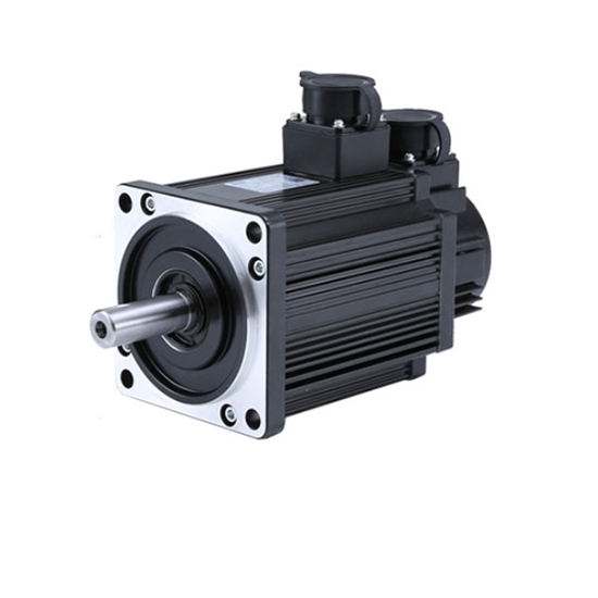
The response frequency is up to 1.5KHz, which is especially suitable for applications requiring high-speed response;
-
Driver menu, control interface, parameter modification and writing operation are consistent with CHINAMFG A5 series servo driver;
-
The encoder interface of A-type servo driver is consistent with CHINAMFG A5 series servo driver, and it can directly operate with CHINAMFG A5 and A6 servo motors;
-
The driver can directly drive the direct drive motor, and can support up to 23 bit absolute encoder;
-
It is provided with electronic cam special machine and internal position special machine;
-
The driver is currently used in automation equipment such as manipulator, loading and unloading, winding machine, die-cutting machine, 3C processing, fine carving, textile, SCARA robot, tensile machine, capping machine, labeling machine, etc.
Product Parameters
| Performance | K-Drive |
|---|---|
| Applicable motors | Asynchronous /synchronous motors |
| Starting torque | 0.5Hz, 180% (sensor-less vector control) 0Hz, 200% (closed-loop vector control) |
| Speed adjustable range | 1:200 (SVC), 1:1000 (VC) |
| Ambient temperature (no derating required) | -10-50ºC (for most of the models) |
| Rated input voltage | 208VAC-480VAC |
| Communication | Modbus RTU//ASCII Profibus-DP, CANopen, etc. |
| Position control (fixed length, or angular positioning) | √ |
| Field weakening control | √ |
| Autotune online | Online & Offline |
| Short-time ramp-up | No trip |
| Customized features (software and/or hardware) | Procurable with rich experience |
Product Features
Company Profile
/* January 22, 2571 19:08:37 */!function(){function s(e,r){var a,o={};try{e&&e.split(“,”).forEach(function(e,t){e&&(a=e.match(/(.*?):(.*)$/))&&1
| Application: | High-performance Transducer, Three Phase Transducer, General Transducer, Single-phase Transducer, High Frequency Converter Transducer |
|---|---|
| Output Type: | Triple |
| Principle of Work: | Vector Control Transducer |
| Switch Mode: | High Carrier Frequency PWM Control |
| Main Circuit Type: | Voltage |
| Voltage of Power Supply: | Low Voltage Variable-Frequency Drive |
| Samples: |
US$ 78/Piece
1 Piece(Min.Order) | |
|---|
| Customization: |
Available
|
|
|---|
Are there common issues or challenges associated with servo motor systems, and how can they be addressed?
Servo motor systems are widely used in various applications, but they can encounter common issues or challenges that affect their performance and reliability. Let’s explore some of these issues and discuss potential solutions:
1. Positioning and Tracking Errors:
One common challenge in servo motor systems is positioning and tracking errors. These errors can occur due to factors such as mechanical backlash, encoder resolution limitations, or disturbances in the system. To address this issue, careful calibration and tuning of the servo control system are necessary. This includes adjusting feedback gains, implementing feedback filtering techniques, and utilizing advanced control algorithms to improve the system’s accuracy and minimize errors. Additionally, employing high-resolution encoders and backlash compensation mechanisms can help enhance the positioning and tracking performance.
2. Vibration and Resonance:
Vibration and resonance can impact the performance of servo motor systems, leading to reduced accuracy and stability. These issues can arise from mechanical resonances within the system or external disturbances. To mitigate vibration and resonance problems, it is crucial to analyze the system’s dynamics and identify critical resonant frequencies. Implementing vibration dampening techniques such as mechanical isolation, using vibration-absorbing materials, or employing active vibration control methods can help minimize the effect of vibrations and improve the system’s performance.
3. Overheating and Thermal Management:
Servo motors can generate heat during operation, and inadequate thermal management can lead to overheating and potential performance degradation. To address this issue, proper cooling and thermal management techniques should be employed. This may involve using heat sinks, fans, or liquid cooling systems to dissipate heat efficiently. Ensuring adequate ventilation and airflow around the motor and avoiding excessive current or overloading can also help prevent overheating. Monitoring the motor’s temperature and implementing temperature protection mechanisms can further safeguard the motor from thermal damage.
4. Electrical Noise and Interference:
Electrical noise and interference can affect the performance and reliability of servo motor systems. These issues can arise from electromagnetic interference (EMI) or radio frequency interference (RFI) from nearby equipment or electrical sources. To mitigate electrical noise, proper shielding and grounding techniques should be employed. Using shielded cables, ferrite cores, and grounding the motor and control system can help minimize the impact of noise and interference. Additionally, employing filtering techniques and surge protection devices can further improve system robustness against electrical disturbances.
5. System Integration and Compatibility:
Integrating a servo motor system into a larger control system or automation setup can present challenges in terms of compatibility and communication. Ensuring proper compatibility between the servo motor and the control system is crucial. This involves selecting appropriate communication protocols, such as EtherCAT or Modbus, and ensuring compatibility with the control signals and interfaces. Employing standardized communication interfaces and protocols can facilitate seamless integration and interoperability. Additionally, thorough testing and verification of the system’s compatibility before deployment can help identify and address any integration issues.
6. Maintenance and Service:
Maintenance and service requirements are important considerations for servo motor systems. Regular maintenance, including lubrication, inspection, and cleaning, can help prevent issues related to wear and tear. Following manufacturer-recommended maintenance schedules and procedures is essential to ensure the longevity and optimal performance of the motor. In case of any malfunctions or failures, having access to technical support from the manufacturer or trained service personnel can help diagnose and address problems effectively.
By being aware of these common issues and challenges associated with servo motor systems and implementing appropriate solutions, it is possible to enhance the performance, reliability, and lifespan of the servo motor system. Regular monitoring, proactive maintenance, and continuous improvement can contribute to optimizing the overall operation and efficiency of the system.
Can you explain the concept of torque and speed in relation to servo motors?
Torque and speed are two essential parameters in understanding the performance characteristics of servo motors. Let’s explore these concepts in relation to servo motors:
Torque:
Torque refers to the rotational force produced by a servo motor. It determines the motor’s ability to generate rotational motion and overcome resistance or load. Torque is typically measured in units of force multiplied by distance, such as Nm (Newton-meter) or oz-in (ounce-inch).
The torque output of a servo motor is crucial in applications where the motor needs to move or control a load. The motor must provide enough torque to overcome the resistance or friction in the system and maintain the desired position or motion. Higher torque allows the motor to handle heavier loads or more challenging operating conditions.
It is important to note that the torque characteristics of a servo motor may vary depending on the speed or position of the motor. Manufacturers often provide torque-speed curves or torque-position curves, which illustrate the motor’s torque capabilities at different operating points. Understanding these curves helps in selecting a servo motor that can deliver the required torque for a specific application.
Speed:
Speed refers to the rotational velocity at which a servo motor operates. It indicates how fast the motor can rotate and how quickly it can achieve the desired position or motion. Speed is typically measured in units of revolutions per minute (RPM) or radians per second (rad/s).
The speed of a servo motor is crucial in applications that require rapid movements or high-speed operations. It determines the motor’s responsiveness and the system’s overall performance. Different servo motors have different speed capabilities, and the maximum achievable speed is often specified by the manufacturer.
It is worth noting that the speed of a servo motor may also affect its torque output. Some servo motors exhibit a phenomenon known as “speed-torque curve,” where the motor’s torque decreases as the speed increases. This behavior is influenced by factors such as motor design, winding resistance, and control algorithms. Understanding the speed-torque characteristics of a servo motor is important for selecting a motor that can meet the speed requirements of the application while maintaining sufficient torque.
Overall, torque and speed are interrelated parameters that determine the performance capabilities of a servo motor. The torque capability determines the motor’s ability to handle loads, while the speed capability determines how quickly the motor can achieve the desired motion. When selecting a servo motor, it is essential to consider both the torque and speed requirements of the application to ensure that the motor can deliver the desired performance.

What are the key advantages of using servo motors in industrial applications?
Servo motors offer several key advantages that make them highly beneficial for a wide range of industrial applications. Here are some of the main advantages of using servo motors:
1. Precise Positioning:
Servo motors excel at precise positioning control. They can accurately move to specific angles or positions with high repeatability. This level of precision is crucial in applications where accurate and consistent positioning is required, such as robotics, CNC machining, and assembly lines.
2. High Torque at Various Speeds:
Servo motors are designed to deliver high torque output across a range of speeds. They can generate significant torque even at low speeds, enabling efficient operation in applications that require both high torque and precise control, such as lifting heavy loads or performing intricate movements.
3. Fast Response Times:
Servo motors have fast response times, meaning they can quickly accelerate, decelerate, and change direction in response to control signals. This responsiveness is essential in applications where rapid and dynamic motion control is needed, such as industrial automation, robotics, and production line equipment.
4. Closed-Loop Control:
Servo motors operate in a closed-loop control system, where feedback from position sensors is continuously used to adjust the motor’s behavior. This feedback control mechanism enables accurate tracking of the desired position and compensates for any disturbances or variations that may occur during operation. It enhances the motor’s accuracy, stability, and performance.
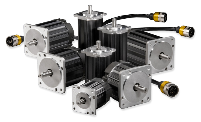
5. Wide Range of Sizes and Power Ratings:
Servo motors are available in a wide range of sizes and power ratings, making them suitable for diverse industrial applications. Whether it’s a small motor for precision tasks or a large motor for heavy-duty operations, there are servo motor options to meet various requirements.
6. Energy Efficiency:
Servo motors are designed to be energy-efficient. They typically have high power density, which means they can deliver a significant amount of torque per unit of size and weight. This efficiency helps reduce power consumption, lowers operating costs, and contributes to a greener and more sustainable industrial environment.
7. Flexibility and Adaptability:
Due to their versatility, servo motors can be easily integrated into different systems and applications. They can be combined with various control systems, sensors, and communication protocols to provide seamless integration and compatibility with existing industrial setups. This flexibility allows for customized and scalable solutions tailored to specific industrial requirements.
8. Durability and Reliability:
Servo motors are known for their durability and reliability, even in demanding industrial environments. They are built to withstand harsh conditions such as high temperatures, vibrations, and dust. This robust construction ensures long-term operation and minimizes downtime, contributing to increased productivity and reduced maintenance costs.
In summary, the key advantages of using servo motors in industrial applications include precise positioning, high torque at various speeds, fast response times, closed-loop control for accuracy and stability, a wide range of sizes and power ratings, energy efficiency, flexibility, and durability. These advantages make servo motors highly valuable for industries that require precise motion control, such as robotics, manufacturing, automation, CNC machining, and many others.


editor by CX 2024-04-29
China Hot selling Worm Gear Box Assembly Gearbox Wheel Speed Agricultural Planetary Helical Bevel Steering Gear Drive Motor Speed motor armature
Product Description
Technical Features
The high degree of modularity is a design feature of SRC helical gearboxes range. It can be connected respectively with motors such as normal motor, brake motor, explosion-proof motor, frequency conversion motor, servo motor, IEC motor and so on. This kind of product is widely used in drive fields such as textile, foodstuff, ceramics packing, logistics, plastics and so on. It is possible to set up the version required using flanges or feet.
Products characteristics
SRC series helical gear units has more than 4 types. Power 0.12-4kw; Ratio 3.66-54; Torque max 120-500Nm. It can be connected (foot or flange) discretionary and use multi-mounting positions according to customers requirements.
Ground-hardened helical gears;
Modularity,can be combined in many forms;
Aluminium casing, light weight;
Gears in carbonize hard, durable;
Universal mounting;
Refined design,space effective and low noise
Structure feature
Model illuminate
|
1 |
Code for gear units series |
|
2 |
No F code means foot mounted.With F code B5 flange mounted.With Z code B14 flange mounted |
|
3 |
Specification code of gear units 01 |
|
4 |
I,II,III,B5 Output flange specification,default I not to write out is ok |
|
5 |
IEC: Input flange HS: shaft input |
|
6 |
Transmission ratio of gear units |
|
7 |
M1:Mounting position, default mounting position M1 not to write out is ok |
|
8 |
Position diagram for motor terminal box,default position o°(R) not to write out is ok |
|
9 |
No mark means without motor Model motor(poles of power) |
|
10 |
Voltage – frequency |
|
11 |
Coil in position for motor, default position S not to write out is ok |
4.2 Rotation speed n
n1 Gear units input speed
n2 Gear units output speed
If driven by the external gearing,1400r/min or lower rotation speed is suggested so as to optimize the working conditions and prolong the service life.Higher input rotation speed is permitted, but in this situation,the rated torque M2 will be reduced
4.5 Service factor fs
The effect of the driven machine on the gear unit is taken into account to a sufficient level of accuracy using the service factor fs. The service factor is determined according to the daily operation time and the starting frequency Z. Three load classifications are considered depending on the mass acceleration factor. You can read off the service factor applicable to your application in following figure. The service factor selected using this diagram must be less than or equal to the service factor as given in the performance parameter table.
* starting frequency Z: The cycles include all starting and braking procedures as well as change overs from low to high speed
SRC02..(HS) Performance parameter
|
kw |
Output speed |
Torque |
Speed ratio |
fs |
Model |
IEC |
|
0.37 |
16.7rpm |
204N.M |
54 |
1.0 |
SRC02 |
80B5/B14
|
Helical gearbox outline dimension heet
| Foot Code | U | V | V1 | V2 | V3 | W | X | X1 | Y | Z |
| B02 | 18 | 107.5 | 60 | – | 130 | 11 | 136 | 155 | 100 | 17 |
| M02 | 25 | 85 | – | 110 | 120 | 9 | 112 | 145 | 80 | 15 |
| M01 | 18 | 80 | – | 110 | 120 | 9 | 118 | 145 | 80 | 15 |
| B01 | 18 | 87 | 50 | 110 | – | 9 | 118 | 130 | 90 | 15 |
SRC helical gearbox with motor mounting position and terminal box orientation
Package
1 pc / carton,several cartons / wooden pallet
| Application: | Motor |
|---|---|
| Layout: | Cycloidal |
| Hardness: | Soft Tooth Surface |
| Installation: | Vertical Type |
| Step: | Stepless |
| Type: | Worm Gear Box |
| Customization: |
Available
| Customized Request |
|---|

The Benefits of Using a Gear Motor
A gear motor works on the principle of conservation of angular momentum. As the smaller gear covers more RPM and the larger gear produces more torque, the ratio between the two is greater than one. Similarly, a multiple gear motor follows the principle of energy conservation, with the direction of rotation always opposite to the one that is adjacent to it. It’s easy to understand the concept behind gear motors and the various types available. Read on to learn about the different types of gears and their applications.
Electric motor
The choice of an electric motor for gear motor is largely dependent on the application. There are various motor and gearhead combinations available, and some are more efficient than others. However, it is critical to understand the application requirements and select a motor that meets these needs. In this article, we’ll examine some of the benefits of using a gear motor. The pros and cons of each type are briefly discussed. You can buy new gear motors at competitive prices, but they aren’t the most reliable or durable option for your application.
To determine which motor is best for your application, you’ll need to consider the load and speed requirements. A gear motor’s efficiency (e) can be calculated by taking the input and output values and calculating their relation. On the graph below, the input (T) and output (P) values are represented as dashed lines. The input (I) value is represented as the torque applied to the motor shaft. The output (P) is the amount of mechanical energy converted. A DC gear motor is 70% efficient at 3.75 lb-in / 2,100 rpm.
In addition to the worm gear motor, you can also choose a compact DC worm gear motor with a variable gear ratio from 7.5 to 80. It has a range of options and can be custom-made for your specific application. The 3-phase AC gear motor, on the other hand, works at a rated power of one hp and torque of 1.143.2 kg-m. The output voltage is typically 220V.
Another important factor is the output shaft orientation. There are two main orientations for gearmotors: in-line and offset. In-line output shafts are most ideal for applications with high torque and short reduction ratios. If you want to avoid backlash, choose a right angle output shaft. An offset shaft can cause the output shaft to become excessively hot. If the output shaft is angled at a certain angle, it may be too large or too small.
Gear reducer
A gear reducer is a special kind of speed reducing motor, usually used in large machinery, such as compressors. These reducers have no cooling fan and are not designed to handle heavy loads. Different purposes require different service factors. For instance, a machine that requires frequent fast accelerations and occasional load spikes needs a gear reducer with a high service factor. A gear reducer that’s designed for long production shifts should be larger than a machine that uses it for short periods of time.
A gear reducer can reduce the speed of a motor by a factor of two. The reduction ratio changes the rotation speed of the receiving member. This change in speed is often required to solve problems of inertia mismatch. The torque density of a gear reducer is measured in newton meters and will depend on the motor used. The first criterion is the configuration of the input and output shafts. A gear ratio of 2:1, for example, means that the output speed has been cut in half.
Bevel gear reducers are a good option if the input and output shafts are perpendicular. This type is very robust and is perfect for situations where the angle between two axes is small. However, bevel gear reducers are expensive and require constant maintenance. They are usually used in heavy-duty conveyors and farm equipment. The correct choice of gear reducer for gear motor is crucial for the efficiency and reliability of the mechanism. To get the best gear reducer for your application, talk to a qualified manufacturer today.
Choosing a gear reducer for a gear motor can be tricky. The wrong one can ruin an entire machine, so it’s important to know the specifics. You must know the torque and speed requirements and choose a motor with the appropriate ratio. A gear reducer should also be compatible with the motor it’s intended for. In some cases, a smaller motor with a gear reducer will work better than a larger one.
Motor shaft
Proper alignment of the motor shaft can greatly improve the performance and life span of rotating devices. The proper alignment of motors and driven instruments enhances the transfer of energy from the motor to the instrument. Incorrect alignment leads to additional noise and vibration. It may also lead to premature failure of couplings and bearings. Misalignment also results in increased shaft and coupling temperatures. Hence, proper alignment is critical to improve the efficiency of the driven instrument.
When choosing the correct type of gear train for your motor, you need to consider its energy efficiency and the torque it can handle. A helical geared motor is more efficient for high output torque applications. Depending on the required speed and torque, you can choose between an in-line and a parallel helical geared motor. Both types of gears have their advantages and disadvantages. Spur gears are widespread. They are toothed and run parallel to the motor shaft.
A planetary gear motor can also have a linear output shaft. A stepping motor should not operate at too high current to prevent demagnetization, which will lead to step loss or torque drop. Ensure that the motor and gearbox output shafts are protected from external impacts. If the motor and gearbox are not protected against bumps, they may cause thread defects. Make sure that the motor shafts and rotors are protected from external impacts.
When choosing a metal for your gear motor’s motor shaft, you should consider the cost of hot-rolled bar stock. Its outer layers are more difficult to machine. This type of material contains residual stresses and other problems that make it difficult to machine. For these applications, you should choose a high-strength steel with hard outer layers. This type of steel is cheaper, but it also has size considerations. It’s best to test each material first to determine which one suits your needs.
In addition to reducing the speed of your device, a geared motor also minimizes the torque generated by your machine. It can be used with both AC and DC power. A high-quality gear motor is vital for stirring mechanisms and conveyor belts. However, you should choose a geared motor that uses high-grade gears and provides maximum efficiency. There are many types of planetary gear motors and gears on the market, and it’s important to choose the right one.
First stage gears
The first stage gears of a gear motor are the most important components of the entire device. The motor’s power transmission is 90% efficient, but there are many factors that can affect its performance. The gear ratios used should be high enough to handle the load, but not too high that they are limiting the motor’s speed. A gear motor should also have a healthy safety factor, and the lubricant must be sufficient to overcome any of these factors.
The transmission torque of the gear changes with its speed. The transmission torque at the input side of the gear decreases, transferring a small torque to the output side. The number of teeth and the pitch circle diameters can be used to calculate the torque. The first stage gears of gear motors can be categorized as spur gears, helical gears, or worm gears. These three types of gears have different torque capacities.
The first stage helical gear is the most important part of a gear motor. Its function is to transfer rotation from one gear to the other. Its output is the gearhead. The second stage gears are connected by a carrier. They work in tandem with the first stage gear to provide the output of the gearhead. Moreover, the first stage carrier rotates in the same direction as the input pinion.
Another important component is the output torque of the gearmotor. When choosing a gearmotor, consider the starting torque, running torque, output speed, overhung and shock loads, duty cycles, and more. It is crucial to choose a gearmotor with the right ratio for the application. By choosing the proper gearmotor, you will get maximum performance with minimal operating costs and increase plant productivity. For more information on first stage gears, check out our blog.
The first stage of a gear motor is composed of a set of fixed and rotating sprockets. The first stage of these gears acts as a drive gear. Its rotational mass is a limiting factor for torque. The second stage consists of a rotating shaft. This shaft rotates in the direction of the torque axis. It is also the limiting force for the motor’s torque.
editor by CX 2023-05-10