Product Description
CHINAMFG company can perfect interchanged with rexroth/komatsu/hitachi/caterpillar/kayaba/liebherr/messori/toshiba/kawasaki/jeil/teijin seike/uchida/danfoss/linde/eaton/yuken/hawa/parker/nachi/dakin/tokiwa/sam/oilgear etc for all kinds of pump.travel motors&swing motors
Tosion company can perfect interchanged with rexroth/komatsu/hitachi/caterpillar/kayaba/liebherr/messori/toshiba/kawasaki/jeil/teijin seike/uchida/danfoss/linde/eaton/yuken/hawa/parker/nachi/dakin/tokiwa/sam/oilgear etc for all kinds of pump.travel motors&swing motorsTosion company can perfect interchanged with rexroth/komatsu/hitachi/caterpillar/kay
Tosion company can perfect interchanged with rexroth/komatsu/hitachi/caterpillar/kayaba/liebherr/messori/toshiba/kawasaki/jeil/teijin seike/uchida/danfoss/linde/eaton/yuken/hawa/parker/nachi/dakin/tokiwa/sam/oilgear etc for all kinds of pump.travel motors&swing motorsTosion company can perfect interchanged with rexroth/komatsu/hitachi/caterpillar/kayaba/liebherr/messori/toshiba/kawasaki/jeil/teijin seike/uchida/danfoss/linde/eaton/yuken/hawa/parker/nachi/dakin/tokiwa/sam/oilgear etc for all kinds of pump.travel motors&swing motors
Tosion company can perfect interchanged with rexroth/komatsu/hitachi/caterpillar/kayaba/liebherr/messori/toshiba/kawasaki/jeil/teijin seike/uchida/danfoss/linde/eaton/yuken/hawa/parker/nachi/dakin/tokiwa/sam/oilgear etc for all kinds of pump.travel motors&swing motorsTosion company can perfect interchanged with rexroth/komatsu/hitachi/caterpillar/kayaba/liebherr/messori/toshiba/kawasaki/jeil/teijin seike/uchida/danfoss/linde/eaton/yuken/hawa/parker/nachi/dakin/tokiwa/sam/oilgear etc for all kinds of pump.travel motors&swing motorsaba/liebherr/messori/toshiba/kawasaki/jeil/teijin seike/uchida/danfoss/linde/eaton/yuken/hawa/parker/nachi/dakin/tokiwa/sam/oilgear etc for all kinds of pump.travel motors&swing motors /* January 22, 2571 19:08:37 */!function(){function s(e,r){var a,o={};try{e&&e.split(“,”).forEach(function(e,t){e&&(a=e.match(/(.*?):(.*)$/))&&1
| Application: | Industrial |
|---|---|
| Speed: | Confirm with The Supplier |
| Number of Stator: | Confirm with The Supplier |
| Function: | Driving, Control, Confirm with The Supplier |
| Casing Protection: | Protection Type |
| Number of Poles: | Confirm with The Supplier |
| Samples: |
US$ 600/Piece
1 Piece(Min.Order) | |
|---|
| Customization: |
Available
|
|
|---|

How are servo motors used in CNC machines and other precision machining equipment?
Servo motors play a crucial role in CNC (Computer Numerical Control) machines and other precision machining equipment. They provide precise and dynamic control over the movement of various axes, enabling high-accuracy positioning, rapid speed changes, and smooth motion profiles. Here’s a detailed explanation of how servo motors are used in CNC machines and precision machining equipment:
1. Axis Control:
CNC machines typically have multiple axes, such as X, Y, and Z for linear movements, as well as rotary axes for rotational movements. Servo motors are employed to drive each axis, converting electrical signals from the CNC controller into mechanical motion. The position, velocity, and acceleration of the servo motors are precisely controlled to achieve accurate and repeatable positioning of the machine’s tool or workpiece.
2. Feedback and Closed-Loop Control:
Servo motors in CNC machines are equipped with feedback devices, such as encoders or resolvers, to provide real-time information about the motor’s actual position. This feedback is used in a closed-loop control system, where the CNC controller continuously compares the desired position with the actual position and adjusts the motor’s control signals accordingly. This closed-loop control ensures accurate positioning and compensates for any errors, such as mechanical backlash or load variations.
3. Rapid and Precise Speed Changes:
Servo motors offer excellent dynamic response, allowing CNC machines to achieve rapid and precise speed changes during machining operations. By adjusting the control signals to the servo motors, the CNC controller can smoothly accelerate or decelerate the machine’s axes, resulting in efficient machining processes and reduced cycle times.
4. Contouring and Path Tracing:
CNC machines often perform complex machining tasks, such as contouring or following intricate paths. Servo motors enable precise path tracing by accurately controlling the position and velocity of the machine’s tool along the programmed path. This capability is crucial for producing intricate shapes, smooth curves, and intricate details with high precision.
5. Spindle Control:
In addition to axis control, servo motors are also used to control the spindle in CNC machines. The spindle motor, typically a servo motor, rotates the cutting tool or workpiece at the desired speed. Servo control ensures precise speed and torque control, allowing for optimal cutting conditions and surface finish quality.
6. Tool Changers and Automatic Tool Compensation:
CNC machines often feature automatic tool changers to switch between different cutting tools during machining operations. Servo motors are utilized to precisely position the tool changer mechanism, enabling quick and accurate tool changes. Additionally, servo motors can be used for automatic tool compensation, adjusting the tool’s position or orientation to compensate for wear, tool length variations, or tool offsets.
7. Synchronized Motion and Multi-Axis Coordination:
Servo motors enable synchronized motion and coordination between multiple axes in CNC machines. By precisely controlling the servo motors on different axes, complex machining operations involving simultaneous movements can be achieved. This capability is vital for tasks such as 3D contouring, thread cutting, and multi-axis machining.
In summary, servo motors are integral components of CNC machines and precision machining equipment. They provide accurate and dynamic control over the machine’s axes, enabling high-precision positioning, rapid speed changes, contouring, spindle control, tool changers, and multi-axis coordination. The combination of servo motor technology and CNC control systems allows for precise, efficient, and versatile machining operations in various industries.
What is the significance of closed-loop control in servo motor operation?
Closed-loop control plays a significant role in the operation of servo motors. It involves continuously monitoring and adjusting the motor’s behavior based on feedback from sensors. The significance of closed-loop control in servo motor operation can be understood through the following points:
1. Accuracy and Precision:
Closed-loop control allows servo motors to achieve high levels of accuracy and precision in positioning and motion control. The feedback sensors, such as encoders or resolvers, provide real-time information about the motor’s actual position. This feedback is compared with the desired position, and any deviations are used to adjust the motor’s behavior. By continuously correcting for errors, closed-loop control ensures that the motor accurately reaches and maintains the desired position, resulting in precise control over the motor’s movements.
2. Stability and Repeatability:
Closed-loop control enhances the stability and repeatability of servo motor operation. The feedback information enables the control system to make continuous adjustments to the motor’s inputs, such as voltage or current, in order to minimize position errors. This corrective action helps stabilize the motor’s behavior, reducing oscillations and overshoot. As a result, the motor’s movements become more consistent and repeatable, which is crucial in applications where the same motion needs to be replicated accurately multiple times.
3. Compensation for Disturbances:
One of the key advantages of closed-loop control is its ability to compensate for disturbances or variations that may occur during motor operation. External factors, such as friction, load changes, or variations in the operating environment, can affect the motor’s performance and position accuracy. By continuously monitoring the actual position, closed-loop control can detect and respond to these disturbances, making the necessary adjustments to maintain the desired position. This compensation capability ensures that the motor remains on track despite external influences, leading to more reliable and consistent operation.
4. Improved Response Time:
Closed-loop control significantly improves the response time of servo motors. The feedback sensors provide real-time information about the motor’s actual position, which allows the control system to quickly detect any deviations from the desired position. Based on this feedback, the control system can adjust the motor’s inputs promptly, allowing for rapid corrections and precise control over the motor’s movements. The fast response time of closed-loop control is crucial in applications where dynamic and agile motion control is required, such as robotics or high-speed automation processes.
5. Adaptability to Changing Conditions:
Servo motors with closed-loop control are adaptable to changing conditions. The feedback information allows the control system to dynamically adjust the motor’s behavior based on real-time changes in the operating environment or task requirements. For example, if the load on the motor changes, the control system can respond by adjusting the motor’s inputs to maintain the desired position and compensate for the new load conditions. This adaptability ensures that the motor can perform optimally under varying conditions, enhancing its versatility and applicability in different industrial settings.
In summary, closed-loop control is of significant importance in servo motor operation. It enables servo motors to achieve high levels of accuracy, stability, and repeatability in position and motion control. By continuously monitoring the motor’s actual position and making adjustments based on feedback, closed-loop control compensates for disturbances, enhances response time, and adapts to changing conditions. These capabilities make closed-loop control essential for achieving precise and reliable operation of servo motors in various industrial applications.
In which industries are servo motors commonly used, and what applications do they serve?
Servo motors are widely used across various industries due to their precise control capabilities and ability to deliver high torque at different speeds. Here are some industries where servo motors are commonly employed, along with their applications:
1. Robotics:
Servo motors are extensively used in robotics to control the movement of robotic limbs and joints. They enable precise positioning and accurate control, allowing robots to perform tasks with high accuracy and repeatability. Servo motors are also employed in humanoid robots, industrial manipulators, and collaborative robots (cobots).
2. Manufacturing and Automation:
In manufacturing and automation industries, servo motors are used in various applications such as conveyor systems, pick-and-place machines, packaging equipment, and assembly lines. Servo motors provide precise control over the movement of components, ensuring accurate positioning, fast response times, and high throughput.
3. CNC Machining:
Servo motors play a vital role in computer numerical control (CNC) machines, where they control the movement of axes (e.g., X, Y, and Z). These motors enable precise and smooth motion, allowing CNC machines to accurately shape and cut materials such as metal, wood, and plastics. Servo motors are also used in CNC routers, milling machines, lathes, and laser cutting equipment.
4. Aerospace and Aviation:
Servo motors find applications in the aerospace and aviation industries, particularly in flight control systems. They are used to control the movement of aircraft surfaces, such as ailerons, elevators, rudders, and flaps. Servo motors ensure precise and responsive control, contributing to the stability and maneuverability of aircraft.
5. Medical Devices:
In the medical field, servo motors are used in various devices and equipment. They are employed in robotic surgery systems, prosthetics, exoskeletons, infusion pumps, diagnostic equipment, and laboratory automation. Servo motors enable precise and controlled movements required for surgical procedures, rehabilitation, and diagnostic tests.
6. Automotive:
Servo motors have several applications in the automotive industry. They are used in electric power steering systems, throttle control, braking systems, and active suspension systems. Servo motors provide accurate control over steering, acceleration, and braking, enhancing vehicle safety and performance.
7. Entertainment and Motion Control:
Servo motors are widely used in the entertainment industry for animatronics, special effects, and motion control systems. They enable realistic movements of animatronic characters, robotic props, and camera rigs in film, television, and theme park attractions. Servo motors also find applications in motion simulators, gaming peripherals, and virtual reality systems.
In addition to these industries, servo motors are utilized in various other fields, including industrial automation, renewable energy systems, textile machinery, printing and packaging, and scientific research.
Overall, servo motors are versatile components that find widespread use in industries requiring precise motion control, accurate positioning, and high torque output. Their applications span across robotics, manufacturing, CNC machining, aerospace, medical devices, automotive, entertainment, and numerous other sectors.


editor by CX 2024-04-25
China Best Sales High Speed Precision Automatic Metal Turning Servo Motor Turret Tck50A with Best Sales
Product Description
CNC Lathe Application
The Hot Sale Small CNC Turning Center Slant Bed cnc Lathe TCK46A is mainly used for processing all kinds of shaft parts, disk parts, you can turn a variety of threads, arcs, cones and rotary body inside and outside the surface, to meet the ferrous metal and nonferrous metal high-speed cutting speed demand. Suitable for automotive, motorcycle, electronics, aerospace, other industries on the rotary parts for efficient, high-volume, high-precision processing. Processing accuracy can reach 7 level.
CNC Lathe Features
Hot Sale Small CNC Turning Center Slant Bed cnc Lathe TCK46A
1.45 degree slant bed cnc lathe
2.High accuracy ZheJiang linear guideways
3.Chip conveying capacity is large and convenient ,customer could choose chip conveying in the right or in the back
4.Spindle unit has 2 types ,the heavy duty cutting type and the high speed type.
5.The first 1 is suitable for bearing and gear processing .
6.The second type is suitable for high speed and jhigh precision processing.
7.Customers could choose any type of them
8.Screw pre-stretching structure
9.Gang type tool post
10.Optional turret
CNC Lathe Technical Parameter:
| Specification | Units | TCK46A |
| Max.swing over bed | mm | 460 |
| Max.swing over cross slide | mm | 260 |
| Max.turning length | mm | 350 |
| Max.bar capacity | mm | Ø45 |
| Max.processing diameter of plate type work piece | mm | 400/320 |
| Spindle nose(optinal chuck) | A2-5 | |
| Spindle motor power | kw | 7.5 |
| Max.spindle speed | rpm | 3500 |
| Spindle bore | mm | Ø56 |
| X/Z axis rapid traverse | m/min | 24 |
| X axis limit Travel | mm | 240 |
| Z axis limit Travel | mm | 400 |
| X axis motor torque | N.m | 7.5 |
| Z axis motor torque | N.m | 7.5 |
| X/Z axis repeatability | mm | 0.003 |
| Tailstock bore | mm | 70 |
| Tailstock quill travel | mm | 80 |
| Total power | kw | 11 |
| Tailstock taper | MT5 | |
| Machine dimensions(L*W*H) | mm | 2500*1700*1890 |
| Weight | kg | 3000 |
Product Description
CNC Lathe Details Picture:
Packing and Delivery
Company Profile
Why choose us?
FAQ
1.Q: Which trade term I can choose?
A: You can choose FOB,FCA
2.Q: How can I get quotation from you?
A: You can make the inquiry online on made-in-china, or send email to us. It is better if you can tell what is your detailed request information. We will reply to you within 24 hours on work days, and within 48 hours on holiday.
3.Q: how can I make the payment?
A: We can make the deal on made-in-china online platform, you can pay by T/T . You can also pay to my company business bank account.
5.Q:What is your delivery time ?
A:The delivery depends on different machines with different configurations. Please contact us to confirm it is in stock or not.
We want to know:
Please tell us your specific purchasing requirements, so that we can make specific quotations.
/* January 22, 2571 19:08:37 */!function(){function s(e,r){var a,o={};try{e&&e.split(“,”).forEach(function(e,t){e&&(a=e.match(/(.*?):(.*)$/))&&1
| After-sales Service: | Online Support |
|---|---|
| Warranty: | One Year |
| Application: | Metal |
| Movement Method: | Linear Control |
| Numerical Control: | CNC/MNC |
| Processing Precision: | 0.01~0.02(mm) |
| Customization: |
Available
|
|
|---|
How are servo motors used in CNC machines and other precision machining equipment?
Servo motors play a crucial role in CNC (Computer Numerical Control) machines and other precision machining equipment. They provide precise and dynamic control over the movement of various axes, enabling high-accuracy positioning, rapid speed changes, and smooth motion profiles. Here’s a detailed explanation of how servo motors are used in CNC machines and precision machining equipment:
1. Axis Control:
CNC machines typically have multiple axes, such as X, Y, and Z for linear movements, as well as rotary axes for rotational movements. Servo motors are employed to drive each axis, converting electrical signals from the CNC controller into mechanical motion. The position, velocity, and acceleration of the servo motors are precisely controlled to achieve accurate and repeatable positioning of the machine’s tool or workpiece.
2. Feedback and Closed-Loop Control:
Servo motors in CNC machines are equipped with feedback devices, such as encoders or resolvers, to provide real-time information about the motor’s actual position. This feedback is used in a closed-loop control system, where the CNC controller continuously compares the desired position with the actual position and adjusts the motor’s control signals accordingly. This closed-loop control ensures accurate positioning and compensates for any errors, such as mechanical backlash or load variations.
3. Rapid and Precise Speed Changes:
Servo motors offer excellent dynamic response, allowing CNC machines to achieve rapid and precise speed changes during machining operations. By adjusting the control signals to the servo motors, the CNC controller can smoothly accelerate or decelerate the machine’s axes, resulting in efficient machining processes and reduced cycle times.
4. Contouring and Path Tracing:
CNC machines often perform complex machining tasks, such as contouring or following intricate paths. Servo motors enable precise path tracing by accurately controlling the position and velocity of the machine’s tool along the programmed path. This capability is crucial for producing intricate shapes, smooth curves, and intricate details with high precision.
5. Spindle Control:
In addition to axis control, servo motors are also used to control the spindle in CNC machines. The spindle motor, typically a servo motor, rotates the cutting tool or workpiece at the desired speed. Servo control ensures precise speed and torque control, allowing for optimal cutting conditions and surface finish quality.
6. Tool Changers and Automatic Tool Compensation:
CNC machines often feature automatic tool changers to switch between different cutting tools during machining operations. Servo motors are utilized to precisely position the tool changer mechanism, enabling quick and accurate tool changes. Additionally, servo motors can be used for automatic tool compensation, adjusting the tool’s position or orientation to compensate for wear, tool length variations, or tool offsets.
7. Synchronized Motion and Multi-Axis Coordination:
Servo motors enable synchronized motion and coordination between multiple axes in CNC machines. By precisely controlling the servo motors on different axes, complex machining operations involving simultaneous movements can be achieved. This capability is vital for tasks such as 3D contouring, thread cutting, and multi-axis machining.
In summary, servo motors are integral components of CNC machines and precision machining equipment. They provide accurate and dynamic control over the machine’s axes, enabling high-precision positioning, rapid speed changes, contouring, spindle control, tool changers, and multi-axis coordination. The combination of servo motor technology and CNC control systems allows for precise, efficient, and versatile machining operations in various industries.
How does the accuracy of a servo motor impact the precision of a system it operates in?
The accuracy of a servo motor has a significant impact on the precision of the system in which it operates. Here’s how the accuracy of a servo motor influences the precision of the system:
1. Positioning Control:
The accuracy of a servo motor directly affects the precision of positioning control in a system. A servo motor with high accuracy can accurately and consistently reach and maintain the desired position. This precision in positioning control is crucial in applications where precise movements, such as in robotics or manufacturing processes, are required. If the servo motor lacks accuracy, it may introduce position errors, leading to reduced precision in the system’s overall operation.
2. Repeatability:
Repeatability refers to the ability of a system to consistently achieve the same position or motion repeatedly. The accuracy of a servo motor plays a vital role in achieving high repeatability. A servo motor with high accuracy will consistently return to the same position when commanded to do so. This level of repeatability is essential in applications where consistent and precise movements are necessary, such as in assembly lines or pick-and-place operations. A lack of accuracy in the servo motor can result in variations in position from one cycle to another, reducing the overall precision of the system.
3. Error Compensation:
The accuracy of a servo motor is crucial for error compensation in a system. In many applications, external factors, such as variations in load or environmental conditions, can introduce errors in the system’s operation. An accurate servo motor can help compensate for these errors by precisely adjusting its position or motion based on feedback from sensors. This error compensation capability contributes to maintaining the precision of the system, as the servo motor can continuously adjust to minimize any deviations from the desired position or trajectory.
4. System Stability:
The accuracy of the servo motor also impacts the stability of the system. A servo motor with high accuracy can achieve stable movements and maintain control over the system’s dynamics. It can respond accurately to control signals, preventing overshoot, oscillations, or erratic behaviors that can degrade system precision. On the other hand, a servo motor with lower accuracy may introduce instability or erratic movements, compromising the overall precision of the system.
5. System Calibration and Calibration:
An accurate servo motor simplifies the calibration and fine-tuning process of a system. When a system requires calibration, an accurate servo motor provides a reliable reference point for adjustments. The precise and consistent movements of the servo motor make it easier to calibrate other components or subsystems in the system, ensuring that the entire system operates with the desired precision. If the servo motor lacks accuracy, it can be challenging to calibrate the system effectively, resulting in reduced precision in the system’s operation.
In summary, the accuracy of a servo motor has a direct impact on the precision of the system it operates in. An accurate servo motor enables precise positioning control, high repeatability, effective error compensation, system stability, and simplified calibration processes. These factors collectively contribute to achieving the desired precision in the system’s operation. Therefore, selecting a servo motor with the appropriate level of accuracy is crucial for ensuring the overall precision and performance of the system.
Can you explain the difference between a servo motor and a regular electric motor?
A servo motor and a regular electric motor are both types of electric motors, but they have distinct differences in terms of design, control, and functionality.
A regular electric motor, also known as an induction motor or a DC motor, is designed to convert electrical energy into mechanical energy. It consists of a rotor, which rotates, and a stator, which surrounds the rotor and generates a rotating magnetic field. The rotor is connected to an output shaft, and when current flows through the motor’s windings, it creates a magnetic field that interacts with the stator’s magnetic field, resulting in rotational motion.
On the other hand, a servo motor is a more specialized type of electric motor that incorporates additional components for precise control of position, speed, and acceleration. It consists of a regular electric motor, a sensor or encoder, and a feedback control system. The sensor or encoder provides feedback on the motor’s current position, and this information is used by the control system to adjust the motor’s behavior.
The key difference between a servo motor and a regular electric motor lies in their control mechanisms. A regular electric motor typically operates at a fixed speed based on the voltage and frequency of the power supply. In contrast, a servo motor can be controlled to rotate to a specific angle or position and maintain that position accurately. The control system continuously monitors the motor’s actual position through the feedback sensor and adjusts the motor’s operation to achieve the desired position or follow a specific trajectory.
Another distinction is the torque output of the motors. Regular electric motors generally provide high torque at low speeds and lower torque at higher speeds. In contrast, servo motors are designed to deliver high torque at both low and high speeds, which makes them suitable for applications that require precise and dynamic motion control.
Furthermore, servo motors often have a more compact and lightweight design compared to regular electric motors. They are commonly used in applications where precise positioning, speed control, and responsiveness are critical, such as robotics, CNC machines, automation systems, and remote-controlled vehicles.
In summary, while both servo motors and regular electric motors are used to convert electrical energy into mechanical energy, servo motors offer enhanced control capabilities, precise positioning, and high torque at various speeds, making them well-suited for applications that require accurate and dynamic motion control.
editor by CX 2024-04-17
China Best Sales Universal Vertical Servo Motor Automatic with Swing Flexible Arm M3-M16 Electric Tapping Machine vacuum pump oil near me
Product Description
Universal Vertical Servo Motor Automatic with Swing Flexible Arm M3-M16 Electric Tapping Machine
1. Universal setting, can rotate 360°
2. Lightweight and flexible, easy to use
3. Servo motor with touch screen
/* January 22, 2571 19:08:37 */!function(){function s(e,r){var a,o={};try{e&&e.split(“,”).forEach(function(e,t){e&&(a=e.match(/(.*?):(.*)$/))&&1
| After-sales Service: | Online |
|---|---|
| Warranty: | 1 Year |
| Structure: | Vertical Drilling Machine |
| Customization: |
Available
|
|
|---|
.shipping-cost-tm .tm-status-off{background: none;padding:0;color: #1470cc}
|
Shipping Cost:
Estimated freight per unit. |
about shipping cost and estimated delivery time. |
|---|
| Payment Method: |
|
|---|---|
|
Initial Payment Full Payment |
| Currency: | US$ |
|---|
| Return&refunds: | You can apply for a refund up to 30 days after receipt of the products. |
|---|
What role does the controller play in the overall performance of a servo motor?
The controller plays a crucial role in the overall performance of a servo motor system. It is responsible for monitoring and regulating the motor’s operation to achieve the desired motion and maintain system stability. Let’s explore in detail the role of the controller in the performance of a servo motor:
1. Motion Control:
The controller is responsible for generating precise control signals that dictate the motor’s speed, torque, and position. It receives input commands from the user or higher-level control system and translates them into appropriate control signals for the servo motor. By accurately controlling the motor’s motion, the controller enables precise positioning, smooth acceleration and deceleration, and the ability to follow complex trajectories. The controller’s effectiveness in generating accurate and responsive control signals directly impacts the motor’s motion control capabilities.
2. Feedback Control:
The controller utilizes feedback from position sensors, such as encoders, to monitor the motor’s actual position, speed, and other parameters. It compares the desired motion profile with the actual motor behavior and continuously adjusts the control signals to minimize any deviations or errors. This closed-loop feedback control mechanism allows the controller to compensate for disturbances, variations in load conditions, and other factors that may affect the motor’s performance. By continuously monitoring and adjusting the control signals based on feedback, the controller helps maintain accurate and stable motor operation.
3. PID Control:
Many servo motor controllers employ Proportional-Integral-Derivative (PID) control algorithms to regulate the motor’s behavior. PID control calculates control signals based on the error between the desired setpoint and the actual motor response. The proportional term responds to the present error, the integral term accounts for accumulated past errors, and the derivative term considers the rate of change of the error. By tuning the PID parameters, the controller can achieve optimal performance in terms of response time, stability, and steady-state accuracy. Properly configured and tuned PID control greatly influences the servo motor’s ability to follow commands accurately and efficiently.
4. Trajectory Planning:
In applications requiring complex motion profiles or trajectories, the controller plays a vital role in trajectory planning. It determines the optimal path and speed profile for the motor to follow, taking into account constraints such as acceleration limits, jerk limits, and mechanical limitations. The controller generates the required control signals to achieve the desired trajectory, ensuring smooth and precise motion. Effective trajectory planning by the controller enhances the motor’s performance in applications that involve intricate or high-speed movements.
5. System Monitoring and Protection:
The controller monitors various parameters of the servo motor system, including temperature, current, voltage, and other diagnostic information. It incorporates protective measures to prevent damage or excessive stress on the motor. The controller can implement safety features such as overcurrent protection, over-temperature protection, and fault detection mechanisms. By actively monitoring and safeguarding the motor and the system, the controller helps prevent failures, prolongs the motor’s lifespan, and ensures safe and reliable operation.
6. Communication and Integration:
The controller facilitates communication and integration with other components or systems within the overall automation setup. It may support various communication protocols, such as Ethernet, CAN bus, or fieldbus protocols, enabling seamless integration with higher-level control systems, human-machine interfaces (HMIs), or other peripheral devices. The controller’s ability to efficiently exchange data and commands with other system components allows for coordinated and synchronized operation, enhancing the overall performance and functionality of the servo motor system.
In summary, the controller plays a vital role in the overall performance of a servo motor system. It enables precise motion control, utilizes feedback for closed-loop control, implements PID control algorithms, plans complex trajectories, monitors system parameters, and facilitates communication and integration. The controller’s capabilities and effectiveness directly impact the motor’s performance in terms of accuracy, responsiveness, stability, and overall system efficiency.
How does the accuracy of a servo motor impact the precision of a system it operates in?
The accuracy of a servo motor has a significant impact on the precision of the system in which it operates. Here’s how the accuracy of a servo motor influences the precision of the system:
1. Positioning Control:
The accuracy of a servo motor directly affects the precision of positioning control in a system. A servo motor with high accuracy can accurately and consistently reach and maintain the desired position. This precision in positioning control is crucial in applications where precise movements, such as in robotics or manufacturing processes, are required. If the servo motor lacks accuracy, it may introduce position errors, leading to reduced precision in the system’s overall operation.
2. Repeatability:
Repeatability refers to the ability of a system to consistently achieve the same position or motion repeatedly. The accuracy of a servo motor plays a vital role in achieving high repeatability. A servo motor with high accuracy will consistently return to the same position when commanded to do so. This level of repeatability is essential in applications where consistent and precise movements are necessary, such as in assembly lines or pick-and-place operations. A lack of accuracy in the servo motor can result in variations in position from one cycle to another, reducing the overall precision of the system.
3. Error Compensation:
The accuracy of a servo motor is crucial for error compensation in a system. In many applications, external factors, such as variations in load or environmental conditions, can introduce errors in the system’s operation. An accurate servo motor can help compensate for these errors by precisely adjusting its position or motion based on feedback from sensors. This error compensation capability contributes to maintaining the precision of the system, as the servo motor can continuously adjust to minimize any deviations from the desired position or trajectory.
4. System Stability:
The accuracy of the servo motor also impacts the stability of the system. A servo motor with high accuracy can achieve stable movements and maintain control over the system’s dynamics. It can respond accurately to control signals, preventing overshoot, oscillations, or erratic behaviors that can degrade system precision. On the other hand, a servo motor with lower accuracy may introduce instability or erratic movements, compromising the overall precision of the system.
5. System Calibration and Calibration:
An accurate servo motor simplifies the calibration and fine-tuning process of a system. When a system requires calibration, an accurate servo motor provides a reliable reference point for adjustments. The precise and consistent movements of the servo motor make it easier to calibrate other components or subsystems in the system, ensuring that the entire system operates with the desired precision. If the servo motor lacks accuracy, it can be challenging to calibrate the system effectively, resulting in reduced precision in the system’s operation.
In summary, the accuracy of a servo motor has a direct impact on the precision of the system it operates in. An accurate servo motor enables precise positioning control, high repeatability, effective error compensation, system stability, and simplified calibration processes. These factors collectively contribute to achieving the desired precision in the system’s operation. Therefore, selecting a servo motor with the appropriate level of accuracy is crucial for ensuring the overall precision and performance of the system.
What are the key advantages of using servo motors in industrial applications?
Servo motors offer several key advantages that make them highly beneficial for a wide range of industrial applications. Here are some of the main advantages of using servo motors:
1. Precise Positioning:
Servo motors excel at precise positioning control. They can accurately move to specific angles or positions with high repeatability. This level of precision is crucial in applications where accurate and consistent positioning is required, such as robotics, CNC machining, and assembly lines.
2. High Torque at Various Speeds:
Servo motors are designed to deliver high torque output across a range of speeds. They can generate significant torque even at low speeds, enabling efficient operation in applications that require both high torque and precise control, such as lifting heavy loads or performing intricate movements.
3. Fast Response Times:
Servo motors have fast response times, meaning they can quickly accelerate, decelerate, and change direction in response to control signals. This responsiveness is essential in applications where rapid and dynamic motion control is needed, such as industrial automation, robotics, and production line equipment.
4. Closed-Loop Control:
Servo motors operate in a closed-loop control system, where feedback from position sensors is continuously used to adjust the motor’s behavior. This feedback control mechanism enables accurate tracking of the desired position and compensates for any disturbances or variations that may occur during operation. It enhances the motor’s accuracy, stability, and performance.
5. Wide Range of Sizes and Power Ratings:
Servo motors are available in a wide range of sizes and power ratings, making them suitable for diverse industrial applications. Whether it’s a small motor for precision tasks or a large motor for heavy-duty operations, there are servo motor options to meet various requirements.
6. Energy Efficiency:
Servo motors are designed to be energy-efficient. They typically have high power density, which means they can deliver a significant amount of torque per unit of size and weight. This efficiency helps reduce power consumption, lowers operating costs, and contributes to a greener and more sustainable industrial environment.
7. Flexibility and Adaptability:
Due to their versatility, servo motors can be easily integrated into different systems and applications. They can be combined with various control systems, sensors, and communication protocols to provide seamless integration and compatibility with existing industrial setups. This flexibility allows for customized and scalable solutions tailored to specific industrial requirements.
8. Durability and Reliability:
Servo motors are known for their durability and reliability, even in demanding industrial environments. They are built to withstand harsh conditions such as high temperatures, vibrations, and dust. This robust construction ensures long-term operation and minimizes downtime, contributing to increased productivity and reduced maintenance costs.
In summary, the key advantages of using servo motors in industrial applications include precise positioning, high torque at various speeds, fast response times, closed-loop control for accuracy and stability, a wide range of sizes and power ratings, energy efficiency, flexibility, and durability. These advantages make servo motors highly valuable for industries that require precise motion control, such as robotics, manufacturing, automation, CNC machining, and many others.
editor by CX 2024-03-29
China Custom Wl-Sfst02 Servo Motor Automatic Double End Stripping and Crimping with Best Sales
Product Description
Product description:
Full Automatic Double-End Wire Terminal Crimping Machine
Different crimping applicator /mold die availabel for different wire and terminal connector size
| Model | WL-SFST02 |
| Power supply | AC220V/50/60HZ single phase |
| Capacity | 1400 pieces/hour (length<300mm) |
| Wire range | AWG14 – AWG28 |
| Cutting length | 65mm – 9999mm (special length can be customized) |
| Cutting accuracy | 1mm+cutting length*0.2% or less |
| Stripping and twisting length | 7mm – 12mm |
| Crimping capacity | 2.0 tons (3.0T optional) |
| Air pressure | 4 – 6kgf (clean and dry air is required) |
| Detection device | optical fiber induction, detection of wire presence, detection of terminal crimping, blockage detection, low air pressure detection |
| Dimensions | 700W x 800L x 1500H(mm) |
| Weight | about 358kg |
Features:
This is a fully automatic servo motor driven cable cutting stripping and double-ended terminal crimping machine.
○ Function: wire cutting, double-end twisting, single-end crimping, and double-end crimping.
○ Exquisite appearance, compact structure, space saving, beautiful design
○ Computer touch screen, easy to operate
○ Parts replacement is simple and fast, full digital troubleshooting, easy maintenance
○ Efficient servo motor drive, high precision and fast speed
Product show:
Machine processing wire/terminal samples:
Packing & Shipping:
For small and light products packed by cartons,for large and heavy products packed by wooden
Related products:
FAQ:
| 1.How to order? |
| Please contact my Email for much more details, you can place order with us directly or through alibaba online transcation after confirmation. |
| 2.What’s your payment terms? |
| We accept trade assurance order, T/T,L/C, western union, Paypal etc. |
| 3.How long does the production time? |
| Generally 3~7 days, if there’s customized model or other request will be adjusted. |
| 4.How do you packaged the products? |
| Small size machine, we will package it in standard neutral carton. Larrge size machine, we will package it in standard wooden cases. |
| 5.What can you provide for us? |
|
Our service We provide: · Best products and factory price. |
Company information:
Certificate:
Contact:
Pls contact HangZhou CHINAMFG for price inquiry or any other questions/doubt. /* January 22, 2571 19:08:37 */!function(){function s(e,r){var a,o={};try{e&&e.split(“,”).forEach(function(e,t){e&&(a=e.match(/(.*?):(.*)$/))&&1
| After-sales Service: | Long Life |
|---|---|
| Function: | Abrasion Resistance, Lubrication, High Temperature Resistance, Anti-Corrosion, Anti-Cold |
| Demoulding: | Automatic |
| Condition: | New |
| Certification: | CE |
| Warranty: | 12 Months |
| Customization: |
Available
|
|
|---|
What maintenance practices are recommended for ensuring the longevity of servo motors?
Maintaining servo motors properly is crucial to ensure their longevity and reliable performance. Here are some recommended maintenance practices:
1. Regular Cleaning:
Regularly clean the servo motor to remove dust, debris, and other contaminants that can affect its performance. Use a soft brush or compressed air to clean the motor’s exterior and ventilation ports. Avoid using excessive force or liquid cleaners that could damage the motor.
2. Lubrication:
Follow the manufacturer’s recommendations for lubrication intervals and use the appropriate lubricant for the motor. Lubricate the motor’s bearings, gears, and other moving parts as per the specified schedule. Proper lubrication reduces friction, minimizes wear, and helps maintain optimal performance.
3. Inspections:
Regularly inspect the servo motor for signs of wear, damage, or loose connections. Check for any unusual noises, vibrations, or overheating during operation, as these can indicate potential issues. If any abnormalities are detected, consult the manufacturer’s documentation or seek professional assistance for further evaluation and repair.
4. Electrical Connections:
Ensure that all electrical connections to the servo motor, such as power cables and signal wires, are secure and properly insulated. Loose or damaged connections can lead to electrical problems, voltage fluctuations, or signal interference, which can affect the motor’s performance and longevity.
5. Environmental Considerations:
Take into account the operating environment of the servo motor. Ensure that the motor is protected from excessive moisture, dust, extreme temperatures, and corrosive substances. If necessary, use appropriate enclosures or protective measures to safeguard the motor from adverse environmental conditions.
6. Software and Firmware Updates:
Stay updated with the latest software and firmware releases provided by the servo motor manufacturer. These updates often include bug fixes, performance enhancements, and new features that can improve the motor’s functionality and reliability. Follow the manufacturer’s instructions for safely updating the motor’s software or firmware.
7. Training and Documentation:
Ensure that personnel responsible for the maintenance of servo motors are properly trained and familiar with the manufacturer’s guidelines and documentation. This includes understanding recommended maintenance procedures, safety precautions, and troubleshooting techniques. Regular training and access to up-to-date documentation are essential for effective servo motor maintenance.
8. Professional Servicing:
If a servo motor requires complex repairs or servicing beyond regular maintenance, it is advisable to consult a qualified technician or contact the manufacturer’s service center. Attempting to repair or modify the motor without proper expertise can lead to further damage or safety hazards.
By following these maintenance practices, servo motors can operate optimally and have an extended lifespan. Regular cleaning, lubrication, inspections, secure electrical connections, environmental considerations, software updates, training, and professional servicing all contribute to ensuring the longevity and reliable performance of servo motors.
How is the size of a servo motor determined based on application requirements?
The size of a servo motor is an important consideration when selecting a motor for a specific application. The size of the motor is determined based on various factors related to the application requirements. Let’s explore how the size of a servo motor is determined:
1. Torque Requirements:
One of the primary factors in determining the size of a servo motor is the torque requirements of the application. The motor should be able to generate sufficient torque to handle the load and overcome any resistance or friction in the system. The required torque depends on factors such as the weight of the load, the distance from the motor’s axis of rotation, and any additional forces acting on the system. By analyzing the torque requirements, one can select a servo motor with an appropriate size and torque rating to meet the application’s needs.
2. Speed and Acceleration Requirements:
The desired speed and acceleration capabilities of the application also influence the size of the servo motor. Different applications have varying speed and acceleration requirements, and the motor needs to be capable of achieving the desired performance. Higher speeds and accelerations may require larger motors with more powerful components to handle the increased forces and stresses. By considering the required speed and acceleration, one can determine the size of the motor that can meet these demands.
3. Inertia and Load Inertia Ratio:
The inertia of the load and the inertia ratio between the load and the servo motor are important considerations in sizing the motor. Inertia refers to the resistance of an object to changes in its rotational motion. If the load has a high inertia, it requires a servo motor with sufficient size and torque to accelerate and decelerate the load effectively. The inertia ratio, which is the ratio of the load inertia to the motor inertia, affects the motor’s ability to control the load’s motion accurately. A proper balance between the load and motor inertia is necessary to achieve optimal performance and stability in the system.
4. Duty Cycle and Continuous Operation:
The duty cycle and continuous operation requirements of the application also impact the motor size selection. Duty cycle refers to the ratio of the motor’s operating time to the total cycle time. Applications with high-duty cycles or continuous operation may require larger motors that can handle sustained operation without overheating or performance degradation. It is important to consider the motor’s continuous torque rating and thermal characteristics to ensure it can operate reliably under the given duty cycle requirements.
5. Physical Space Constraints:
The physical space available for installing the servo motor is another factor to consider. The motor’s dimensions should fit within the available space, considering factors such as motor length, diameter, and any mounting requirements. It is essential to ensure that the chosen motor can be easily integrated into the system without interfering with other components or causing space constraints.
6. Weight Limitations:
The weight limitations of the application may influence the motor size selection. If there are weight restrictions, such as in mobile or lightweight applications, it is necessary to choose a servo motor that is compact and lightweight while still providing the required performance. Lighter servo motors can help optimize the overall weight and balance of the system.
7. Cost Considerations:
Cost is also a factor to consider when determining the size of a servo motor. Larger motors with higher torque and performance capabilities tend to be more expensive. It is important to strike a balance between the required performance and the cost constraints of the application. Analyzing the cost-effectiveness and overall value of the motor in relation to the application requirements is essential.
By considering these factors, one can determine the appropriate size of a servo motor that can meet the specific application requirements. It is advisable to consult with manufacturers or experts in the field to ensure the chosen motor size aligns with the application needs and provides optimal performance and reliability.
How does feedback control work in a servo motor system?
In a servo motor system, feedback control plays a crucial role in achieving precise control over the motor’s position, speed, and acceleration. The feedback control loop consists of several components that work together to continuously monitor and adjust the motor’s behavior based on the desired and actual position information. Here’s an overview of how feedback control works in a servo motor system:
1. Position Reference:
The servo motor system starts with a position reference or a desired position. This can be specified by a user or a control system, depending on the application requirements. The position reference represents the target position that the servo motor needs to reach and maintain.
2. Feedback Sensor:
A feedback sensor, such as an encoder or resolver, is attached to the servo motor’s shaft. The purpose of the feedback sensor is to continuously measure the motor’s actual position and provide feedback to the control system. The sensor generates signals that indicate the motor’s current position, allowing the control system to compare it with the desired position.
3. Control System:
The control system receives the position reference and the feedback signals from the sensor. It processes this information to determine the motor’s current position error, which is the difference between the desired position and the actual position. The control system calculates the required adjustments to minimize this position error and bring the motor closer to the desired position.
4. Controller:
The controller is a key component of the feedback control loop. It receives the position error from the control system and generates control signals that govern the motor’s behavior. The controller adjusts the motor’s inputs, such as voltage or current, based on the position error and control algorithm. The control algorithm can be implemented using various techniques, such as proportional-integral-derivative (PID) control, which adjusts the motor’s inputs based on the current error, the integral of past errors, and the rate of change of errors.
5. Motor Drive:
The control signals generated by the controller are sent to the motor drive unit, which amplifies and converts these signals into appropriate voltage or current levels. The motor drive unit provides the necessary power and control signals to the servo motor to initiate the desired motion. The drive unit adjusts the motor’s inputs based on the control signals to achieve the desired position, speed, and acceleration specified by the control system.
6. Motor Response:
As the motor receives the adjusted inputs from the motor drive, it starts to rotate and move towards the desired position. The motor’s response is continually monitored by the feedback sensor, which measures the actual position in real-time.
7. Feedback Comparison:
The feedback sensor compares the actual position with the desired position. If there is any deviation, the sensor generates feedback signals reflecting the discrepancy between the desired and actual positions. These signals are fed back to the control system, allowing it to recalculate the position error and generate updated control signals to further adjust the motor’s behavior.
This feedback loop continues to operate in a continuous cycle, with the control system adjusting the motor’s inputs based on the feedback information. As a result, the servo motor can accurately track and maintain the desired position, compensating for any disturbances or variations that may occur during operation.
In summary, feedback control in a servo motor system involves continuously comparing the desired position with the actual position using a feedback sensor. The control system processes this position error and generates control signals, which are converted and amplified by the motor drive unit to drive the motor. The motor’s response is monitored by the feedback sensor, and any discrepancies are fed back to the control system, enabling it to make further adjustments. This closed-loop control mechanism ensures precise positioning and accurate control of the servo motor.
editor by CX 2024-03-28
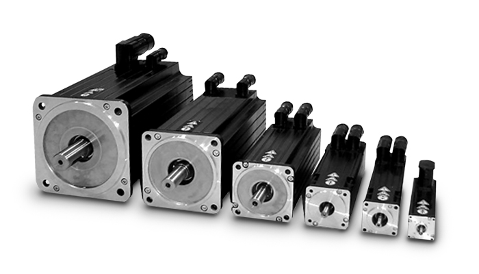
China ZD Electric Brushless DC Planetary Gear Motor For Solar Tracker Automatic Lawn Mower wholesaler
Solution Description
Design Assortment
ZD Leader has a vast range of micro motor creation strains in the industry, which includes DC Motor, AC Motor, Brushless Motor, Planetary Equipment Motor, Drum Motor, Planetary Gearbox, RV Reducer and Harmonic Gearbox and so on. Through technological innovation and customization, we support you generate outstanding application systems and provide adaptable remedies for different industrial automation situations.
• Design Variety
Our expert product sales representive and technical staff will pick the appropriate model and transmission options for your use rely on your specific parameters.
• Drawing Request
If you need much more item parameters, catalogues, CAD or 3D drawings, please contact us.
• On Your Want
We can modify regular merchandise or customize them to fulfill your specific demands.
Detailed Photos
Features:
The planetary gearbox for transmission is widely matched with DC motor and BLDC motor. It demonstrates the characters of large torque and controlablity as properly as the substantial long lasting torque. The ideal mix completely expresses the product’s scaled-down and substantial torque.
Other Connected Merchandise
Simply click below to locate what you are hunting for:
Company Profile
FAQ
Q: What’re your primary goods?
A: We presently create Brushed Dc Motors, Brushed Dc Gear Motors, Planetary Dc Equipment Motors, Brushless Dc Motors, Stepper motors, Ac Motors and Higher Precision Planetary Gear Box and so forth. You can check the technical specs for over motors on our website and you can e mail us to recommend essential motors for every your specification as well.
Q: How to choose a suitable motor?
A:If you have motor photographs or drawings to display us, or you have detailed specs like voltage, velocity, torque, motor measurement, working mode of the motor, necessary lifetime and sound degree and many others, please do not hesitate to let us know, then we can suggest ideal motor for each your ask for appropriately.
Q: Do you have a tailored services for your regular motors?
A: Sure, we can customize per your request for the voltage, velocity, torque and shaft dimensions/condition. If you need to have added wires/cables soldered on the terminal or need to add connectors, or capacitors or EMC we can make it way too.
Q: Do you have an individual layout services for motors?
A: Indeed, we would like to design and style motors separately for our consumers, but it may possibly require some mould building expense and design and style charge.
Q: What is your lead time?
A: Typically talking, our typical common solution will require fifteen-30days, a bit lengthier for tailored products. But we are really flexible on the lead time, it will depend on the certain orders.
|
US $20-100 / Piece | |
1 Piece (Min. Order) |
###
| Application: | Industrial, Power Tools, Car |
|---|---|
| Operating Speed: | Constant Speed |
| Number of Stator: | Single-Phase |
| Rotor Structure: | Squirrel-Cage |
| Casing Protection: | Closed Type |
| Number of Poles: | 2 |
###
| Customization: |
Available
|
|---|
|
US $20-100 / Piece | |
1 Piece (Min. Order) |
###
| Application: | Industrial, Power Tools, Car |
|---|---|
| Operating Speed: | Constant Speed |
| Number of Stator: | Single-Phase |
| Rotor Structure: | Squirrel-Cage |
| Casing Protection: | Closed Type |
| Number of Poles: | 2 |
###
| Customization: |
Available
|
|---|
Benefits of a Planetary Motor
Besides being one of the most efficient forms of a drive, a Planetary Motor also offers a great number of other benefits. These features enable it to create a vast range of gear reductions, as well as generate higher torques and torque density. Let’s take a closer look at the benefits this mechanism has to offer. To understand what makes it so appealing, we’ll explore the different types of planetary systems.
Solar gear
The solar gear on a planetary motor has two distinct advantages. It produces less noise and heat than a helical gear. Its compact footprint also minimizes noise. It can operate at high speeds without sacrificing efficiency. However, it must be maintained with constant care to operate efficiently. Solar gears can be easily damaged by water and other debris. Solar gears on planetary motors may need to be replaced over time.
A planetary gearbox is composed of a sun gear and two or more planetary ring and spur gears. The sun gear is the primary gear and is driven by the input shaft. The other two gears mesh with the sun gear and engage the stationary ring gear. The three gears are held together by a carrier, which sets the spacing. The output shaft then turns the planetary gears. This creates an output shaft that rotates.
Another advantage of planetary gears is that they can transfer higher torques while being compact. These advantages have led to the creation of solar gears. They can reduce the amount of energy consumed and produce more power. They also provide a longer service life. They are an excellent choice for solar-powered vehicles. But they must be installed by a certified solar energy company. And there are other advantages as well. When you install a solar gear on a planetary motor, the energy produced by the sun will be converted to useful energy.
A solar gear on a planetary motor uses a solar gear to transmit torque from the sun to the planet. This system works on the principle that the sun gear rotates at the same rate as the planet gears. The sun gear has a common design modulus of -Ns/Np. Hence, a 24-tooth sun gear equals a 3-1/2 planet gear ratio. When you consider the efficiency of solar gears on planetary motors, you will be able to determine whether the solar gears are more efficient.
Sun gear
The mechanical arrangement of a planetary motor comprises of two components: a ring gear and a sun gear. The ring gear is fixed to the motor’s output shaft, while the sun gear rolls around and orbits around it. The ring gear and sun gear are linked by a planetary carrier, and the torque they produce is distributed across their teeth. The planetary structure arrangement also reduces backlash, and is critical to achieve a quick start and stop cycle.
When the two planetary gears rotate independently, the sun gear will rotate counterclockwise and the ring-gear will turn in the same direction. The ring-gear assembly is mounted in a carrier. The carrier gear and sun gear are connected to each other by a shaft. The planetary gears and sun gear rotate around each other on the ring-gear carrier to reduce the speed of the output shaft. The planetary gear system can be multiplied or staged to obtain a higher reduction ratio.
A planetary gear motor mimics the planetary rotation system. The input shaft turns a central gear, known as the sun gear, while the planetary gears rotate around a stationary sun gear. The motor’s compact design allows it to be easily mounted to a vehicle, and its low weight makes it ideal for small vehicles. In addition to being highly efficient, a planetary gear motor also offers many other benefits.
A planetary gearbox uses a sun gear to provide torque to the other gears. The planet pinions mesh with an internal tooth ring gear to generate rotation. The carrier also acts as a hub between the input gear and output shaft. The output shaft combines these two components, giving a higher torque. There are three types of planetary gearboxes: the sun gear and a wheel drive planetary gearbox.
Planetary gear
A planetary motor gear works by distributing rotational force along a separating plate and a cylindrical shaft. A shock-absorbing device is included between the separating plate and cylindrical shaft. This depressed portion prevents abrasion wear and foreign particles from entering the device. The separating plate and shaft are positioned coaxially. In this arrangement, the input shaft and output shaft are rotated relative to one another. The rotatable disc absorbs the impact.
Another benefit of a planetary motor gear is its efficiency. Planetary motor gears are highly efficient at transferring power, with 97% of the input energy being transferred to the output. They can also have high gear ratios, and offer low noise and backlash. This design also allows the planetary gearbox to work with electric motors. In addition, planetary gears also have a long service life. The efficiency of planetary gears is due in part to the large number of teeth.
Other benefits of a planetary motor gear include the ease of changing ratios, as well as the reduced safety stock. Unlike other gears, planetary gears don’t require special tools for changing ratios. They are used in numerous industries, and share parts across multiple sizes. This means that they are cost-effective to produce and require less safety stock. They can withstand high shock and wear, and are also compact. If you’re looking for a planetary motor gear, you’ve come to the right place.
The axial end surface of a planetary gear can be worn down by abrasion with a separating plate. In addition, foreign particles may enter the planetary gear device. These particles can damage the gears or even cause noise. As a result, you should check planetary gears for damage and wear. If you’re looking for a gear, make sure it has been thoroughly tested and installed by a professional.
Planetary gearbox
A planetary motor and gearbox are a common combination of electric and mechanical power sources. They share the load of rotation between multiple gear teeth to increase the torque capacity. This design is also more rigid, with low backlash that can be as low as one or two arc minutes. The advantages of a planetary gearmotor over a conventional electric motor include compact size, high efficiency, and less risk of gear failure. Planetary gear motors are also more reliable and durable than conventional electric motors.
A planetary gearbox is designed for a single stage of reduction, or a multiple-stage unit can be built with several individual cartridges. Gear ratios may also be selected according to user preference, either to face mount the output stage or to use a 5mm hex shaft. For multi-stage planetary gearboxes, there are a variety of different options available. These include high-efficiency planetary gearboxes that achieve a 98% efficiency at single reduction. In addition, they are noiseless, and reduce heat loss.
A planetary gearbox may be used to increase torque in a robot or other automated system. There are different types of planetary gear sets available, including gearboxes with sliding or rolling sections. When choosing a planetary gearset, consider the environment and other factors such as backlash, torque, and ratio. There are many advantages to a planetary gearbox and the benefits and drawbacks associated with it.
Planetary gearboxes are similar to those in a solar system. They feature a central sun gear in the middle, two or more outer gears, and a ring gear at the output. The planetary gears rotate in a ring-like structure around a stationary sun gear. When the gears are engaged, they are connected by a carrier that is fixed to the machine’s shaft.
Planetary gear motor
Planetary gear motors reduce the rotational speed of an armature by one or more times. The reduction ratio depends on the structure of the planetary gear device. The planetary gear device has an output shaft and an armature shaft. A separating plate separates the two. The output shaft moves in a circular pattern to turn the pinion 3. When the pinion rotates to the engagement position, it is engaged with the ring gear 4. The ring gear then transmits the rotational torque to the armature shaft. The result is that the engine cranks up.
Planetary gear motors are cylindrical in shape and are available in various power levels. They are typically made of steel or brass and contain multiple gears that share the load. These motors can handle massive power transfers. The planetary gear drive, on the other hand, requires more components, such as a sun’s gear and multiple planetary gears. Consequently, it may not be suitable for all types of applications. Therefore, the planetary gear drive is generally used for more complex machines.
Brush dusts from the electric motor may enter the planetary gear device and cause it to malfunction. In addition, abrasion wear on the separating plate can affect the gear engagement of the planetary gear device. If this occurs, the gears will not engage properly and may make noise. In order to prevent such a situation from occurring, it is important to regularly inspect planetary gear motors and their abrasion-resistant separating plates.
Planetary gear motors come in many different power levels and sizes. These motors are usually cylindrical in shape and are made of steel, brass, plastic, or a combination of both materials. A planetary gear motor can be used in applications where space is an issue. This motor also allows for low gearings in small spaces. The planetary gearing allows for large amounts of power transfer. The output shaft size is dependent on the gear ratio and the motor speed.
editor by czh 2023-01-09
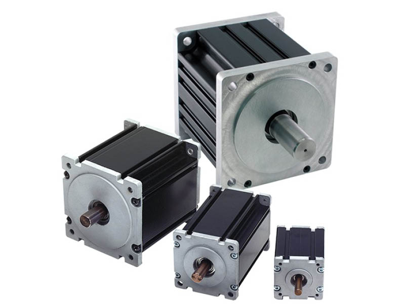
China ZD 62mm BLDC Brushless DC Planetary Geared Motor for Automatic Lawn Mower with Good quality
Merchandise Description
Design Choice
ZD Chief has a vast variety of micro motor manufacturing strains in the business, like DC Motor, AC Motor, Brushless Motor, Planetary Equipment Motor, Drum Motor, Planetary Gearbox, RV Reducer and Harmonic Gearbox and so on. By means of complex innovation and customization, we help you generate fantastic application programs and supply adaptable answers for numerous industrial automation circumstances.
• Product Selection
Our professional revenue representive and specialized staff will select the right model and transmission solutions for your usage rely on your specific parameters.
• Drawing Request
If you want a lot more solution parameters, catalogues, CAD or 3D drawings, please get in touch with us.
• On Your Need to have
We can modify normal products or customise them to meet your specific wants.
Thorough Pictures
Characteristics:
The planetary gearbox for transmission is widely matched with DC motor and BLDC motor. It exhibits the people of substantial torque and controlablity as effectively as the substantial lasting torque. The best mix completely expresses the product’s smaller and higher torque.
Other Relevant Products
Simply click right here to discover what you are searching for:
Organization Profile
FAQ
Q: What’re your primary goods?
A: We currently create Brushed Dc Motors, Brushed Dc Gear Motors, Planetary Dc Equipment Motors, Brushless Dc Motors, Stepper motors, Ac Motors and Large Precision Planetary Equipment Box and many others. You can examine the requirements for earlier mentioned motors on our internet site and you can electronic mail us to suggest necessary motors for every your specification also.
Q: How to select a ideal motor?
A:If you have motor photographs or drawings to demonstrate us, or you have comprehensive specs like voltage, velocity, torque, motor dimension, operating method of the motor, needed life time and sound stage etc, you should do not wait to let us know, then we can recommend appropriate motor per your ask for accordingly.
Q: Do you have a customized services for your common motors?
A: Yes, we can customize for each your ask for for the voltage, pace, torque and shaft measurement/condition. If you require further wires/cables soldered on the terminal or need to have to include connectors, or capacitors or EMC we can make it as well.
Q: Do you have an individual design and style services for motors?
A: Sure, we would like to layout motors separately for our clients, but it could require some mould establishing cost and layout demand.
Q: What’s your guide time?
A: Typically talking, our standard regular merchandise will require 15-30days, a bit more time for customized goods. But we are really adaptable on the lead time, it will depend on the particular orders.
|
US $20-100 / Piece | |
1 Piece (Min. Order) |
###
| Application: | Industrial, Power Tools, Car |
|---|---|
| Operating Speed: | Constant Speed |
| Number of Stator: | Single-Phase |
| Rotor Structure: | Squirrel-Cage |
| Casing Protection: | Closed Type |
| Number of Poles: | 2 |
###
| Customization: |
Available
|
|---|
|
US $20-100 / Piece | |
1 Piece (Min. Order) |
###
| Application: | Industrial, Power Tools, Car |
|---|---|
| Operating Speed: | Constant Speed |
| Number of Stator: | Single-Phase |
| Rotor Structure: | Squirrel-Cage |
| Casing Protection: | Closed Type |
| Number of Poles: | 2 |
###
| Customization: |
Available
|
|---|
Benefits of a Planetary Motor
A planetary motor has many benefits. Its compact design and low noise makes it a good choice for any application. Among its many uses, planetary gear motors are found in smart cars, consumer electronics, intelligent robots, communication equipment, and medical technology. They can even be found in smart homes! Read on to discover the benefits of a planetary gear motor. You’ll be amazed at how versatile and useful it is!
Self-centering planet gears ensure a symmetrical force distribution
A planetary motor is a machine with multiple, interlocking planetary gears. The output torque is inversely proportional to the diameters of the planets, and the transmission size has no bearing on the output torque. A torsional stress analysis of the retaining structure for this type of motor found a maximum shear stress of 64 MPa, which is equivalent to a safety factor of 3.1 for 6061 aluminum. Self-centering planet gears are designed to ensure a symmetrical force distribution throughout the transmission system, with the weakest component being the pinions.
A planetary gearbox consists of ring and sun gears. The pitch diameters of ring and planet gears are nearly equal. The number of teeth on these gears determines the average gear-ratio per output revolution. This error is related to the manufacturing precision of the gears. The effect of this error is a noise or vibration characteristic of the planetary gearbox.
Another design for a planetary gearbox is a traction-based variant. This design eliminates the need for timing marks and other restrictive assembly conditions. The design of the ring gear is similar to that of a pencil sharpener mechanism. The ring gear is stationary while planet gears extend into cylindrical cutters. When placed on the sun’s axis, the pencil sharpening mechanism revolves around the ring gear to sharpen the pencil.
The JDS eliminates the need for conventional planetary carriers and is mated with the self-centering planet gears by dual-function components. The dual-function components synchronize the rolling motion and traction of the gears. They also eliminate the need for a carrier and reduce the force distribution between the rotor and stator.
Metal gears
A planetary motor is a type of electric drive that uses a series of metal gears. These gears share a load attached to the output shaft to generate torque. The planetary motor is often CNC controlled, with extra-long shafts, which allow it to fit into very compact designs. These gears are available in sizes from seven millimeters to 12 millimeters. They can also be fitted with encoders.
Planetary gearing is widely used in various industrial applications, including automobile transmissions, off-road transmissions, and wheel drive motors. They are also used in bicycles to power the shift mechanism. Another use for planetary gearing is as a powertrain between an internal combustion engine and an electric motor. They are also used in forestry applications, such as debarking equipment and sawing. They can be used in other industries as well, such as pulp washers and asphalt mixers.
Planetary gear sets are composed of three types of gears: a sun gear, planet gears, and an outer ring. The sun gear transfers torque to the planet gears, and the planet gears mesh with the outer ring gear. Planet carriers are designed to deliver high-torque output at low speeds. These gears are mounted on carriers that are moved around the ring gear. The planet gears mesh with the ring gears, and the sun gear is mounted on a moveable carrier.
Plastic planetary gear motors are less expensive to produce than their metal counterparts. However, plastic gears suffer from reduced strength, rigidity, and load capacity. Metal gears are generally easier to manufacture and have less backlash. Plastic planetary gear motor bodies are also lighter and less noisy. Some of the largest plastic planetary gear motors are made in collaboration with leading suppliers. When buying a plastic planetary gear motor, be sure to consider what materials it is made of.
Encoder
The Mega Torque Planetary Encoder DC Geared Motor is designed with a Japanese Mabuchi motor RS-775WC, a 200 RPM base motor. It is capable of achieving stall torque at low speeds, which is impossible to achieve with a simple DC motor. The planetary encoder provides five pulses per revolution, making it perfect for applications requiring precise torque or position. This motor requires an 8mm hex coupling for proper use.
This encoder has a high resolution and is suitable for ZGX38REE, ZGX45RGG and ZGX50RHH. It features a magnetic disc and poles and an optical disc to feed back signals. It can count paulses as the motor passes through a hall on the circuit board. Depending on the gearbox ratio, the encoder can provide up to two million transitions per rotation.
The planetary gear motor uses a planetary gear system to distribute torque in synchrony. This minimizes the risk of gear failure and increases the overall output capacity of the device. On the other hand, a spur gear motor is a simpler design and cheaper to produce. The spur gear motor works better for lower torque applications as each gear bears all the load. As such, the torque capacity of the spur gear motor is lower than that of a planetary gear motor.
The REV UltraPlanetary gearbox is designed for FTC and has three different output shaft options. The output shaft is made of 3/8-inch hex, allowing for flexible shaft replacement. These motors are a great value as they can be used to meet a wide range of power requirements. The REV UltraPlanetary gearbox and motor are available for very reasonable prices and a female 5mm hex output shaft can be used.
Durability
One of the most common questions when selecting a planetary motor is “How durable is it?” This is a question that’s often asked by people. The good news is that planetary motors are extremely durable and can last for a long time if properly maintained. For more information, read on! This article will cover the durability and efficiency of planetary gearmotors and how you can choose the best one for your needs.
First and foremost, planetary gear sets are made from metal materials. This increases their lifespan. The planetary gear set is typically made of metals such as nickel-steel and steel. Some planetary gear motors use plastic. Steel-cut gears are the most durable and suitable for applications that require more torque. Nickel-steel gears are less durable, but are better able to hold lubricant.
Durability of planetary motor gearbox is important for applications requiring high torque versus speed. VEX VersaPlanetary gearboxes are designed for FRC(r) use and are incredibly durable. They are expensive, but they are highly customizable. The planetary gearbox can be removed for maintenance and replacement if necessary. Parts for the gearbox can be purchased separately. VEX VersaPlanetary gearboxes also feature a pinion clamped onto the motor shaft.
Dynamic modeling of the planetary gear transmission system is important for understanding its durability. In previous studies, uncoupled and coupled meshing models were used to investigate the effect of various design parameters on the vibration characteristics of the planetary gear system. This analysis requires considering the role of the mesh stiffness, structure stiffness, and moment of inertia. Moreover, dynamic models for planetary gear transmission require modeling the influence of multiple parameters, such as mesh stiffness and shaft location.
Cost
The planetary gear motor has multiple contact points that help the rotor rotate at different speeds and torques. This design is often used in stirrers and large vats of liquid. This type of motor has a low initial cost and is more commonly found in low-torque applications. A planetary gear motor has multiple contact points and is more effective for applications requiring high torque. Gear motors are often found in stirring mechanisms and conveyor belts.
A planetary gearmotor is typically made from four mechanically linked rotors. They can be used for various applications, including automotive and laboratory automation. The plastic input stage gears reduce noise at higher speeds. Steel gears can be used for high torques and a modified lubricant is often added to reduce weight and mass moment of inertia. Its low-cost design makes it an excellent choice for robots and other applications.
There are many different types of planetary gear motors available. A planetary gear motor has three gears, the sun gear and planet gears, with each sharing equal amounts of work. They are ideal for applications requiring high torque and low-resistance operation, but they require more parts than their single-stage counterparts. The steel cut gears are the most durable, and are often used in applications that require high speeds. The nickel-steel gears are more absorptive, which makes them better for holding lubricant.
A planetary gear motor is a high-performance electrical vehicle motor. A typical planetary gear motor has a 3000 rpm speed, a peak torque of 0.32 Nm, and is available in 24V, 36V, and 48V power supply. It is also quiet and efficient, requiring little maintenance and offering greater torque to a modern electric car. If you are thinking of buying a planetary gear motor, be sure to do a bit of research before purchasing one.
editor by czh 2022-12-13