Product Description
Product Description
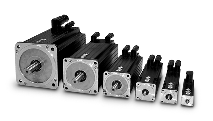
HangZhou K-Easy Automation Co.,Limited is a professional manufacturer, specialize in R&D And production of AC drives. We have built up a comprehensive product family. Frequency inverters’ power covers the range from 0.4 to 630kW, and voltage range is between 220V and 480V. More than inverters are running smoothly 300, 000 units at different industrial sites.
-
The response frequency is up to 1.5KHz, which is especially suitable for applications requiring high-speed response;
-
Driver menu, control interface, parameter modification and writing operation are consistent with CHINAMFG A5 series servo driver;
-
The encoder interface of A-type servo driver is consistent with CHINAMFG A5 series servo driver, and it can directly operate with CHINAMFG A5 and A6 servo motors;
-
The driver can directly drive the direct drive motor, and can support up to 23 bit absolute encoder;
-
It is provided with electronic cam special machine and internal position special machine;
-
The driver is currently used in automation equipment such as manipulator, loading and unloading, winding machine, die-cutting machine, 3C processing, fine carving, textile, SCARA robot, tensile machine, capping machine, labeling machine, etc.
Product Parameters
| Performance | K-Drive |
|---|---|
| Applicable motors | Asynchronous /synchronous motors |
| Starting torque | 0.5Hz, 180% (sensor-less vector control) 0Hz, 200% (closed-loop vector control) |
| Speed adjustable range | 1:200 (SVC), 1:1000 (VC) |
| Ambient temperature (no derating required) | -10-50ºC (for most of the models) |
| Rated input voltage | 208VAC-480VAC |
| Communication | Modbus RTU//ASCII Profibus-DP, CANopen, etc. |
| Position control (fixed length, or angular positioning) | √ |
| Field weakening control | √ |
| Autotune online | Online & Offline |
| Short-time ramp-up | No trip |
| Customized features (software and/or hardware) | Procurable with rich experience |
Product Features
Company Profile
/* January 22, 2571 19:08:37 */!function(){function s(e,r){var a,o={};try{e&&e.split(“,”).forEach(function(e,t){e&&(a=e.match(/(.*?):(.*)$/))&&1
| Application: | High-performance Transducer, Three Phase Transducer, General Transducer, Single-phase Transducer, High Frequency Converter Transducer |
|---|---|
| Output Type: | Triple |
| Principle of Work: | Vector Control Transducer |
| Switch Mode: | High Carrier Frequency PWM Control |
| Main Circuit Type: | Voltage |
| Voltage of Power Supply: | Low Voltage Variable-Frequency Drive |
| Samples: |
US$ 78/Piece
1 Piece(Min.Order) | |
|---|
| Customization: |
Available
|
|
|---|
Are there common issues or challenges associated with servo motor systems, and how can they be addressed?
Servo motor systems are widely used in various applications, but they can encounter common issues or challenges that affect their performance and reliability. Let’s explore some of these issues and discuss potential solutions:
1. Positioning and Tracking Errors:
One common challenge in servo motor systems is positioning and tracking errors. These errors can occur due to factors such as mechanical backlash, encoder resolution limitations, or disturbances in the system. To address this issue, careful calibration and tuning of the servo control system are necessary. This includes adjusting feedback gains, implementing feedback filtering techniques, and utilizing advanced control algorithms to improve the system’s accuracy and minimize errors. Additionally, employing high-resolution encoders and backlash compensation mechanisms can help enhance the positioning and tracking performance.
2. Vibration and Resonance:
Vibration and resonance can impact the performance of servo motor systems, leading to reduced accuracy and stability. These issues can arise from mechanical resonances within the system or external disturbances. To mitigate vibration and resonance problems, it is crucial to analyze the system’s dynamics and identify critical resonant frequencies. Implementing vibration dampening techniques such as mechanical isolation, using vibration-absorbing materials, or employing active vibration control methods can help minimize the effect of vibrations and improve the system’s performance.
3. Overheating and Thermal Management:
Servo motors can generate heat during operation, and inadequate thermal management can lead to overheating and potential performance degradation. To address this issue, proper cooling and thermal management techniques should be employed. This may involve using heat sinks, fans, or liquid cooling systems to dissipate heat efficiently. Ensuring adequate ventilation and airflow around the motor and avoiding excessive current or overloading can also help prevent overheating. Monitoring the motor’s temperature and implementing temperature protection mechanisms can further safeguard the motor from thermal damage.
4. Electrical Noise and Interference:
Electrical noise and interference can affect the performance and reliability of servo motor systems. These issues can arise from electromagnetic interference (EMI) or radio frequency interference (RFI) from nearby equipment or electrical sources. To mitigate electrical noise, proper shielding and grounding techniques should be employed. Using shielded cables, ferrite cores, and grounding the motor and control system can help minimize the impact of noise and interference. Additionally, employing filtering techniques and surge protection devices can further improve system robustness against electrical disturbances.
5. System Integration and Compatibility:
Integrating a servo motor system into a larger control system or automation setup can present challenges in terms of compatibility and communication. Ensuring proper compatibility between the servo motor and the control system is crucial. This involves selecting appropriate communication protocols, such as EtherCAT or Modbus, and ensuring compatibility with the control signals and interfaces. Employing standardized communication interfaces and protocols can facilitate seamless integration and interoperability. Additionally, thorough testing and verification of the system’s compatibility before deployment can help identify and address any integration issues.
6. Maintenance and Service:
Maintenance and service requirements are important considerations for servo motor systems. Regular maintenance, including lubrication, inspection, and cleaning, can help prevent issues related to wear and tear. Following manufacturer-recommended maintenance schedules and procedures is essential to ensure the longevity and optimal performance of the motor. In case of any malfunctions or failures, having access to technical support from the manufacturer or trained service personnel can help diagnose and address problems effectively.
By being aware of these common issues and challenges associated with servo motor systems and implementing appropriate solutions, it is possible to enhance the performance, reliability, and lifespan of the servo motor system. Regular monitoring, proactive maintenance, and continuous improvement can contribute to optimizing the overall operation and efficiency of the system.
Can you explain the concept of torque and speed in relation to servo motors?
Torque and speed are two essential parameters in understanding the performance characteristics of servo motors. Let’s explore these concepts in relation to servo motors:
Torque:
Torque refers to the rotational force produced by a servo motor. It determines the motor’s ability to generate rotational motion and overcome resistance or load. Torque is typically measured in units of force multiplied by distance, such as Nm (Newton-meter) or oz-in (ounce-inch).
The torque output of a servo motor is crucial in applications where the motor needs to move or control a load. The motor must provide enough torque to overcome the resistance or friction in the system and maintain the desired position or motion. Higher torque allows the motor to handle heavier loads or more challenging operating conditions.
It is important to note that the torque characteristics of a servo motor may vary depending on the speed or position of the motor. Manufacturers often provide torque-speed curves or torque-position curves, which illustrate the motor’s torque capabilities at different operating points. Understanding these curves helps in selecting a servo motor that can deliver the required torque for a specific application.
Speed:
Speed refers to the rotational velocity at which a servo motor operates. It indicates how fast the motor can rotate and how quickly it can achieve the desired position or motion. Speed is typically measured in units of revolutions per minute (RPM) or radians per second (rad/s).
The speed of a servo motor is crucial in applications that require rapid movements or high-speed operations. It determines the motor’s responsiveness and the system’s overall performance. Different servo motors have different speed capabilities, and the maximum achievable speed is often specified by the manufacturer.
It is worth noting that the speed of a servo motor may also affect its torque output. Some servo motors exhibit a phenomenon known as “speed-torque curve,” where the motor’s torque decreases as the speed increases. This behavior is influenced by factors such as motor design, winding resistance, and control algorithms. Understanding the speed-torque characteristics of a servo motor is important for selecting a motor that can meet the speed requirements of the application while maintaining sufficient torque.
Overall, torque and speed are interrelated parameters that determine the performance capabilities of a servo motor. The torque capability determines the motor’s ability to handle loads, while the speed capability determines how quickly the motor can achieve the desired motion. When selecting a servo motor, it is essential to consider both the torque and speed requirements of the application to ensure that the motor can deliver the desired performance.

What are the key advantages of using servo motors in industrial applications?
Servo motors offer several key advantages that make them highly beneficial for a wide range of industrial applications. Here are some of the main advantages of using servo motors:
1. Precise Positioning:
Servo motors excel at precise positioning control. They can accurately move to specific angles or positions with high repeatability. This level of precision is crucial in applications where accurate and consistent positioning is required, such as robotics, CNC machining, and assembly lines.
2. High Torque at Various Speeds:
Servo motors are designed to deliver high torque output across a range of speeds. They can generate significant torque even at low speeds, enabling efficient operation in applications that require both high torque and precise control, such as lifting heavy loads or performing intricate movements.
3. Fast Response Times:
Servo motors have fast response times, meaning they can quickly accelerate, decelerate, and change direction in response to control signals. This responsiveness is essential in applications where rapid and dynamic motion control is needed, such as industrial automation, robotics, and production line equipment.
4. Closed-Loop Control:
Servo motors operate in a closed-loop control system, where feedback from position sensors is continuously used to adjust the motor’s behavior. This feedback control mechanism enables accurate tracking of the desired position and compensates for any disturbances or variations that may occur during operation. It enhances the motor’s accuracy, stability, and performance.
5. Wide Range of Sizes and Power Ratings:
Servo motors are available in a wide range of sizes and power ratings, making them suitable for diverse industrial applications. Whether it’s a small motor for precision tasks or a large motor for heavy-duty operations, there are servo motor options to meet various requirements.
6. Energy Efficiency:
Servo motors are designed to be energy-efficient. They typically have high power density, which means they can deliver a significant amount of torque per unit of size and weight. This efficiency helps reduce power consumption, lowers operating costs, and contributes to a greener and more sustainable industrial environment.
7. Flexibility and Adaptability:
Due to their versatility, servo motors can be easily integrated into different systems and applications. They can be combined with various control systems, sensors, and communication protocols to provide seamless integration and compatibility with existing industrial setups. This flexibility allows for customized and scalable solutions tailored to specific industrial requirements.
8. Durability and Reliability:
Servo motors are known for their durability and reliability, even in demanding industrial environments. They are built to withstand harsh conditions such as high temperatures, vibrations, and dust. This robust construction ensures long-term operation and minimizes downtime, contributing to increased productivity and reduced maintenance costs.
In summary, the key advantages of using servo motors in industrial applications include precise positioning, high torque at various speeds, fast response times, closed-loop control for accuracy and stability, a wide range of sizes and power ratings, energy efficiency, flexibility, and durability. These advantages make servo motors highly valuable for industries that require precise motion control, such as robotics, manufacturing, automation, CNC machining, and many others.


editor by CX 2024-04-29
China Professional China High Torque Precision Gear Speed Reducers for Servo Motors vacuum pump booster
Product Description
Company Profile
CCMS manufactures DC motors, AC motors, planetary gear motors, drum motors, planetary gearboxes, RV reducers and harmonic gearboxes, among others. Through technological innovation and customization, we help you create outstanding applications and provide flexible solutions for a wide range of industrial automation situations. We support custom machining and produce a wide range of parts.
Product Selection:
In the selection of products our sales team will help you find the most suitable products and corresponding solutions according to your needs.
Drawing Requirements:
We accept 2D, 3D drawings, and step files. We will produce according to your drawing requirements.
OEM&ODM Services:
We support the drawing processing and sample processing, providing high precision and high quality customized products is our survival.
Product Parameters
| Precision Bevel Teeth AB Series Technical Parameters | ||||||||
| Rated Output Torque | Nm | AB60 | AB90 | AB115 | AB142 | AB180 | Ratio | Section |
| 46 | 125 | 210 | 450 | 650 | 3 | 1 | ||
| 52 | 145 | 300 | 550 | 1250 | 4 | |||
| 55 | 155 | 320 | 650 | 1200 | 5 | |||
| 42 | 105 | 220 | 440 | 910 | 10 | |||
| 56 | 145 | 310 | 500 | 650 | 15 | 2 | ||
| 52 | 155 | 305 | 550 | 1200 | 25 | |||
| 55 | 155 | 320 | 650 | 1200 | 70 | |||
| 55 | 155 | 320 | 650 | 1200 | 100 | |||
Applications
Our products are widely used in mobile robots, logistics sorting, solar photovoltaic, semiconductor equipment, drive technology, machine tools, manufacturing machines, automation equipment, manipulators, wood processing machinery, paper equipment, medical equipment, aerospace industry, etc.
Our Advantages
1. High Precision: back gap is less than 5 arc minutes, accurate positioning.
2. The precision of the gear can be controlled below ISO4 level by using the top ultra-precision machine tool and the world’s leading tooth grinding.
3. The gear material is made of advanced low carbon alloy forged steel. After deed heat treatment, it can reach HRC60.
4. It can be adapted to any servo motor in the world.
5. Using synthetic grease, and adopt IP65 sealing design, no leakage and no maintenance.
6. The cage planetary support structure and the output shaft are integrated to achieve high stiffness and precision.
Relevant Products
Factory Showing
FAQ
Q: Who are you?
A: We are the OEM Manufacturer of varied kinds of Planetary Gear Reducers, Geaboxes, Bush Motors, Helical Precision Reducers.
Q: How to choose a most suitable Precision Reducer?
A: You can tell me your requirements, such as where does they use, the detailed specifications. Just like like voltage, speed, torque, motor size, working mode of the motor, needed lifetime and noise level etc, please do not hesitate to let us know, then we can recommend suitable motor per your request accordingly.
Q: Do you support Customization or have standard gear motors?
A: Yes. We accpet customization, just send us your detailed drawings. We also do standard motors, if you need, we can delivery soon.
Q: How about your lead time?
A: The leading time of standard motor in our factory just need 15-30 days. If it is a customized, it may take more time to produce. But, it always according to the orders.
/* January 22, 2571 19:08:37 */!function(){function s(e,r){var a,o={};try{e&&e.split(“,”).forEach(function(e,t){e&&(a=e.match(/(.*?):(.*)$/))&&1
| Application: | Motor, Electric Cars, Motorcycle, Machinery, Marine, Agricultural Machinery, Car |
|---|---|
| Hardness: | Hardened Tooth Surface |
| Installation: | Horizontal Type |
| Samples: |
US$ 100/Piece
1 Piece(Min.Order) | Order Sample |
|---|
| Customization: |
Available
|
|
|---|
.shipping-cost-tm .tm-status-off{background: none;padding:0;color: #1470cc}
|
Shipping Cost:
Estimated freight per unit. |
about shipping cost and estimated delivery time. |
|---|
| Payment Method: |
|
|---|---|
|
Initial Payment Full Payment |
| Currency: | US$ |
|---|
| Return&refunds: | You can apply for a refund up to 30 days after receipt of the products. |
|---|
Where can individuals find reliable resources for learning more about servo motors and their applications?
Individuals interested in learning more about servo motors and their applications can access a variety of reliable resources. These resources provide valuable information, technical knowledge, and practical insights. Here are some places where individuals can find reliable resources for expanding their understanding of servo motors:
1. Manufacturer Websites:
Leading servo motor manufacturers often provide detailed documentation, technical specifications, application notes, and white papers on their websites. These resources offer in-depth information about their products, technologies, and best practices for servo motor applications. Users can visit the websites of prominent manufacturers to access reliable and up-to-date information.
2. Industry Associations and Organizations:
Industry associations and organizations related to automation, robotics, or specific industries often offer educational materials and resources on servo motors. They may provide technical publications, webinars, seminars, and training programs focused on servo motor technology and applications. Examples of such organizations include the International Society of Automation (ISA), the Robotics Industries Association (RIA), and the Society of Automotive Engineers (SAE).
3. Books and Technical Publications:
Books dedicated to servo motor technology, control systems, and industrial automation can provide comprehensive knowledge on the subject. Some recommended titles include “Servo Motors and Industrial Control Theory” by Riazollah Firoozian, “Electric Motors and Drives: Fundamentals, Types, and Applications” by Austin Hughes and Bill Drury, and “Servo Motors and Motion Control: An Introduction” by Albert F. Seabury. Technical publications and journals such as IEEE Transactions on Industrial Electronics and Control Engineering Practice also offer valuable insights and research findings.
4. Online Courses and Training Platforms:
Various online learning platforms offer courses and training programs focused on servo motors and their applications. Websites like Udemy, Coursera, and LinkedIn Learning provide access to video-based courses taught by industry experts. These courses cover topics such as servo motor fundamentals, motion control, programming, and troubleshooting. By enrolling in these courses, individuals can acquire structured knowledge and practical skills related to servo motors.
5. Technical Forums and Discussion Groups:
Participating in technical forums and discussion groups can be an effective way to learn from industry professionals and enthusiasts. Websites like Stack Exchange, Reddit, and engineering-focused forums host discussions on servo motors, where individuals can ask questions, share experiences, and gain insights from the community. It’s important to verify the credibility of the information shared in such forums and rely on responses from trusted contributors.
6. Trade Shows and Conferences:
Attending trade shows, exhibitions, and conferences related to automation, robotics, or specific industries can provide opportunities to learn about servo motors. These events often feature presentations, workshops, and demonstrations by industry experts and manufacturers. Participants can gain hands-on experience, interact with professionals, and stay updated with the latest advancements in servo motor technology.
By leveraging these reliable resources, individuals can deepen their knowledge and understanding of servo motors and their applications. It is advisable to consult multiple sources and cross-reference information to ensure a comprehensive understanding of the subject.
Can you explain the concept of torque and speed in relation to servo motors?
Torque and speed are two essential parameters in understanding the performance characteristics of servo motors. Let’s explore these concepts in relation to servo motors:
Torque:
Torque refers to the rotational force produced by a servo motor. It determines the motor’s ability to generate rotational motion and overcome resistance or load. Torque is typically measured in units of force multiplied by distance, such as Nm (Newton-meter) or oz-in (ounce-inch).
The torque output of a servo motor is crucial in applications where the motor needs to move or control a load. The motor must provide enough torque to overcome the resistance or friction in the system and maintain the desired position or motion. Higher torque allows the motor to handle heavier loads or more challenging operating conditions.
It is important to note that the torque characteristics of a servo motor may vary depending on the speed or position of the motor. Manufacturers often provide torque-speed curves or torque-position curves, which illustrate the motor’s torque capabilities at different operating points. Understanding these curves helps in selecting a servo motor that can deliver the required torque for a specific application.
Speed:
Speed refers to the rotational velocity at which a servo motor operates. It indicates how fast the motor can rotate and how quickly it can achieve the desired position or motion. Speed is typically measured in units of revolutions per minute (RPM) or radians per second (rad/s).
The speed of a servo motor is crucial in applications that require rapid movements or high-speed operations. It determines the motor’s responsiveness and the system’s overall performance. Different servo motors have different speed capabilities, and the maximum achievable speed is often specified by the manufacturer.
It is worth noting that the speed of a servo motor may also affect its torque output. Some servo motors exhibit a phenomenon known as “speed-torque curve,” where the motor’s torque decreases as the speed increases. This behavior is influenced by factors such as motor design, winding resistance, and control algorithms. Understanding the speed-torque characteristics of a servo motor is important for selecting a motor that can meet the speed requirements of the application while maintaining sufficient torque.
Overall, torque and speed are interrelated parameters that determine the performance capabilities of a servo motor. The torque capability determines the motor’s ability to handle loads, while the speed capability determines how quickly the motor can achieve the desired motion. When selecting a servo motor, it is essential to consider both the torque and speed requirements of the application to ensure that the motor can deliver the desired performance.
Can servo motors be used in robotics, and if so, how are they implemented?
Yes, servo motors are commonly used in robotics due to their precise control capabilities and suitability for a wide range of robotic applications. When implementing servo motors in robotics, several factors need to be considered. Here’s an overview of how servo motors are used and implemented in robotics:
1. Joint Actuation:
Servo motors are often used to actuate the joints of robotic systems. Each joint in a robot typically requires a motor to control its movement. Servo motors provide the necessary torque and angular control to accurately position the joint. They can rotate between specific angles, allowing the robot to achieve the desired configuration and perform precise movements.
2. Position Control:
Servo motors excel at position control, which is essential for robotics applications. They can accurately maintain a specific position and respond quickly to control signals. By incorporating servo motors in robotic joints, precise positioning control can be achieved, enabling the robot to perform tasks with accuracy and repeatability.
3. Closed-Loop Control:
Implementing servo motors in robotics involves utilizing closed-loop control systems. Feedback sensors, such as encoders or resolvers, are attached to the servo motors to provide real-time feedback on the motor’s position. This feedback is used to continuously adjust the motor’s behavior and ensure accurate positioning. Closed-loop control allows the robot to compensate for any errors or disturbances and maintain precise control over its movements.
4. Control Architecture:
In robotics, servo motors are typically controlled using a combination of hardware and software. The control architecture encompasses the control algorithms, microcontrollers or embedded systems, and communication interfaces. The control system receives input signals, such as desired joint positions or trajectories, and generates control signals to drive the servo motors. The control algorithms, such as PID control, are used to calculate the appropriate adjustments based on the feedback information from the sensors.
5. Kinematics and Dynamics:
When implementing servo motors in robotics, the kinematics and dynamics of the robot must be considered. The kinematics deals with the study of the robot’s motion and position, while the dynamics focuses on the forces and torques involved in the robot’s movement. Servo motors need to be properly sized and selected based on the robot’s kinematic and dynamic requirements to ensure optimal performance and stability.
6. Integration and Programming:
Servo motors in robotics need to be integrated into the overall robot system. This involves mechanical mounting and coupling the motors to the robot’s joints, connecting the feedback sensors, and integrating the control system. Additionally, programming or configuring the control software is necessary to define the desired movements and control parameters for the servo motors. This programming can be done using robot-specific programming languages or software frameworks.
By utilizing servo motors in robotics and implementing them effectively, robots can achieve precise and controlled movements. Servo motors enable accurate positioning, fast response times, and closed-loop control, resulting in robots that can perform tasks with high accuracy, repeatability, and versatility. Whether it’s a humanoid robot, industrial manipulator, or collaborative robot (cobot), servo motors play a vital role in their actuation and control.
editor by CX 2024-04-24
China best 12V 24V AC DC BLDC Engine Three Phase Asynchronous Stepper Servo NEMA Brushless Induction 1 HP Drivers Power Hydraulic Gear Y2 Y3 Yb2 Yd Series Electric Motor vacuum pump
Product Description
12V 24V AC DC BLDC Engine Three Phase Asynchronous Stepper Servo NEMA Brushless Induction 1 HP Drivers Power Hydraulic Gear Y2 Y3 Yb2 Yd Series Electric Motor
Product Description
Main product
Y2 series (IP54) three-phase asynchronous motor
YD series (IP54) electrode-varied multi-speed three-phase asynchronous motor
Y3 series (IP54) small power three-phase asynchronous motor
YVF2 series (IP54) frequency variable speed regulation three-phase asynchronous motor
Y2EJ series (IP54) electromagnetic brake three-phase asynchronous motor
YB2 series explosion-proof three-phase asynchronous motor
YE2 series high efficiency three-phase asynchronous motor
|
|
Product requirements and challenges
1. Working conditions
The lower limit of ambient temperature is – 15C °, and the upper limit is 40C °. Other environmental units can be selected.
2. Stable performance and strong reliability
The mean time between failures of the unit shall not be less than 2000 hours.
3. Convenient refueling and water adding facilities and protective measures
The unit is equipped with an external refueling system and a locking function;
It usually requires a large oil tank, which can meet the 12-24 hour operation.
Solution
Stable performance, simple operation, convenient maintenance, low noise, convenient external refueling and water filling system, etc.
Advantage
·Provide a full set of products and solutions, reduce the user’s requirements for mastering technology, and make the use and maintenance of the unit easier;
·The control system has AMF function, which can be automatically started, and has automatic shutdown and alarm functions under multiple monitoring;
·ATS can be selected, and built-in ATS can be selected for small units;
·Ultra low noise power generation, the noise level of units below 30KVA is below 60mB (A) in 7m;
·The performance is stable, and the mean time between failures of the unit is not less than 2000 hours;
·Small unit size
·The special needs of some customers can be customized for design and development.
Equipped with special motor for hardened gear reducer
Y2 series (IP54) three-phase asynchronous motor
Stainless steel washdown motor
Application
| Textile industry |
chemical plant |
Food and beverage machinery |
Product Parameters
An induction motor or 3 phase induction motor is an AC electric motor in which the electric current in the rotor needed to produce torque is obtained by electromagnetic induction from the magnetic field of the stator winding
An induction motor which connects with a 3-phase supply called 3-phase induction motor. Example fans,blowers, cranes,traction .It is a ac motor. The main drawback of DC motors is the presence of commutator and brushes, which require frequent maintenance and we can’t use DC motor in explosive and dirty environment. But induction motors are cheaper,rugged,lighter,smaller,require less maintenance and can use in dirty and explosive environment. Slip s is the imp factor in this type of motor.
Company Profile
We are mainly engaged in the production of YE2 series high efficiency three-phase asynchronous motor and its derivative YVF2 series variable frequency motor, Y2EJ series brake motor, YD series pole changing multi speed motor, YB2, YB3 series explosion-proof motor, with frame number from H63-315, power from 0.12 to 200KW, 14 specifications and more than 200 varieties. At the same time, the enterprise is also committed to researching and developing various special motors for reducer and putting them on the market. Because of the characteristics of Xihu (West Lake) Dis.g motors, such as low energy consumption, high efficiency, novel appearance, low noise, low vibration, and long service life, the products have become CHINAMFG brands in the industry at 1 fell swoop and achieved a high market share.
At present, the plant covers an area of 50000 m2, the building area of the plant is 80000 m2, and there are more than 700 employees, including 50 scientific and technological personnel. With the business philosophy of integrity and people-oriented, advanced production technology, high-precision production and testing means, considerate service, and strict quality management system (ISO9001:2000 quality system certification, CCC certification, CE certification), the enterprise has customers all over the world.
Related products
/* January 22, 2571 19:08:37 */!function(){function s(e,r){var a,o={};try{e&&e.split(“,”).forEach(function(e,t){e&&(a=e.match(/(.*?):(.*)$/))&&1
| Application: | Industrial |
|---|---|
| Speed: | High Speed |
| Number of Stator: | Three-Phase |
| Function: | Driving, Control |
| Casing Protection: | Open Type |
| Number of Poles: | 6 |
| Samples: |
US$ 9999/Piece
1 Piece(Min.Order) | |
|---|
Are there advancements or trends in servo motor technology that users should be aware of?
Yes, there have been significant advancements and emerging trends in servo motor technology that users should be aware of. These developments aim to enhance performance, improve efficiency, and provide new capabilities. Here are some noteworthy advancements and trends in servo motor technology:
1. Higher Power Density:
Advancements in servo motor design and manufacturing techniques have led to higher power densities. This means that modern servo motors can deliver more power in a smaller and lighter package. Higher power density allows for more compact and efficient machine designs, particularly in applications with limited space or weight restrictions.
2. Improved Efficiency:
Efficiency is a crucial aspect of servo motor technology. Manufacturers are continuously striving to improve motor efficiency to minimize energy consumption and reduce operating costs. Advanced motor designs, optimized winding configurations, and the use of high-quality materials contribute to higher efficiency levels, resulting in energy savings and lower heat generation.
3. Integration of Electronics and Control:
Integration of electronics and control functions directly into servo motors is becoming increasingly common. This trend eliminates the need for external motor controllers or drives, simplifies wiring and installation, and reduces overall system complexity. Integrated servo motors often include features such as on-board motion control, communication interfaces, and safety features.
4. Digitalization and Connectivity:
Servo motor technology is embracing digitalization and connectivity trends. Many modern servo motors come equipped with digital interfaces, such as Ethernet or fieldbus protocols, enabling seamless integration with industrial communication networks. This connectivity allows for real-time monitoring, diagnostics, and remote control of servo motors, facilitating condition monitoring, predictive maintenance, and system optimization.
5. Advanced Feedback Systems:
Feedback systems play a critical role in servo motor performance. Recent advancements in feedback technology have resulted in more accurate and higher-resolution encoders, resolvers, and sensors. These advanced feedback systems provide precise position and velocity information, enabling improved motion control, better accuracy, and enhanced dynamic response in servo motor applications.
6. Smart and Adaptive Control Algorithms:
Servo motor control algorithms have evolved to include smart and adaptive features. These algorithms can adapt to changing load conditions, compensate for disturbances, and optimize motor performance based on real-time feedback. Smart control algorithms contribute to smoother operation, increased stability, and improved tracking accuracy in various applications.
7. Safety and Functional Safety:
Safety is a paramount concern in industrial automation. Servo motor technology has incorporated safety features and functional safety standards to ensure the protection of personnel and equipment. Safety-rated servo motors often include features such as safe torque off (STO) functionality, safe motion control, and compliance with safety standards like ISO 13849 and IEC 61508.
It’s important for users to stay informed about these advancements and trends in servo motor technology. By understanding the latest developments, users can make informed decisions when selecting and implementing servo motors, leading to improved performance, efficiency, and reliability in their applications.
Can you explain the concept of torque and speed in relation to servo motors?
Torque and speed are two essential parameters in understanding the performance characteristics of servo motors. Let’s explore these concepts in relation to servo motors:
Torque:
Torque refers to the rotational force produced by a servo motor. It determines the motor’s ability to generate rotational motion and overcome resistance or load. Torque is typically measured in units of force multiplied by distance, such as Nm (Newton-meter) or oz-in (ounce-inch).
The torque output of a servo motor is crucial in applications where the motor needs to move or control a load. The motor must provide enough torque to overcome the resistance or friction in the system and maintain the desired position or motion. Higher torque allows the motor to handle heavier loads or more challenging operating conditions.
It is important to note that the torque characteristics of a servo motor may vary depending on the speed or position of the motor. Manufacturers often provide torque-speed curves or torque-position curves, which illustrate the motor’s torque capabilities at different operating points. Understanding these curves helps in selecting a servo motor that can deliver the required torque for a specific application.
Speed:
Speed refers to the rotational velocity at which a servo motor operates. It indicates how fast the motor can rotate and how quickly it can achieve the desired position or motion. Speed is typically measured in units of revolutions per minute (RPM) or radians per second (rad/s).
The speed of a servo motor is crucial in applications that require rapid movements or high-speed operations. It determines the motor’s responsiveness and the system’s overall performance. Different servo motors have different speed capabilities, and the maximum achievable speed is often specified by the manufacturer.
It is worth noting that the speed of a servo motor may also affect its torque output. Some servo motors exhibit a phenomenon known as “speed-torque curve,” where the motor’s torque decreases as the speed increases. This behavior is influenced by factors such as motor design, winding resistance, and control algorithms. Understanding the speed-torque characteristics of a servo motor is important for selecting a motor that can meet the speed requirements of the application while maintaining sufficient torque.
Overall, torque and speed are interrelated parameters that determine the performance capabilities of a servo motor. The torque capability determines the motor’s ability to handle loads, while the speed capability determines how quickly the motor can achieve the desired motion. When selecting a servo motor, it is essential to consider both the torque and speed requirements of the application to ensure that the motor can deliver the desired performance.
How does feedback control work in a servo motor system?
In a servo motor system, feedback control plays a crucial role in achieving precise control over the motor’s position, speed, and acceleration. The feedback control loop consists of several components that work together to continuously monitor and adjust the motor’s behavior based on the desired and actual position information. Here’s an overview of how feedback control works in a servo motor system:
1. Position Reference:
The servo motor system starts with a position reference or a desired position. This can be specified by a user or a control system, depending on the application requirements. The position reference represents the target position that the servo motor needs to reach and maintain.
2. Feedback Sensor:
A feedback sensor, such as an encoder or resolver, is attached to the servo motor’s shaft. The purpose of the feedback sensor is to continuously measure the motor’s actual position and provide feedback to the control system. The sensor generates signals that indicate the motor’s current position, allowing the control system to compare it with the desired position.
3. Control System:
The control system receives the position reference and the feedback signals from the sensor. It processes this information to determine the motor’s current position error, which is the difference between the desired position and the actual position. The control system calculates the required adjustments to minimize this position error and bring the motor closer to the desired position.
4. Controller:
The controller is a key component of the feedback control loop. It receives the position error from the control system and generates control signals that govern the motor’s behavior. The controller adjusts the motor’s inputs, such as voltage or current, based on the position error and control algorithm. The control algorithm can be implemented using various techniques, such as proportional-integral-derivative (PID) control, which adjusts the motor’s inputs based on the current error, the integral of past errors, and the rate of change of errors.
5. Motor Drive:
The control signals generated by the controller are sent to the motor drive unit, which amplifies and converts these signals into appropriate voltage or current levels. The motor drive unit provides the necessary power and control signals to the servo motor to initiate the desired motion. The drive unit adjusts the motor’s inputs based on the control signals to achieve the desired position, speed, and acceleration specified by the control system.
6. Motor Response:
As the motor receives the adjusted inputs from the motor drive, it starts to rotate and move towards the desired position. The motor’s response is continually monitored by the feedback sensor, which measures the actual position in real-time.
7. Feedback Comparison:
The feedback sensor compares the actual position with the desired position. If there is any deviation, the sensor generates feedback signals reflecting the discrepancy between the desired and actual positions. These signals are fed back to the control system, allowing it to recalculate the position error and generate updated control signals to further adjust the motor’s behavior.
This feedback loop continues to operate in a continuous cycle, with the control system adjusting the motor’s inputs based on the feedback information. As a result, the servo motor can accurately track and maintain the desired position, compensating for any disturbances or variations that may occur during operation.
In summary, feedback control in a servo motor system involves continuously comparing the desired position with the actual position using a feedback sensor. The control system processes this position error and generates control signals, which are converted and amplified by the motor drive unit to drive the motor. The motor’s response is monitored by the feedback sensor, and any discrepancies are fed back to the control system, enabling it to make further adjustments. This closed-loop control mechanism ensures precise positioning and accurate control of the servo motor.
editor by CX 2024-04-10
China Standard Low Voltage DC Motors 24V 3000rpm Gear DC Servo Motor 400W BLDC Motor with Encoder for Service Robot Eod Robot Patrol Robot manufacturer
Product Description
dc servo motor 24v brushless dc motor 3000rpm 400watt brushless dc motor with encoder for Automatic Xihu (West Lake) Dis.d Vehicle Tracked Robot
Model:KY80AS5714-30
Product overview
1.Product Features:
1)Protection grade:IP65, insulation grade:F
2)Winding overhang structure optimization, to minimize the copper loss and iron loss minimization, small volume, light weight, low temperature rise, high efficiency
3)Super high coercivity, the maximum magnetic energy product NdFe35 permanent magnetic materials, strong resistance to demagnetization, motor performance is stable.
4)Low noise, low vibration, low moment of inertia.
5)High torque, fast dynamic response, wide speed range, strong overload capacity (four times)
6)High Torque to inertia ratio&up to 25000Nm/kgm²
7)Fast dynamic response *time constant <20ms
8)Wide speed adjusting&feedback up to 1000:1
9)Steady speed precision up to 0.5%
10)High overload,2Mn/30s,3.5N.m/10s
11)Small volume and light
12.Silent,the lowest noise is only 45dB(A)
13.Protected with IP65,Class F insulation
2.Industry class:
a.The altitude should be over 1000 CHINAMFG above sea level
b.Environment temperature:+5ºC~+40ºC
c.The month average tallest relative humidity is 90%,at the same the month average lowest temperature is less than 25
3.Product Parameter:
| Model | KY80AS5714-30 | Volt | 24v |
| Power | 400w |
Rated Torque |
1.27Nm |
|
Rated Speed |
3000rpm |
Rated Current |
18.8A |
|
Peak Torque |
3.8Nm |
Line Resistance |
0.05Ω |
|
Rotor Constant |
0.56mH |
Torque constant |
0.06Nm/A |
|
Back EMF Constant |
10 v/kr/min |
Rotor Inertia |
281Kg.m2×10-6 |
|
Mechanical Time Constant |
0.6ms |
Electrical Time Constant |
0.5ms |
|
Encoder |
2500ppr | Weight | 2.2kg |
4.Related Products:
| Model | Volt | Power | Rated speed | Rated Current | Rated Torque | Peak Torque | Weight |
| Unit | V | W | r/min | A | N.m | N.m | kg |
| KY60AS5711-30 | 24 | 100 | 3000 | 5.4 | 0.318 | 0.95 | 1.5 |
| KY60AS5712-30 | 24 | 200 | 3000 | 10.4 | 0.63 | 1.89 | 1.5 |
| KY80AS5712-15 | 24/48 | 200 | 1500 | 9.4/4.7 | 1.27 | 3.8 | 2.2 |
| KY80AS5714-15 | 24/48 | 400 | 1500 | 21.3/10.6 | 2.55 | 7.65 | 3.6 |
| KY80AS5714-30 | 24/48 | 400 | 3000 | 18.8/9.4 | 1.27 | 3.8 | 2.2 |
| KY110AS0405-15 | 24/48 | 500 | 1500 | 24/14 | 3.1 | 10.8 | 6 |
| KY110AS0408-15 | 24/48 | 800 | 1500 | 44/22 | 5 | 17.9 | 6.6 |
| KY110AS571-15 | 24/48 | 1000 | 1500 | 52/28 | 6.3 | 22 | 7.8 |
| KY110AS571-15 | 48 | 1500 | 1500 | 37.5 | 9.5 | 28 | 10 |
| KY110AS0420-25 | 48 | 2000 | 2500 | 55 | 7.6 | 26 | 10 |
|
KY130AS0430-15 |
48 | 3000 | 1500 | 73 | 19 | 57 | 14 |
|
KY130AS571-15 |
48 | 1000 | 1500 | 28 | 6.3 | 22 | 7.8 |
| KY130AS571-15 | 48 | 1500 | 1500 | 37.5 | 9.5 | 28 | 10 |
FAQ
Q: What are your main products?
A: We produce various kinds of dc motor & controller.
Q: Is there a MOQ for your motor controller?
A: There is no MOQ requirement. But the more the better.
Q: How do you ensure the product quality?
A: We have strict test system in every link of material selection, production and final product, packing according to ISO9001 management.
Q: Is it possible for you to develop new controllers if we provide the tooling cost?
A: Yes. Please kindly share the detailed requirements like performance, size, annual quantity, target price etc. Then we’ll make our evaluation to see if we can arrange or not.
Q: How soon can you deliver the goods?
A: That depends on the exact model you order. For regular products, usually we will prepare some units in stock, we can deliver them within 3 working days.
Application
| Application: | Universal, Industrial, Car, Electric Vehicle |
|---|---|
| Operating Speed: | Adjust Speed |
| Excitation Mode: | Excited |
| Function: | Control, Driving |
| Casing Protection: | Protection Type |
| Number of Poles: | 10 |
| Samples: |
US$ 110/Piece
1 Piece(Min.Order) | |
|---|
| Customization: |
Available
|
|
|---|
What maintenance practices are recommended for ensuring the longevity of servo motors?
Maintaining servo motors properly is crucial to ensure their longevity and reliable performance. Here are some recommended maintenance practices:
1. Regular Cleaning:
Regularly clean the servo motor to remove dust, debris, and other contaminants that can affect its performance. Use a soft brush or compressed air to clean the motor’s exterior and ventilation ports. Avoid using excessive force or liquid cleaners that could damage the motor.
2. Lubrication:
Follow the manufacturer’s recommendations for lubrication intervals and use the appropriate lubricant for the motor. Lubricate the motor’s bearings, gears, and other moving parts as per the specified schedule. Proper lubrication reduces friction, minimizes wear, and helps maintain optimal performance.
3. Inspections:
Regularly inspect the servo motor for signs of wear, damage, or loose connections. Check for any unusual noises, vibrations, or overheating during operation, as these can indicate potential issues. If any abnormalities are detected, consult the manufacturer’s documentation or seek professional assistance for further evaluation and repair.
4. Electrical Connections:
Ensure that all electrical connections to the servo motor, such as power cables and signal wires, are secure and properly insulated. Loose or damaged connections can lead to electrical problems, voltage fluctuations, or signal interference, which can affect the motor’s performance and longevity.
5. Environmental Considerations:
Take into account the operating environment of the servo motor. Ensure that the motor is protected from excessive moisture, dust, extreme temperatures, and corrosive substances. If necessary, use appropriate enclosures or protective measures to safeguard the motor from adverse environmental conditions.
6. Software and Firmware Updates:
Stay updated with the latest software and firmware releases provided by the servo motor manufacturer. These updates often include bug fixes, performance enhancements, and new features that can improve the motor’s functionality and reliability. Follow the manufacturer’s instructions for safely updating the motor’s software or firmware.
7. Training and Documentation:
Ensure that personnel responsible for the maintenance of servo motors are properly trained and familiar with the manufacturer’s guidelines and documentation. This includes understanding recommended maintenance procedures, safety precautions, and troubleshooting techniques. Regular training and access to up-to-date documentation are essential for effective servo motor maintenance.
8. Professional Servicing:
If a servo motor requires complex repairs or servicing beyond regular maintenance, it is advisable to consult a qualified technician or contact the manufacturer’s service center. Attempting to repair or modify the motor without proper expertise can lead to further damage or safety hazards.
By following these maintenance practices, servo motors can operate optimally and have an extended lifespan. Regular cleaning, lubrication, inspections, secure electrical connections, environmental considerations, software updates, training, and professional servicing all contribute to ensuring the longevity and reliable performance of servo motors.
Are there different types of servo motors, and how do they differ?
Yes, there are different types of servo motors available, each with its own characteristics and applications. The variations among servo motors can be attributed to factors such as construction, control mechanisms, power requirements, and performance specifications. Let’s explore some of the common types of servo motors and how they differ:
1. DC Servo Motors:
DC servo motors are widely used in various applications. They consist of a DC motor combined with a feedback control system. The control system typically includes a position or velocity feedback sensor, such as an encoder or a resolver. DC servo motors offer good speed and torque control and are often employed in robotics, automation, and hobbyist projects. They can be operated with a separate motor driver or integrated into servo motor units with built-in control electronics.
2. AC Servo Motors:
AC servo motors are designed for high-performance applications that require precise control and fast response times. They are typically three-phase motors and are driven by sinusoidal AC waveforms. AC servo motors often incorporate advanced control algorithms and feedback systems to achieve accurate position, velocity, and torque control. These motors are commonly used in industrial automation, CNC machines, robotics, and other applications that demand high precision and dynamic performance.
3. Brushed Servo Motors:
Brushed servo motors feature a traditional brushed DC motor design. They consist of a rotor with a commutator and carbon brushes that make physical contact with the commutator. The brushes provide electrical connections, allowing the motor’s magnetic field to interact with the rotor’s windings. Brushed servo motors are known for their simplicity and cost-effectiveness. However, they may require more maintenance due to brush wear, and they generally have lower efficiency and shorter lifespan compared to brushless servo motors.
4. Brushless Servo Motors:
Brushless servo motors, also known as brushless DC (BLDC) motors, offer several advantages over brushed motors. They eliminate the need for brushes and commutators, resulting in improved reliability, higher efficiency, and longer lifespan. Brushless servo motors rely on electronic commutation, typically using Hall effect sensors or encoder feedback for accurate rotor position detection. These motors are widely used in robotics, industrial automation, aerospace, and other applications that require high-performance motion control with minimal maintenance.
5. Linear Servo Motors:
Linear servo motors are designed to provide linear motion instead of rotational motion. They consist of a primary part (stator) and a secondary part (slider or forcer) that interact magnetically to generate linear motion. Linear servo motors offer advantages such as high speed, high acceleration, and precise positioning along a linear axis. They find applications in various industries, including semiconductor manufacturing, packaging, printing, and machine tools.
6. Micro Servo Motors:
Micro servo motors are small-sized servo motors often used in applications with limited space and low power requirements. They are commonly found in hobbyist projects, model airplanes, remote-controlled vehicles, and small robotic systems. Micro servo motors are lightweight, compact, and offer reasonable precision and control for their size.
These are some of the different types of servo motors available, each catering to specific applications and requirements. The choice of servo motor type depends on factors such as the desired performance, accuracy, power requirements, environmental conditions, and cost considerations. Understanding the differences between servo motor types is essential for selecting the most suitable motor for a particular application.
What is a servo motor, and how does it function in automation systems?
A servo motor is a type of motor specifically designed for precise control of angular or linear position, velocity, and acceleration. It is widely used in various automation systems where accurate motion control is required. Let’s explore the concept of servo motors and how they function in automation systems:
A servo motor consists of a motor, a position feedback device (such as an encoder or resolver), and a control system. The control system receives input signals, typically in the form of electrical pulses or analog signals, indicating the desired position or speed. Based on these signals and the feedback from the position sensor, the control system adjusts the motor’s operation to achieve the desired motion.
The functioning of a servo motor in an automation system involves the following steps:
- Signal Input: The automation system provides a control signal to the servo motor, indicating the desired position, speed, or other motion parameters. This signal can be generated by a human operator, a computer, a programmable logic controller (PLC), or other control devices.
- Feedback System: The servo motor incorporates a position feedback device, such as an encoder or resolver, which continuously monitors the motor’s actual position. This feedback information is sent back to the control system, allowing it to compare the actual position with the desired position specified by the input signal.
- Control System: The control system, typically housed within the servo motor or an external servo drive, receives the input signal and the feedback from the position sensor. It processes this information and generates the appropriate control signals to the motor.
- Motor Operation: Based on the control signals received from the control system, the servo motor adjusts its operation to achieve the desired motion. The control system varies the motor’s voltage, current, or frequency to control the motor’s speed, torque, or position accurately.
- Closed-Loop Control: Servo motors operate in a closed-loop control system. The feedback information from the position sensor allows the control system to continuously monitor and adjust the motor’s operation to minimize any deviation between the desired position and the actual position. This closed-loop control mechanism provides high accuracy, repeatability, and responsiveness in motion control applications.
One of the key advantages of servo motors in automation systems is their ability to provide precise and dynamic motion control. They can rapidly accelerate, decelerate, and change direction with high accuracy, allowing for intricate and complex movements. Servo motors are widely used in applications such as robotics, CNC machines, printing presses, packaging equipment, and automated manufacturing systems.
In summary, a servo motor is a specialized motor that enables accurate control of position, velocity, and acceleration in automation systems. Through the combination of a control system and a position feedback device, servo motors can precisely adjust their operation to achieve the desired motion. Their closed-loop control mechanism and high responsiveness make them an essential component in various applications requiring precise and dynamic motion control.
editor by CX 2023-12-11
China manufacturer Ab60 Precision Helical Gear Planetary Reduction Machine Box 42/90/115 Stepper Servo Motor 400W 750W vacuum pump and compressor
Product Description
Product Description
Detailed Photos
Product Parameters
|
Name |
High Precision Planetary Gearbox |
|
Model |
AB042, AB060, AB060A, AB090A, AB115, AB142, AB180, AB220 |
|
Gearing Arrangement |
Planetary |
|
Effeiency withfull load |
≥97 |
|
Backlash |
≤5 |
|
Weight |
0.5~48kg |
|
Gear Type |
Helical Gear |
|
Gear stages |
1 stage, 2 stage |
|
Rated Torque |
14N.m-2000N.m |
|
Gear Ratio One-stage |
3, 4, 5, 6, 7, 8, 9, 10 |
|
Gear Ratio Two-stage |
15, 20, 25, 30, 35, 40, 45, 50, 60, 70, 80, 90, 100 |
|
Mounting Position |
Horizontal (foot mounted) or Vertical (flange mounted) |
|
Usage |
stepper motor, servo motor, AC motor, DC motor, etc |
features:
AB-series reducer features:
1. Helical gear design The reduction mechanism adopts the helical gear design, and its tooth shape meshing rate is more than twice that of the general spur gear, and has the characteristics of smooth operation, low noise, high output torque and low backlash
2. Collet type locking mechanism The connection between the input end and the motor adopts a collet-type locking mechanism and undergoes dynamic balance analysis to ensure the concentricity of the joint interface and zero-backlash power transmission at high input speeds
3. Modular design of motor connection board The unique modular design of the motor connecting plate and shaft is suitable for any brand and type of servo motor;
4. Efficient surface treatment technology The surface of the gearbox is treated with electroless nickel, and the connecting plate of the motor is treated with black anodic treatment to improve the environmental tolerance and corrosion resistance
5. One-piece gearbox body The gearbox and the inner ring gear adopt an integrated design, with compact structure, high precision and large output torque
6. Accurate concentricity of gear bar The sun gear made of the whole gear bar has strong rigidity and accurate concentricity
7. Solid, Single piece sun gear construction obtains precise concentricity with increased strength and rigidity. 8.Precision taper roller bearing support to increases radial and axial loading capacity.
Applications
Certifications
Packaging & Shipping
| Hardness: | Hardened Tooth Surface |
|---|---|
| Installation: | Vertical Type |
| Layout: | Coaxial |
| Gear Shape: | Planetary |
| Step: | Single-Step |
| Type: | Ab Series Gearbox, Gear Reducer |
| Samples: |
US$ 100/Piece
1 Piece(Min.Order) | |
|---|
How does the cost of servo motors vary based on their specifications and features?
The cost of servo motors can vary significantly based on their specifications and features. Several factors influence the price of servo motors, and understanding these factors can help in selecting the most cost-effective option for a specific application. Let’s explore in detail how the cost of servo motors can vary:
1. Power Rating:
One of the primary factors affecting the cost of a servo motor is its power rating, which is typically measured in watts or kilowatts. Higher power-rated servo motors generally cost more than lower-rated ones due to the increased materials and manufacturing required to handle higher power levels. The power rating of a servo motor is determined by the torque and speed requirements of the application. Higher torque and speed capabilities often correspond to higher costs.
2. Torque and Speed:
The torque and speed capabilities of a servo motor directly impact its cost. Servo motors designed for high torque and high-speed applications tend to be more expensive due to the need for robust construction, specialized materials, and advanced control electronics. Motors with higher torque and speed ratings often require more powerful magnets, larger windings, and higher precision components, contributing to the increase in cost.
3. Frame Size:
The physical size or frame size of a servo motor also plays a role in determining its cost. Servo motors come in various frame sizes, such as NEMA (National Electrical Manufacturers Association) standard sizes in North America. Larger frame sizes generally command higher prices due to the increased materials and manufacturing complexity required to build larger motors. Smaller frame sizes, on the other hand, may be more cost-effective but may have limitations in terms of torque and speed capabilities.
4. Feedback Mechanism:
The feedback mechanism used in a servo motor affects its cost. Servo motors typically employ encoders or resolvers to provide feedback on the rotor position. Higher-resolution encoders or more advanced feedback technologies can increase the cost of the motor. For example, servo motors with absolute encoders, which provide position information even after power loss, tend to be more expensive than those with incremental encoders.
5. Control Features and Technology:
The control features and technology incorporated into a servo motor can influence its cost. Advanced servo motors may offer features such as built-in controllers, fieldbus communication interfaces, advanced motion control algorithms, or integrated safety functions. These additional features contribute to the cost of the motor but can provide added value and convenience in certain applications. Standard servo motors with basic control functionality may be more cost-effective for simpler applications.
6. Brand and Reputation:
The brand and reputation of the servo motor manufacturer can impact its cost. Established and reputable brands often command higher prices due to factors such as quality assurance, reliability, technical support, and extensive product warranties. While motors from less-known or generic brands may be more affordable, they may not offer the same level of performance, reliability, or long-term support.
7. Customization and Application-Specific Requirements:
If a servo motor needs to meet specific customization or application-specific requirements, such as specialized mounting options, environmental sealing, or compliance with industry standards, the cost may increase. Customization often involves additional engineering, design, and manufacturing efforts, which can lead to higher prices compared to off-the-shelf servo motors.
It’s important to note that the cost of a servo motor is not the sole indicator of its quality or suitability for a particular application. It is essential to carefully evaluate the motor’s specifications, features, and performance characteristics in relation to the application requirements to make an informed decision.
In summary, the cost of servo motors varies based on factors such as power rating, torque and speed capabilities, frame size, feedback mechanism, control features and technology, brand reputation, and customization requirements. By considering these factors and comparing different options, it is possible to select a servo motor that strikes the right balance between performance and cost-effectiveness for a specific application.
Can you explain the concept of torque and speed in relation to servo motors?
Torque and speed are two essential parameters in understanding the performance characteristics of servo motors. Let’s explore these concepts in relation to servo motors:
Torque:
Torque refers to the rotational force produced by a servo motor. It determines the motor’s ability to generate rotational motion and overcome resistance or load. Torque is typically measured in units of force multiplied by distance, such as Nm (Newton-meter) or oz-in (ounce-inch).
The torque output of a servo motor is crucial in applications where the motor needs to move or control a load. The motor must provide enough torque to overcome the resistance or friction in the system and maintain the desired position or motion. Higher torque allows the motor to handle heavier loads or more challenging operating conditions.
It is important to note that the torque characteristics of a servo motor may vary depending on the speed or position of the motor. Manufacturers often provide torque-speed curves or torque-position curves, which illustrate the motor’s torque capabilities at different operating points. Understanding these curves helps in selecting a servo motor that can deliver the required torque for a specific application.
Speed:
Speed refers to the rotational velocity at which a servo motor operates. It indicates how fast the motor can rotate and how quickly it can achieve the desired position or motion. Speed is typically measured in units of revolutions per minute (RPM) or radians per second (rad/s).
The speed of a servo motor is crucial in applications that require rapid movements or high-speed operations. It determines the motor’s responsiveness and the system’s overall performance. Different servo motors have different speed capabilities, and the maximum achievable speed is often specified by the manufacturer.
It is worth noting that the speed of a servo motor may also affect its torque output. Some servo motors exhibit a phenomenon known as “speed-torque curve,” where the motor’s torque decreases as the speed increases. This behavior is influenced by factors such as motor design, winding resistance, and control algorithms. Understanding the speed-torque characteristics of a servo motor is important for selecting a motor that can meet the speed requirements of the application while maintaining sufficient torque.
Overall, torque and speed are interrelated parameters that determine the performance capabilities of a servo motor. The torque capability determines the motor’s ability to handle loads, while the speed capability determines how quickly the motor can achieve the desired motion. When selecting a servo motor, it is essential to consider both the torque and speed requirements of the application to ensure that the motor can deliver the desired performance.
What are the key advantages of using servo motors in industrial applications?
Servo motors offer several key advantages that make them highly beneficial for a wide range of industrial applications. Here are some of the main advantages of using servo motors:
1. Precise Positioning:
Servo motors excel at precise positioning control. They can accurately move to specific angles or positions with high repeatability. This level of precision is crucial in applications where accurate and consistent positioning is required, such as robotics, CNC machining, and assembly lines.
2. High Torque at Various Speeds:
Servo motors are designed to deliver high torque output across a range of speeds. They can generate significant torque even at low speeds, enabling efficient operation in applications that require both high torque and precise control, such as lifting heavy loads or performing intricate movements.
3. Fast Response Times:
Servo motors have fast response times, meaning they can quickly accelerate, decelerate, and change direction in response to control signals. This responsiveness is essential in applications where rapid and dynamic motion control is needed, such as industrial automation, robotics, and production line equipment.
4. Closed-Loop Control:
Servo motors operate in a closed-loop control system, where feedback from position sensors is continuously used to adjust the motor’s behavior. This feedback control mechanism enables accurate tracking of the desired position and compensates for any disturbances or variations that may occur during operation. It enhances the motor’s accuracy, stability, and performance.
5. Wide Range of Sizes and Power Ratings:
Servo motors are available in a wide range of sizes and power ratings, making them suitable for diverse industrial applications. Whether it’s a small motor for precision tasks or a large motor for heavy-duty operations, there are servo motor options to meet various requirements.
6. Energy Efficiency:
Servo motors are designed to be energy-efficient. They typically have high power density, which means they can deliver a significant amount of torque per unit of size and weight. This efficiency helps reduce power consumption, lowers operating costs, and contributes to a greener and more sustainable industrial environment.
7. Flexibility and Adaptability:
Due to their versatility, servo motors can be easily integrated into different systems and applications. They can be combined with various control systems, sensors, and communication protocols to provide seamless integration and compatibility with existing industrial setups. This flexibility allows for customized and scalable solutions tailored to specific industrial requirements.
8. Durability and Reliability:
Servo motors are known for their durability and reliability, even in demanding industrial environments. They are built to withstand harsh conditions such as high temperatures, vibrations, and dust. This robust construction ensures long-term operation and minimizes downtime, contributing to increased productivity and reduced maintenance costs.
In summary, the key advantages of using servo motors in industrial applications include precise positioning, high torque at various speeds, fast response times, closed-loop control for accuracy and stability, a wide range of sizes and power ratings, energy efficiency, flexibility, and durability. These advantages make servo motors highly valuable for industries that require precise motion control, such as robotics, manufacturing, automation, CNC machining, and many others.
editor by CX 2023-11-17
China Standard Planetary Electrical Motor Squre Type 60mm AC Gear and Induction Motor brushless motor
Product Description
TaiBang Motor Industry Group Co., Ltd.
The main products is induction motor, reversible motor, DC brush gear motor, DC brushless gear motor, CH/CV big gear motors, Planetary gear motor ,Worm gear motor etc, which used widely in various fields of manufacturing pipelining, transportation, food, medicine, printing, fabric, packing, office, apparatus, entertainment etc, and is the preferred and matched product for automatic machine.
Motor Model Instruction
5RK40GN-CM
| 5 | R | K | 40 | R | GN | C | M |
| Frame Size | Type | Motor series | Power | Speed Control Motor |
Shaft Type | Voltage | Accessory |
| 2:60mm
3:70mm 4:80mm 5:90mm 6:104mm |
I:Induction
R:Reversible T:Torque |
K series | 6W
15W 25W 40W 60W 90W 120W 140W 180W 200W |
A:Round Shaft
GN:Bevel Gear Shaft GU:Bevel Gear Shaft |
A:Single Phase 110V
C:Single Phase 220V S:3-Phase 220V S3:3-Phase 380V S4:3-Phase 440V |
T/P:Thermally Protected
F:Fan M:Electro-magnetic |
Gear Head Model Instruction
5GN-100K
| 5 | GN | 100 | K | |
| Frame Size | Shaft Type | Gear Reduction Ratio | Bearing Type | Other information |
| 2:60mm
3:70mm 4:80mm 5:90mm 6:104mm |
GN:Bevel Gear Shaft (60#,70#,80#,90# reduction gear head) GU:Bevel Gear Shaft GM:Intermediate Gear Head GS:Gearhead with ears |
1:100 | K:Standard Rolling Bearing
RT:Right Angle With Axile RC:Right Angle With Hollow Shaft |
Sch as shaft diameter,shaft length,etc. |
Specification of motor 40W 90mm Fixed speed AC gear motor
| Type | Gear Tooth Output Shaft | Power (W) |
Frequency (Hz) |
Voltage (V) |
Current (A) |
Start Torque (g.cm) |
Rated | Gearbox Type | ||
| Torque (g.cm) |
Speed (rpm) |
Bearing Gearbox | Middle Gearbox | |||||||
| Reversible Motor | 5RK40GN-C | 40 | 50 | 220 | 0.45 | 3000 | 3000 | 1300 | 5GN/GU-K | 5GN10X |
| 40 | 60 | 220 | 0.41 | 2500 | 2515 | 1550 | 5GN/GU-K | 5GN10X | ||
Gear Head Torque Table(Kg.cm) (kg.cm×9.8÷100)=N.m
| Output Speed :RPM | 500 | 300 | 200 | 150 | 120 | 100 | 75 | 60 | 50 | 30 | 20 | 15 | 10 | 7.5 | 6 | 5 | 3 | ||
| Speed Ratio | 50Hz | 3 | 5 | 7.5 | 10 | 12.5 | 15 | 20 | 25 | 30 | 50 | 75 | 100 | 150 | 200 | 250 | 300 | 500 | |
| 60Hz | 3.6 | 6 | 9 | 15 | 18 | 30 | 36 | 60 | 90 | 120 | 180 | 300 | 360 | 600 | |||||
| Allowed Torque |
40W | kg.cm | 6.7 | 11 | 16 | 21.3 | 28 | 33 | 42 | 54 | 65 | 108 | 150 | 150 | 150 | 150 | 150 | 150 | 150 |
| 60W | kg.cm | 10 | 16 | 24 | 32 | 40 | 48 | 64 | 77 | 93 | 150 | 150 | 150 | 150 | 150 | 150 | 150 | 150 | |
| 90W | kg.cm | 14 | 23 | 35 | 46 | 58 | 69 | 92 | 110 | 133 | 200 | 200 | 200 | 200 | 200 | 200 | 200 | 200 | |
| 120W | kg.cm | 19 | 30.7 | 46 | 61 | 77 | 92 | 123 | 147 | 177 | 200 | 200 | 200 | 200 | 200 | 200 | 200 | 200 | |
| Note: Speed figures are based on synchronous speed, The actual output speed, under rated torque conditions, is about 10-20% less than synchronous speed, a grey background indicates output shaft of geared motor rotates in the same direction as output shaft of motor. A white background indicates rotates rotation in the opposite direction. | |||||||||||||||||||
Drawing:5RK40GN-C/5GN3~20K(Short gearbox shell 43mm)
Drawing:5RK40GN-C/5GN25~180K(Short gearbox shell 61mm)
Above drawing is for standard screw hole.If need through hole, terminal box, or electronic magnet brake, need to tell the seller.
Connection Diagram:
| Application: | Industrial |
|---|---|
| Speed: | Constant Speed |
| Number of Stator: | Single-Phase |
| Function: | Driving, Control |
| Casing Protection: | Closed Type |
| Number of Poles: | 4 |
| Samples: |
US$ 50/Piece
1 Piece(Min.Order) | |
|---|
| Customization: |
Available
| Customized Request |
|---|

The Benefits of Using a Gear Motor
A gear motor works on the principle of conservation of angular momentum. As the smaller gear covers more RPM and the larger gear produces more torque, the ratio between the two is greater than one. Similarly, a multiple gear motor follows the principle of energy conservation, with the direction of rotation always opposite to the one that is adjacent to it. It’s easy to understand the concept behind gear motors and the various types available. Read on to learn about the different types of gears and their applications.
Electric motor
The choice of an electric motor for gear motor is largely dependent on the application. There are various motor and gearhead combinations available, and some are more efficient than others. However, it is critical to understand the application requirements and select a motor that meets these needs. In this article, we’ll examine some of the benefits of using a gear motor. The pros and cons of each type are briefly discussed. You can buy new gear motors at competitive prices, but they aren’t the most reliable or durable option for your application.
To determine which motor is best for your application, you’ll need to consider the load and speed requirements. A gear motor’s efficiency (e) can be calculated by taking the input and output values and calculating their relation. On the graph below, the input (T) and output (P) values are represented as dashed lines. The input (I) value is represented as the torque applied to the motor shaft. The output (P) is the amount of mechanical energy converted. A DC gear motor is 70% efficient at 3.75 lb-in / 2,100 rpm.
In addition to the worm gear motor, you can also choose a compact DC worm gear motor with a variable gear ratio from 7.5 to 80. It has a range of options and can be custom-made for your specific application. The 3-phase AC gear motor, on the other hand, works at a rated power of one hp and torque of 1.143.2 kg-m. The output voltage is typically 220V.
Another important factor is the output shaft orientation. There are two main orientations for gearmotors: in-line and offset. In-line output shafts are most ideal for applications with high torque and short reduction ratios. If you want to avoid backlash, choose a right angle output shaft. An offset shaft can cause the output shaft to become excessively hot. If the output shaft is angled at a certain angle, it may be too large or too small.
Gear reducer
A gear reducer is a special kind of speed reducing motor, usually used in large machinery, such as compressors. These reducers have no cooling fan and are not designed to handle heavy loads. Different purposes require different service factors. For instance, a machine that requires frequent fast accelerations and occasional load spikes needs a gear reducer with a high service factor. A gear reducer that’s designed for long production shifts should be larger than a machine that uses it for short periods of time.
A gear reducer can reduce the speed of a motor by a factor of two. The reduction ratio changes the rotation speed of the receiving member. This change in speed is often required to solve problems of inertia mismatch. The torque density of a gear reducer is measured in newton meters and will depend on the motor used. The first criterion is the configuration of the input and output shafts. A gear ratio of 2:1, for example, means that the output speed has been cut in half.
Bevel gear reducers are a good option if the input and output shafts are perpendicular. This type is very robust and is perfect for situations where the angle between two axes is small. However, bevel gear reducers are expensive and require constant maintenance. They are usually used in heavy-duty conveyors and farm equipment. The correct choice of gear reducer for gear motor is crucial for the efficiency and reliability of the mechanism. To get the best gear reducer for your application, talk to a qualified manufacturer today.
Choosing a gear reducer for a gear motor can be tricky. The wrong one can ruin an entire machine, so it’s important to know the specifics. You must know the torque and speed requirements and choose a motor with the appropriate ratio. A gear reducer should also be compatible with the motor it’s intended for. In some cases, a smaller motor with a gear reducer will work better than a larger one.
Motor shaft
Proper alignment of the motor shaft can greatly improve the performance and life span of rotating devices. The proper alignment of motors and driven instruments enhances the transfer of energy from the motor to the instrument. Incorrect alignment leads to additional noise and vibration. It may also lead to premature failure of couplings and bearings. Misalignment also results in increased shaft and coupling temperatures. Hence, proper alignment is critical to improve the efficiency of the driven instrument.
When choosing the correct type of gear train for your motor, you need to consider its energy efficiency and the torque it can handle. A helical geared motor is more efficient for high output torque applications. Depending on the required speed and torque, you can choose between an in-line and a parallel helical geared motor. Both types of gears have their advantages and disadvantages. Spur gears are widespread. They are toothed and run parallel to the motor shaft.
A planetary gear motor can also have a linear output shaft. A stepping motor should not operate at too high current to prevent demagnetization, which will lead to step loss or torque drop. Ensure that the motor and gearbox output shafts are protected from external impacts. If the motor and gearbox are not protected against bumps, they may cause thread defects. Make sure that the motor shafts and rotors are protected from external impacts.
When choosing a metal for your gear motor’s motor shaft, you should consider the cost of hot-rolled bar stock. Its outer layers are more difficult to machine. This type of material contains residual stresses and other problems that make it difficult to machine. For these applications, you should choose a high-strength steel with hard outer layers. This type of steel is cheaper, but it also has size considerations. It’s best to test each material first to determine which one suits your needs.
In addition to reducing the speed of your device, a geared motor also minimizes the torque generated by your machine. It can be used with both AC and DC power. A high-quality gear motor is vital for stirring mechanisms and conveyor belts. However, you should choose a geared motor that uses high-grade gears and provides maximum efficiency. There are many types of planetary gear motors and gears on the market, and it’s important to choose the right one.
First stage gears
The first stage gears of a gear motor are the most important components of the entire device. The motor’s power transmission is 90% efficient, but there are many factors that can affect its performance. The gear ratios used should be high enough to handle the load, but not too high that they are limiting the motor’s speed. A gear motor should also have a healthy safety factor, and the lubricant must be sufficient to overcome any of these factors.
The transmission torque of the gear changes with its speed. The transmission torque at the input side of the gear decreases, transferring a small torque to the output side. The number of teeth and the pitch circle diameters can be used to calculate the torque. The first stage gears of gear motors can be categorized as spur gears, helical gears, or worm gears. These three types of gears have different torque capacities.
The first stage helical gear is the most important part of a gear motor. Its function is to transfer rotation from one gear to the other. Its output is the gearhead. The second stage gears are connected by a carrier. They work in tandem with the first stage gear to provide the output of the gearhead. Moreover, the first stage carrier rotates in the same direction as the input pinion.
Another important component is the output torque of the gearmotor. When choosing a gearmotor, consider the starting torque, running torque, output speed, overhung and shock loads, duty cycles, and more. It is crucial to choose a gearmotor with the right ratio for the application. By choosing the proper gearmotor, you will get maximum performance with minimal operating costs and increase plant productivity. For more information on first stage gears, check out our blog.
The first stage of a gear motor is composed of a set of fixed and rotating sprockets. The first stage of these gears acts as a drive gear. Its rotational mass is a limiting factor for torque. The second stage consists of a rotating shaft. This shaft rotates in the direction of the torque axis. It is also the limiting force for the motor’s torque.
editor by CX 2023-06-13
China Custom ZD High Torque Low Noise 3000rpm DC Brushless Planetary Gear Motor With Gearbox motor electric
Product Description
Model Selection
ZD Leader has a wide range of micro motor production lines in the industry, including DC Motor, AC Motor, Brushless Motor, Planetary Gear Motor, Drum Motor, Planetary Gearbox, RV Reducer and Harmonic Gearbox etc. Through technical innovation and customization, we help you create outstanding application systems and provide flexible solutions for various industrial automation situations.
• Model Selection
Our professional sales representive and technical team will choose the right model and transmission solutions for your usage depend on your specific parameters.
• Drawing Request
If you need more product parameters, catalogues, CAD or 3D drawings, please contact us.
• On Your Need
We can modify standard products or customize them to meet your specific needs.
Product Parameters
Planetary Gear Motor
| MOTOR FRAME SIZE | 32 mm / 42mm / 52mm / 62mm / 72mm / 82mm / 105mm / 120mm |
| MOTOR TYPE | Brush or Brushless |
| OUTPUT POWER | 10W / 15W / 25W / 40W / 60W / 90W / 120 W / 140W / 180W / 200W / 300W(Can Be Customized) |
| OUTPUT SHAFT | 8mm / 10mm / 12mm / 15mm ; Round Shaft, D-Cut Shaft, Key-Way Shaft (Can Be Customized) |
| Voltage type | 12V,24V,48V |
| Accessories | Electric Brake / Encoder |
| GEARBOX FRAME SIZE | 32 mm / 42mm / 52mm / 62mm /72mm/82mm |
| Gear Ratio | 3.65K-392.98K |
| Type Of Pinion | GN Type / GU Type |
Type Of Planetary Gear Motor
Other Products
Company Profile
| Application: | Universal, Industrial, Household Appliances |
|---|---|
| Operating Speed: | Constant Speed |
| Excitation Mode: | Excited |
| Function: | Control, Driving |
| Casing Protection: | Closed Type |
| Type: | Z2 |
| Customization: |
Available
| Customized Request |
|---|

The Basics of a Gear Motor
The basic mechanism behind the gear motor is the principle of conservation of angular momentum. The smaller the gear, the more RPM it covers and the larger the gear, the more torque it produces. The ratio of angular velocity of two gears is called the gear ratio. Moreover, the same principle applies to multiple gears. This means that the direction of rotation of each adjacent gear is always the opposite of the one it is attached to.
Induction worm gear motor
If you’re looking for an electric motor that can deliver high torque, an Induction worm gear motor might be the right choice. This type of motor utilizes a worm gear attached to the motor to rotate a main gear. Because this type of motor is more efficient than other types of motors, it can be used in applications requiring massive reduction ratios, as it is able to provide more torque at a lower speed.
The worm gear motor is designed with a spiral shaft that is set into splines in another gear. The speed at which the worm gear rotates is dependent on the torque produced by the main gear. Induction worm gear motors are best suited for use in low-voltage applications such as electric cars, renewable energy systems, and industrial equipment. They come with a wide range of power-supply options, including twelve-volt, 24-volt, and 36-volt AC power supplies.
These types of motors can be used in many industrial settings, including elevators, airport equipment, food packaging facilities, and more. They also produce less noise than other types of motors, which makes them a popular choice for manufacturers with limited space. The efficiency of worm gearmotors makes them an excellent choice for applications where noise is an issue. Induction worm gear motors can be compact and extremely high-torque.
While the Induction worm gear motor is most widely used in industrial applications, there are other kinds of gearmotors available. Some types are more efficient than others, and some are more expensive than others. For your application, choosing the correct motor and gearbox combination is crucial to achieving the desired result. You’ll find that the Induction worm gear motor is an excellent choice for many applications. The benefits of an Induction worm gear motor can’t be overstated.
The DC gear motor is an excellent choice for high-end industrial applications. This type of gearmotor is smaller and lighter than a standard AC motor and can deliver up to 200 watts of torque. A gear ratio of three to two can be found in these motors, which makes them ideal for a wide range of applications. A high-quality DC gear motor is a great choice for many industrial applications, as they can be highly efficient and provide a high level of reliability.
Electric gear motors are a versatile and widely used type of electric motor. Nevertheless, there are some applications that don’t benefit from them, such as applications with high shaft speed and low torque. Applications such as fan motors, pump and scanning machines are examples of such high-speed and high-torque demands. The most important consideration when choosing a gearmotor is its efficiency. Choosing the right size will ensure the motor runs efficiently at peak efficiency and will last for years.
Parallel shaft helical gear motor
The FC series parallel shaft helical gearmotor is a compact, lightweight, and high-performance unit that utilizes a parallel shaft structure. Its compact design is complemented by high transmission efficiency and high carrying capacity. The motor’s material is 20CrMnTi alloy steel. The unit comes with either a flanged input or bolt-on feet for installation. Its low noise and compact design make it an ideal choice for a variety of applications.
The helical gears are usually arranged in two rows of one another. Each row contains one or more rows of teeth. The parallel row has the teeth in a helical pattern, while the helical rows are lined up parallelly. In addition to this, the cross helical gears have a point contact design and do not overlap. They can be either parallel or crossed. The helical gear motors can have any number of helical pairs, each with a different pitch circle diameter.
The benefits of the Parallel Shaft Helical Gearbox include high temperature and pressure handling. It is produced by skilled professionals using cutting-edge technology, and is widely recognized for its high performance. It is available in a range of technical specifications and is custom-made to suit individual requirements. These gearboxes are durable and low-noise and feature high reliability. You can expect to save up to 40% of your energy by using them.
The parallel shaft helical gear motors are designed to reduce the speed of a rotating part. The nodular cast iron housing helps make the unit robust in difficult environments, while the precision-machined gears provide quiet, vibration-free operation. These motors are available in double reduction, triple reduction, and quadruple reduction. The capacity ranges from 0.12 kW to 45 kW. You can choose from a wide variety of capacities, depending on the size of your gearing needs.
The SEW-EURODRIVE parallel shaft helical gearmotor is a convenient solution for space-constrained applications. The machine’s modular design allows for easy mounting and a wide range of ambient temperatures. They are ideal for a variety of mechanical applications, including conveyors, augers, and more. If you want a small footprint, the SEW-EURODRIVE parallel shaft helical gear motor is the best solution for you.
The parallel shaft helical gears are advantageous for both high and low speed applications. Parallel helical gears are also suitable for low speed and low duty applications. A good example of a cross-helix gear is the oil pump of an internal combustion engine. Both types of helical gears are highly reliable and offer vibration-free operation. They are more costly than conventional gear motors, but offer more durability and efficiency.
Helical gear unit
This helical gear unit is designed to operate under a variety of demanding conditions and can be used in a wide range of applications. Designed for long life and high torque density, this gear unit is available in a variety of torques and gear ratios. Its design and construction make it compatible with a wide range of critical mechanical systems. Common applications include conveyors, material handling, steel mills, and paper mills.
Designed for high-performance applications, the Heidrive helical gear unit provides superior performance and value. Its innovative design allows it to function well under a wide range of operating conditions and is highly resistant to damage. These gear motors can be easily combined with a helical gear unit. Their combined power output is 100 Nm, and they have a high efficiency of up to 90%. For more information about the helical gear motor, contact a Heidrive representative.
A helical gear unit can be classified by its reference section in the standard plane or the turning plane. Its center gap is the same as that of a spur gear, and its number of teeth is the same. In addition to this, the helical gear has a low axial thrust, which is another important characteristic. The helical gear unit is more efficient at transferring torque than a spur gear, and it is quieter, too.
These units are designed to handle large loads. Whether you are using them for conveyors, augers, or for any other application that involves high-speed motion, a helical gear unit will deliver maximum performance. A helical gear unit from Flender can handle 400,000 tasks with a high degree of reliability. Its high efficiency and high resistance to load ensures high plant availability. These gear motors are available in a variety of sizes, from single-speed to multi-speed.
PEC geared motors benefit from decades of design experience and high quality materials. They are robust, quiet, and offer excellent performance. They are available in multiple configurations and are dimensionally interchangeable with other major brands. The gear motors are manufactured as modular kits to minimize inventory. They can be fitted with additional components, such as backstops and fans. This makes it easy to customize your gear motors and save money while reducing costs.
Another type of helical gears is the double helical gear. The double helical gear unit has two helical faces with a gap between them. They are better for enclosed gear systems as they provide greater tooth overlap and smoother performance. Compared to double helical gears, they are smaller and more flexible than the Herringbone type. So, if you’re looking for a gear motor, a helical gear unit may be perfect for you.
editor by CX 2023-06-09
China Best Sales 36mm 12V 24V DC Planetary Gear Motor for Motorized Shutters brushless motor
Product Description
36mm 12V 24V DC Planetary Gear Motor For Motorized Shutters
Please kindly let us know
1) what is your requirement to volt?
2) what is your requirement to rpm?
3) what is your requirement toTorque?
4) what is your requirement to Quantity.
Then we will provide solutions accordingly.
Product Category
China manufacturer gear motor price With Professional Technical Support
We always provide customers with distinctive products:cost-effective, lower
noise, higher efficiency and stability, longer life and higher strength.
| Basic information | ||||||||||||||||||||||||||||||||||||||||||||||||||||||||||||||||||||||||||||||||||||||||||||||||||||||||||||||||||||||||||||||||||||||||||||||||||||||||||||||||||||||||||||||||||||||||||||||||||||||||||||||||||||||||||||||||||||||||||||||||||||||||||||||||||||||||||||
| Product name | PG36555 series,36mm diameter planet gear motor | |||||||||||||||||||||||||||||||||||||||||||||||||||||||||||||||||||||||||||||||||||||||||||||||||||||||||||||||||||||||||||||||||||||||||||||||||||||||||||||||||||||||||||||||||||||||||||||||||||||||||||||||||||||||||||||||||||||||||||||||||||||||||||||||||||||||||||
| Motor type | carbon-brush commutator | |||||||||||||||||||||||||||||||||||||||||||||||||||||||||||||||||||||||||||||||||||||||||||||||||||||||||||||||||||||||||||||||||||||||||||||||||||||||||||||||||||||||||||||||||||||||||||||||||||||||||||||||||||||||||||||||||||||||||||||||||||||||||||||||||||||||||||
| Gear type | Straight gearwheel,planet construction | |||||||||||||||||||||||||||||||||||||||||||||||||||||||||||||||||||||||||||||||||||||||||||||||||||||||||||||||||||||||||||||||||||||||||||||||||||||||||||||||||||||||||||||||||||||||||||||||||||||||||||||||||||||||||||||||||||||||||||||||||||||||||||||||||||||||||||
| Housing material | Steel | |||||||||||||||||||||||||||||||||||||||||||||||||||||||||||||||||||||||||||||||||||||||||||||||||||||||||||||||||||||||||||||||||||||||||||||||||||||||||||||||||||||||||||||||||||||||||||||||||||||||||||||||||||||||||||||||||||||||||||||||||||||||||||||||||||||||||||
| Geartrain material | Steel and Powdered Metal,POM optional | |||||||||||||||||||||||||||||||||||||||||||||||||||||||||||||||||||||||||||||||||||||||||||||||||||||||||||||||||||||||||||||||||||||||||||||||||||||||||||||||||||||||||||||||||||||||||||||||||||||||||||||||||||||||||||||||||||||||||||||||||||||||||||||||||||||||||||
| Bearing at output shaft | Ball bearing | |||||||||||||||||||||||||||||||||||||||||||||||||||||||||||||||||||||||||||||||||||||||||||||||||||||||||||||||||||||||||||||||||||||||||||||||||||||||||||||||||||||||||||||||||||||||||||||||||||||||||||||||||||||||||||||||||||||||||||||||||||||||||||||||||||||||||||
| Lubricant | Grease for high-low temperature, -62—
Contact: Candy Xu Add: NO.1269 Mingshu Road HangZhou Industrial Zone,Xihu (West Lake) Dis. District,HangZhou ZHangZhoug Province China. Post: 315191
The Basics of a Gear MotorThe basic mechanism behind the gear motor is the principle of conservation of angular momentum. The smaller the gear, the more RPM it covers and the larger the gear, the more torque it produces. The ratio of angular velocity of two gears is called the gear ratio. Moreover, the same principle applies to multiple gears. This means that the direction of rotation of each adjacent gear is always the opposite of the one it is attached to. Induction worm gear motorIf you’re looking for an electric motor that can deliver high torque, an Induction worm gear motor might be the right choice. This type of motor utilizes a worm gear attached to the motor to rotate a main gear. Because this type of motor is more efficient than other types of motors, it can be used in applications requiring massive reduction ratios, as it is able to provide more torque at a lower speed. Parallel shaft helical gear motorThe FC series parallel shaft helical gearmotor is a compact, lightweight, and high-performance unit that utilizes a parallel shaft structure. Its compact design is complemented by high transmission efficiency and high carrying capacity. The motor’s material is 20CrMnTi alloy steel. The unit comes with either a flanged input or bolt-on feet for installation. Its low noise and compact design make it an ideal choice for a variety of applications. Helical gear unitThis helical gear unit is designed to operate under a variety of demanding conditions and can be used in a wide range of applications. Designed for long life and high torque density, this gear unit is available in a variety of torques and gear ratios. Its design and construction make it compatible with a wide range of critical mechanical systems. Common applications include conveyors, material handling, steel mills, and paper mills.
China Hot selling 57mm RoHS Planetary Gearbox BLDC Elctric Gear Motor for Beauty Equipment motor engineProduct Description
57mm RoHS Planetary Gearbox BLDC Elctric Gear Motor for Beauty Equipment Note: The specifications can be designed according to the customer’s requirements! Option: Customized shaft, performance, voltage, lead wires… Application: swimming pool, automotive, semiconductor, chemical & medical, industrial automation, power tool, instrument, measuring equipment, office automation, agricultural automation, semiconductor processing and electronics, robotics, various OEM application. Parameter:
About Us: I.CH was founded in 2006, located in HangZhou. We specialized in researching, developing, and servicing electric motors, gearbox, and high precision gears with the small module. After years of development, we have an independent product design and R&D team, service team, and a professional quality control team. To realize our service concept better, provide high-quality products and excellent service, we have been committed to the core ability and training. We have a holding factory in HangZhou, which produces high precision small mold gears, gear shaft, gearbox, and planetary gearbox assembling. Our Product: Our Certificate: Work-flow: Service: ODM & OEM Package&Ship: Carton, pallet, or what you want Customer’s Visiting: FAQ: 1. Can you custom gearbox? 2. DO you provide the sample? 3. Do you provide technical support? 4. Do you have a factory? 5. Can I come to your company to visit?
How to Maximize Gear Motor ReliabilityA gearmotor is a mechanical device used to transmit torque from one location to another. As its name implies, it is designed to rotate one object relative to another. Its main use is to transmit torque from one point to another. The most common types of gear motors are: worm, spur, and helical. Each of these has specific functions and can be used for a variety of applications. Reliability is also an important factor to consider when choosing a gearmotor. Applications of a gear motorDespite its small size, a gear motor has many applications. These include heavy machinery lifts, hospital beds, and power recliners. It is also found in many everyday products, such as electromechanical clocks and cake mixers. Its versatility allows it to produce a high force from a small electric motor. Here are some of its most common uses. You can also find a gear motor in many household appliances and vehicles. TypesBefore choosing a gearmotor, it is important to understand its specifications. The key factors to consider are the size, weight, and noise level of the gearmotor. Additionally, the power, torque, and speed of the motor are important factors. Specifications are also important for its operating environment, such as the temperature and the level of ingress protection. Finally, it is important to determine its duty cycle to ensure it will operate properly. To choose a suitable gearmotor, consult the specifications of your application. FunctionsA gearmotor’s speed is directly proportional to the gear ratio. By dividing the input speed by the gear ratio, the output speed can be determined. Gear ratios above one reduce speed, while gear ratios below one increase speed. Efficiency of a gearmotor is defined as its ability to transfer energy through its gearbox. This efficiency factor takes into account losses from friction and slippage. Most gearmotor manufacturers will provide this curve upon request. ReliabilityThe reliability of a gear motor is dependent on a number of factors, including material quality, machining accuracy, and operating conditions. Gear failure is often more serious than surface fatigue, and can compromise personal safety. Reliability is also affected by the conditions of installation, assembly, and usage. The following sections provide an overview of some important factors that impact gear motor reliability. This article provides some tips to maximize gear motor reliability. CostThe cost of a gear motor is relatively low compared to that of other forms of electric motors. This type of motor is commonly used in money counters, printers, smart homes, and automation equipment. A DC gear motor is also commonly used in automatic window machines, glass curtain walls, and banknote vending machines. There are many advantages to using a gear motor. Here are a few of them. Read on to learn more about them.
China Good quality CZPT Pd022022-384 22mm 20rpm 8kg. Cm High Torque Low Rpm BLDC Planetary Gear Motor for Drill Machine brushless motorProduct Description
CZPT 22MM DC Planetary plastic gearbox brushless dc Gear Motor Product Description above specifications just for reference and customizable according to requirements.
Please let us know your requirements and we will provide you with micro transmission solutions. Product details show:
Application
Company Profile HangZhou CZPT Machinery & Electronics Co., Ltd was established in 2001,We provide the total drive solution for customers from design, tooling fabrication, components manufacturing and assembly. Workshop 1) Competitive Advantages
2) Main Products
Our Services
Packaging & Shipping 1) Packing Details packed in nylon firstly, then carton, and then reinforced with wooden case for outer packing. 2) Shipping Details samples will be shipped within 10 days; Certifications Certifications We Have passed to hold ISO9001:2015(CN11/3571),ISO14001:2004(U006616E0153R3M), ISO13485:2016(CN18/42018) and IATF16949:2016(CN11/3571.01). and more… FAQ FAQ 1. Can you make the gearbox with custom specifications? 2.Do you provide the samples? 3.What is your MOQ? 4. Do you have the item in stock? 5. Do you provide technology support? 6.How to ship to us? 7.How to pay the money? 8. How can I know the product is suitable for me? 9. Can I come to your company to visit? 10. How do contact us ?
The Basics of a Planetary MotorA Planetary Motor is a type of gearmotor that uses multiple planetary gears to deliver torque. This system minimizes the chances of failure of individual gears and increases output capacity. Compared to the planetary motor, the spur gear motor is less complex and less expensive. However, a spur gear motor is generally more suitable for applications requiring low torque. This is because each gear is responsible for the entire load, limiting its torque. Self-centering planetary gearsThis self-centering mechanism for a planetary motor is based on a helical arrangement. The helical structure involves a sun-planet, with its crown and slope modified. The gears are mounted on a ring and share the load evenly. The helical arrangement can be either self-centering or self-resonant. This method is suited for both applications. High torqueCompared to the conventional planetary motors, high-torque planetary motors have a higher output torque and better transmission efficiency. The high-torque planetary motors are designed to withstand large loads and are used in many types of applications, such as medical equipment and miniature consumer electronics. Their compact design makes them suitable for small space-saving applications. In addition, these motors are designed for high-speed operation. High efficiencyA planetary gearbox is a type of mechanical device that is used for high-torque transmission. This gearbox is made of multiple pairs of gears. Large gears on the output shaft mesh with small gears on the input shaft. The ratio between the big and small gear teeth determines the transmittable torque. High-efficiency planetary gearheads are available for linear motion, axial loads, and sterilizable applications. High costIn general, planetary gearmotors are more expensive than other configurations of gearmotors. This is due to the complexity of their design, which involves the use of a central sun gear and a set of planetary gears which mesh with each other. The entire assembly is enclosed in a larger internal tooth gear. However, planetary motors are more effective for higher load requirements. The cost of planetary motors varies depending on the number of gears and the number of planetary gears in the system.
| |||||||||||||||||||||||||||||||||||||||||||||||||||||||||||||||||||||||||||||||||||||||||||||||||||||||||||||||||||||||||||||||||||||||||||||||||||||||||||||||||||||||||||||||||||||||||||||||||||||||||||||||||||||||||||||||||||||||||||||||||||||||||||||||||||||||||||


