Product Description
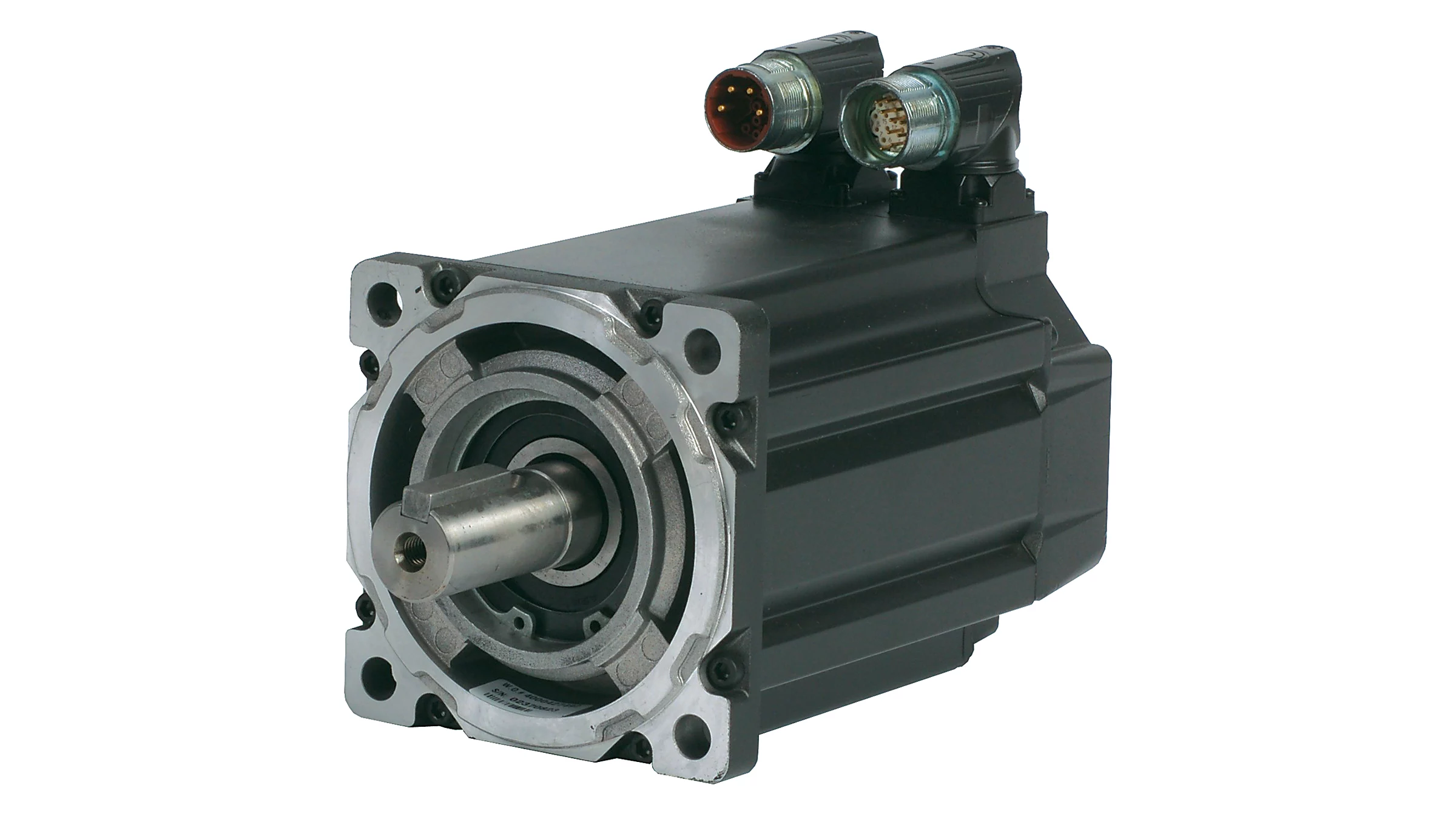
2500PPR 1300W Incremental Type Servo Motor with 220V Driver Kit for 3 Axis CNC Drill for Steel and Aluminium Industrial Machine
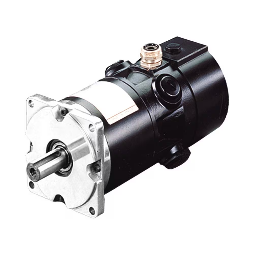
SZGH-13130CC is 1300W servo motor ,optimizing design, compact, beautiful contour, long-term continuous working in rated working mode and economic type
Packing list :
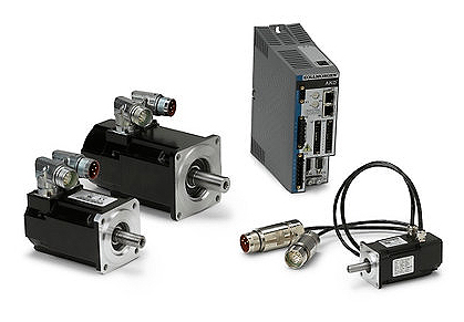
1) SZGH-13130CC 1300w servo motor -1pcs
2) SZGH-SD2026 220v servo driver – 1pcs
3) SZGH1MX-5M 5meter motor cables -1pcs
4) SZGH1EX-5M 5 meter encoder cables -1 pcs
5) Manual -1pcs
Pls tell us at first time when you need :
1) Brake motor
2) Absolutely encoder
3) long cables
4)Ethernet type
Product Description
Application:Automation Machine,Robot Arm,Braided Belt Machine,Computeriaed Flat Knitting Machine,Embroidery Machine,AGV Car,Woodworking Engeaving Machine,CNC Machine…
Product Parameters
| Power(W )Torque(N.m) Speed (rpm) | |||||
| Flange | Model | Power | Torque | Speed | Matched Servo Drive |
| 40mm | SZGH-04005D | 50 | 0.16 | 3000 | SZGH-SD2004 |
| SZGH-5711D | 100 | 0.32 | 3000 | ||
| 60mm | SZGH-06571DC | 200 | 0.6 | 3000 | |
| SZGH-06040DC | 400 | 1.3 | 3000 | ||
| SZGH-06060DC | 600 | 1.9 | 3000 | ||
| 80mm | SZGH-08040DC | 400 | 1.3 | 3000 | SZGH-SD2571 |
| SZGH-08075DC | 750 | 2.4 | 3000 | ||
| SZGH-08075BC | 750 | 3.5 | 2000 | ||
| SZGH-5710CC | 1000 | 4 | 2500 | ||
| 90mm | SZGH-09075DC | 750 | 2.4 | 3000 | |
| SZGH-09075BC | 750 | 3.5 | 2000 | ||
| SZGH-5710CC | 1000 | 4 | 2500 | ||
| 110mm | SZGH-11060DC | 600 | 2 | 3000 | SZGH-SD2026 |
| SZGH-11080DC | 800 | 4 | 2000 | ||
| SZGH11120DC | 1200 | 4 | 3000 | ||
| SZGH-11150DC | 1500 | 5 | 3000 | ||
| SZGH-11120BC | 1200 | 6 | 2000 | ||
| SZGH11180DC | 1800 | 6 | 3000 | ||
| 130mm | SZGH-13100CC | 1000 | 4 | 2500 | |
| SZGH-13130CC | 1300 | 5 | 2500 | ||
| SZGH-13150CC | 1500 | 6 | 2500 | ||
| SZGH-13200CC | 2000 | 77 | 2500 | SZGH-SD2026/ SZGH-SD4038(380V) | |
| SZGH-13100AC | 1000 | 10 | 1000 | ||
| SZGH-13150AC | 1500 | 10 | 1500 | ||
| SZGH-13230AC | 2300 | 15 | 1500 | ||
| SZGH-13260CC | 2600 | 10 | 2500 | ||
| SZGH-13380CC | 3800 | 15 | 2500 | ||
| 150mm | SZGH-15380CC | 3800 | 15 | 2500 | SZGH-4038 |
| SZGH-15300BC | 3000 | 15 | 2000 | ||
| SZGH-15360BC | 3600 | 18 | 2000 | ||
| SZGH-1S470BC | 4700 | 23 | 2000 | SZGH-4075 | |
| SZGH-15550BC | 5500 | 27 | 2000 | ||
| 180mm | SZGH-18270BC | 2700 | 17.2 | 1500 | |
| SZGH-18290BC | 2900 | 27 | 1000 | ||
| SZGH-18300CC | 3000 | 19 | 1500 | ||
| SZGH-18370BC | 3700 | 35 | 1000 | ||
| SZGH-18430AC | 4300 | 27 | 1500 | ||
| SZGH-18450CC | 4500 | 21.5 | 2000 | ||
| SZGH-18550CC | 5500 | 35 | 1500 | ||
| SZGH-18750CC | 7500 | 48 | 1500 | ||
| NOTE : The above models support 2500PPR incremental encoder | |||||
| SD Series | SD2004 | SD2571 | SD2026 | SD4038 | SD4075 |
| Output Power | 50W~600W | 400W~1kW | 600W~3. 8kW | 2kW~3 8KW | 3kW~75kW |
| Input Power | Single/Three Phase AC220V-15%~+10% | Three Phase 380V | |||
| 50/60Hz | |||||
| Control Mode | 0. Position Control: 1 Speed Control; 2: Torque Control: 3:Position/Speed Control; | ||||
| 4:PositionT orque Control: 5:SpeedTorque Control | |||||
| Protective | Over-speed/Over-voltageUnder-voltage Over-current/Overload/Encoder Error/ | ||||
| Function | Control Power Eror/ Position Offset Enor | ||||
| Monitor Function | SpeedPositionPulses /Offset/TorqueCurrent/Status. | ||||
| Digital Input | 1:Servo Enable: 2:Alam Reset: 3:CCW-Forbidden: 4:CW-Forbi dden: 5:Clear | ||||
| Position Ofiset; 6:Pulse Input Forbidden; 7:CCW Torque Limit: 8:CW Torque Limit | |||||
| Digital Output | Servo-Ready On/Alam/ Orientation EndBraker Control | ||||
| Energy Braking | Support buit in Extemal Resistor Braking | ||||
| DriveLoad | Less than 3 times of rotor inertia | ||||
| Display | 5 bits LED Indicator display: 4 Operate keys | ||||
| Communication | RS485 | ||||
| Position Control | Input Mode | 0: Pulse+Direction | |||
| 1:CCW/CW Pulse | |||||
| I . . 2: AB Phase Orthogonal Pulse | |||||
| 1 . 1 3:Inner Position Control | |||||
| Electic Ratio | Numerator of Electric Ratio: 1~32767 | ||||
| Denominator of Electric Ratio: 1~32767 | |||||
| 130mm | SZGH-13100CC/T | 1000 | 4 | 2500 | SZGH-SD2026 |
| SZGH-13130CC/T | 1300 | 5 | 2500 | SZGH-SD2026 | |
| SZGH-13150CC/T | 1500 | 6 | 2500 | SZGH-SD2026 | |
| SZGH-13200CC/T | 2000 | 77 | 2500 | SZGH-SD2026/ SZGH-SD4038(380V) | |
| SZGH-13100AC/T | 1000 | 10 | 1000 | ||
| SZGH-13150AC/T | 1500 | 10 | 1500 | ||
| SZGH-13230AC/T | 2300 | 15 | 1500 | ||
| SZGH-13260CC/T | 2600 | 10 | 2500 | ||
| SZGH-13380CC/T | 3800 | 15 | 2500 | ||
| 150mm | SZGH-15380CC/T | 3800 | 15 | 2500 | SZGH-4038 |
| SZGH-15300BC/T | 3000 | 15 | 2000 | ||
| SZGH-15360BC/T | 3600 | 18 | 2000 | ||
| SZGH-1S470BC/T | 4700 | 23 | 2000 | SZGH-4075 | |
| SZGH-15550BC/T | 5500 | 27 | 2000 | ||
| 180mm | SZGH-18270BC/T | 2700 | 17.2 | 1500 | |
| SZGH-18290BC/T | 2900 | 27 | 1000 | ||
| SZGH-18300CC/T | 3000 | 19 | 1500 | ||
| SZGH-18370BC/T | 3700 | 35 | 1000 | ||
| SZGH-18430AC/T | 4300 | 27 | 1500 | ||
| SZGH-18450CC/T | 4500 | 21.5 | 2000 | ||
| SZGH-18550CC/T | 5500 | 35 | 1500 | ||
| SZGH-18750CC/T | 7500 | 48 | 1500 | ||
| NOTE : The above models support 2500PPR incremental encoder & brake | |||||
Certifications
Packaging & Shipping
1.Industrial packing: plastic bag +foam boxes+ carton +wooden pallets
2.Commercial packing: plastic bag+ foam boxes + carton
3.As the clients requirement
Delivery Detail: Normally ready goods and stock within 2- 5days
Company Profile
HangZhou CHINAMFG Automation CO.,LTD (Formerly known as ‘HangZhou CHINAMFG Automation Co.,Limited(Built in 19 November 2571)’) is 1 of the leading CNC & automatic company in China, specialized in designing projects, marketing, and oversea trading, having extensive experience in CNC package solution, Our focus has been on providing the high quality of Industrial robot arm Lathe CNC system, Milling CNC system, Engraving CNC system, Grinding & router CNC system, Motor & driver, Spindle servo motor & driver, Gear reducer.
SZGH’ products have been in working with a wide variety of CNC machinery and automatic processing equipment with high performance and good precision, stably. We have now established a reliable structure , our experienced engineers and technicians are able to provide professional consultancy and offer you most suitable CNC application solution.
Our strict quality control measures guarantee excellent reliability and high standard of quality. Utilizing advanced CNC machinery to test every product, 100 percent inspection is made before packaging and shipment. Moreover, We also offer flexible lead times to support your business.
We have a large number of customers across Asia, America, the Middle East, Europe, South America, and Africa. Specially we already built own business corporate group in Middle East market.
Our Advantages
Why Choose Us ?
1:more than 10 years development and production, we are manufacturer
2:12-24 month warranty
3: more than 40 patents
4:Free training and easy operation
5: We can response 24 hours as you need
After Sales Service
Best & Professional after- sales supports
Our company have very professional engineers teams ;
We can provide the professional after -sales service to our all clients ;
Here is our engineer Mike solved the problems for our customer ;
Best supports !! Quicly reply !!
Buy at ease , use at ease !!!
FAQ
Q: Do you support CNC system and Robotic Arm System customized manufacturing?
A: Yes,we can customized manufacturing according to customer’s requirment. We support to OEM your own company display interface
and logo.
Q: How long is your CNC System and Robotic Arm System delivery time?
A: Generally it is 3-5 days if the goods are in stock. or it is 5-10 days if the goods are not in stock, it is according to
quantity.10-20 days if customized manufacturing.
Q: Do you provide samples ? is it free or extra ?
A: Yes, we could offer the sample with sample price.
Q: What is your terms of payment ?
A: Payment=1000USD, 70% T/T in advance ,balance before shippment.
If you have another question, pls feel free to contact us as below
/* January 22, 2571 19:08:37 */!function(){function s(e,r){var a,o={};try{e&&e.split(“,”).forEach(function(e,t){e&&(a=e.match(/(.*?):(.*)$/))&&1
| Application: | Machine Tool |
|---|---|
| Speed: | Variable Speed |
| Number of Stator: | Three-Phase |
| Function: | Driving, Control |
| Casing Protection: | Explosion-Proof Type |
| Number of Poles: | 4 |
| Customization: |
Available
|
|
|---|
Where can individuals find reliable resources for learning more about servo motors and their applications?
Individuals interested in learning more about servo motors and their applications can access a variety of reliable resources. These resources provide valuable information, technical knowledge, and practical insights. Here are some places where individuals can find reliable resources for expanding their understanding of servo motors:
1. Manufacturer Websites:
Leading servo motor manufacturers often provide detailed documentation, technical specifications, application notes, and white papers on their websites. These resources offer in-depth information about their products, technologies, and best practices for servo motor applications. Users can visit the websites of prominent manufacturers to access reliable and up-to-date information.
2. Industry Associations and Organizations:
Industry associations and organizations related to automation, robotics, or specific industries often offer educational materials and resources on servo motors. They may provide technical publications, webinars, seminars, and training programs focused on servo motor technology and applications. Examples of such organizations include the International Society of Automation (ISA), the Robotics Industries Association (RIA), and the Society of Automotive Engineers (SAE).
3. Books and Technical Publications:
Books dedicated to servo motor technology, control systems, and industrial automation can provide comprehensive knowledge on the subject. Some recommended titles include “Servo Motors and Industrial Control Theory” by Riazollah Firoozian, “Electric Motors and Drives: Fundamentals, Types, and Applications” by Austin Hughes and Bill Drury, and “Servo Motors and Motion Control: An Introduction” by Albert F. Seabury. Technical publications and journals such as IEEE Transactions on Industrial Electronics and Control Engineering Practice also offer valuable insights and research findings.
4. Online Courses and Training Platforms:
Various online learning platforms offer courses and training programs focused on servo motors and their applications. Websites like Udemy, Coursera, and LinkedIn Learning provide access to video-based courses taught by industry experts. These courses cover topics such as servo motor fundamentals, motion control, programming, and troubleshooting. By enrolling in these courses, individuals can acquire structured knowledge and practical skills related to servo motors.
5. Technical Forums and Discussion Groups:
Participating in technical forums and discussion groups can be an effective way to learn from industry professionals and enthusiasts. Websites like Stack Exchange, Reddit, and engineering-focused forums host discussions on servo motors, where individuals can ask questions, share experiences, and gain insights from the community. It’s important to verify the credibility of the information shared in such forums and rely on responses from trusted contributors.
6. Trade Shows and Conferences:
Attending trade shows, exhibitions, and conferences related to automation, robotics, or specific industries can provide opportunities to learn about servo motors. These events often feature presentations, workshops, and demonstrations by industry experts and manufacturers. Participants can gain hands-on experience, interact with professionals, and stay updated with the latest advancements in servo motor technology.
By leveraging these reliable resources, individuals can deepen their knowledge and understanding of servo motors and their applications. It is advisable to consult multiple sources and cross-reference information to ensure a comprehensive understanding of the subject.
Are there different types of servo motors, and how do they differ?
Yes, there are different types of servo motors available, each with its own characteristics and applications. The variations among servo motors can be attributed to factors such as construction, control mechanisms, power requirements, and performance specifications. Let’s explore some of the common types of servo motors and how they differ:
1. DC Servo Motors:
DC servo motors are widely used in various applications. They consist of a DC motor combined with a feedback control system. The control system typically includes a position or velocity feedback sensor, such as an encoder or a resolver. DC servo motors offer good speed and torque control and are often employed in robotics, automation, and hobbyist projects. They can be operated with a separate motor driver or integrated into servo motor units with built-in control electronics.
2. AC Servo Motors:
AC servo motors are designed for high-performance applications that require precise control and fast response times. They are typically three-phase motors and are driven by sinusoidal AC waveforms. AC servo motors often incorporate advanced control algorithms and feedback systems to achieve accurate position, velocity, and torque control. These motors are commonly used in industrial automation, CNC machines, robotics, and other applications that demand high precision and dynamic performance.
3. Brushed Servo Motors:
Brushed servo motors feature a traditional brushed DC motor design. They consist of a rotor with a commutator and carbon brushes that make physical contact with the commutator. The brushes provide electrical connections, allowing the motor’s magnetic field to interact with the rotor’s windings. Brushed servo motors are known for their simplicity and cost-effectiveness. However, they may require more maintenance due to brush wear, and they generally have lower efficiency and shorter lifespan compared to brushless servo motors.
4. Brushless Servo Motors:
Brushless servo motors, also known as brushless DC (BLDC) motors, offer several advantages over brushed motors. They eliminate the need for brushes and commutators, resulting in improved reliability, higher efficiency, and longer lifespan. Brushless servo motors rely on electronic commutation, typically using Hall effect sensors or encoder feedback for accurate rotor position detection. These motors are widely used in robotics, industrial automation, aerospace, and other applications that require high-performance motion control with minimal maintenance.
5. Linear Servo Motors:
Linear servo motors are designed to provide linear motion instead of rotational motion. They consist of a primary part (stator) and a secondary part (slider or forcer) that interact magnetically to generate linear motion. Linear servo motors offer advantages such as high speed, high acceleration, and precise positioning along a linear axis. They find applications in various industries, including semiconductor manufacturing, packaging, printing, and machine tools.
6. Micro Servo Motors:
Micro servo motors are small-sized servo motors often used in applications with limited space and low power requirements. They are commonly found in hobbyist projects, model airplanes, remote-controlled vehicles, and small robotic systems. Micro servo motors are lightweight, compact, and offer reasonable precision and control for their size.
These are some of the different types of servo motors available, each catering to specific applications and requirements. The choice of servo motor type depends on factors such as the desired performance, accuracy, power requirements, environmental conditions, and cost considerations. Understanding the differences between servo motor types is essential for selecting the most suitable motor for a particular application.
Can you explain the difference between a servo motor and a regular electric motor?
A servo motor and a regular electric motor are both types of electric motors, but they have distinct differences in terms of design, control, and functionality.
A regular electric motor, also known as an induction motor or a DC motor, is designed to convert electrical energy into mechanical energy. It consists of a rotor, which rotates, and a stator, which surrounds the rotor and generates a rotating magnetic field. The rotor is connected to an output shaft, and when current flows through the motor’s windings, it creates a magnetic field that interacts with the stator’s magnetic field, resulting in rotational motion.
On the other hand, a servo motor is a more specialized type of electric motor that incorporates additional components for precise control of position, speed, and acceleration. It consists of a regular electric motor, a sensor or encoder, and a feedback control system. The sensor or encoder provides feedback on the motor’s current position, and this information is used by the control system to adjust the motor’s behavior.
The key difference between a servo motor and a regular electric motor lies in their control mechanisms. A regular electric motor typically operates at a fixed speed based on the voltage and frequency of the power supply. In contrast, a servo motor can be controlled to rotate to a specific angle or position and maintain that position accurately. The control system continuously monitors the motor’s actual position through the feedback sensor and adjusts the motor’s operation to achieve the desired position or follow a specific trajectory.
Another distinction is the torque output of the motors. Regular electric motors generally provide high torque at low speeds and lower torque at higher speeds. In contrast, servo motors are designed to deliver high torque at both low and high speeds, which makes them suitable for applications that require precise and dynamic motion control.
Furthermore, servo motors often have a more compact and lightweight design compared to regular electric motors. They are commonly used in applications where precise positioning, speed control, and responsiveness are critical, such as robotics, CNC machines, automation systems, and remote-controlled vehicles.
In summary, while both servo motors and regular electric motors are used to convert electrical energy into mechanical energy, servo motors offer enhanced control capabilities, precise positioning, and high torque at various speeds, making them well-suited for applications that require accurate and dynamic motion control.


editor by CX 2024-05-15
China best Sg92r Analog Servo 9g Motor Arm Set Kit supplier
Product Description
Return policy details
- Buyers can return item(s) for a refund within 7 days from the day the item(s) were received, and the buyer is to afford the return shipping cost. The item(s) must be returned in the same exact condition as once it was delivered.
- Buyers may return the item(s) for a refund if they are not as described or with quality issues within 7 days from the day the item(s) were received.The buyer is required to afford the return shipping cost, based on the condition of the item(s) received.
Description
| SKU | 10A044 |
| Place of Origin | China |
| MOQ | 5 |
| Delivery time | 7days |
| Support customization | yes |
FAQ
1.Are you manufacturer ?
Yes, We Are Manufacturer & Trading Company
2.How long is your delivery time?
Normally 3-5 working days after payment; Special requirement orders, delivery time is negotiable.
3.Do you accept OEM design?
Yes, we do. We can design according to your requirement, MOQ usually 500-1000.
4.What payment terms you accept?
We accept Alibaba Trade Assuarce, T/T, PayPal, Western Union, Wechat, Alipay, in Cash (RMB or USD).
5.What Express Company You Use ?
We Can Ship the goods Via DHL, Fedex ,TNT, UPS ,Aramex ,EMS , China Post , By Sea And By Air.
Company Profile
Exhibition
Certification
Product Packaging
Payment & Delivery Team
Contact Us
/* January 22, 2571 19:08:37 */!function(){function s(e,r){var a,o={};try{e&&e.split(“,”).forEach(function(e,t){e&&(a=e.match(/(.*?):(.*)$/))&&1
| Type: | Electronic Accessories |
|---|---|
| Electronics: | Robot |
| Vinyl: | Standard |
| Suitable for: | Adult |
| Sku: | 10A044 |
| Place of Origin: | China |
| Samples: |
US$ 2.7/Piece
1 Piece(Min.Order) | |
|---|

What maintenance practices are recommended for ensuring the longevity of servo motors?
Maintaining servo motors properly is crucial to ensure their longevity and reliable performance. Here are some recommended maintenance practices:
1. Regular Cleaning:
Regularly clean the servo motor to remove dust, debris, and other contaminants that can affect its performance. Use a soft brush or compressed air to clean the motor’s exterior and ventilation ports. Avoid using excessive force or liquid cleaners that could damage the motor.
2. Lubrication:
Follow the manufacturer’s recommendations for lubrication intervals and use the appropriate lubricant for the motor. Lubricate the motor’s bearings, gears, and other moving parts as per the specified schedule. Proper lubrication reduces friction, minimizes wear, and helps maintain optimal performance.
3. Inspections:
Regularly inspect the servo motor for signs of wear, damage, or loose connections. Check for any unusual noises, vibrations, or overheating during operation, as these can indicate potential issues. If any abnormalities are detected, consult the manufacturer’s documentation or seek professional assistance for further evaluation and repair.
4. Electrical Connections:
Ensure that all electrical connections to the servo motor, such as power cables and signal wires, are secure and properly insulated. Loose or damaged connections can lead to electrical problems, voltage fluctuations, or signal interference, which can affect the motor’s performance and longevity.
5. Environmental Considerations:
Take into account the operating environment of the servo motor. Ensure that the motor is protected from excessive moisture, dust, extreme temperatures, and corrosive substances. If necessary, use appropriate enclosures or protective measures to safeguard the motor from adverse environmental conditions.
6. Software and Firmware Updates:
Stay updated with the latest software and firmware releases provided by the servo motor manufacturer. These updates often include bug fixes, performance enhancements, and new features that can improve the motor’s functionality and reliability. Follow the manufacturer’s instructions for safely updating the motor’s software or firmware.
7. Training and Documentation:
Ensure that personnel responsible for the maintenance of servo motors are properly trained and familiar with the manufacturer’s guidelines and documentation. This includes understanding recommended maintenance procedures, safety precautions, and troubleshooting techniques. Regular training and access to up-to-date documentation are essential for effective servo motor maintenance.
8. Professional Servicing:
If a servo motor requires complex repairs or servicing beyond regular maintenance, it is advisable to consult a qualified technician or contact the manufacturer’s service center. Attempting to repair or modify the motor without proper expertise can lead to further damage or safety hazards.
By following these maintenance practices, servo motors can operate optimally and have an extended lifespan. Regular cleaning, lubrication, inspections, secure electrical connections, environmental considerations, software updates, training, and professional servicing all contribute to ensuring the longevity and reliable performance of servo motors.
Can you explain the concept of torque and speed in relation to servo motors?
Torque and speed are two essential parameters in understanding the performance characteristics of servo motors. Let’s explore these concepts in relation to servo motors:
Torque:
Torque refers to the rotational force produced by a servo motor. It determines the motor’s ability to generate rotational motion and overcome resistance or load. Torque is typically measured in units of force multiplied by distance, such as Nm (Newton-meter) or oz-in (ounce-inch).
The torque output of a servo motor is crucial in applications where the motor needs to move or control a load. The motor must provide enough torque to overcome the resistance or friction in the system and maintain the desired position or motion. Higher torque allows the motor to handle heavier loads or more challenging operating conditions.
It is important to note that the torque characteristics of a servo motor may vary depending on the speed or position of the motor. Manufacturers often provide torque-speed curves or torque-position curves, which illustrate the motor’s torque capabilities at different operating points. Understanding these curves helps in selecting a servo motor that can deliver the required torque for a specific application.
Speed:
Speed refers to the rotational velocity at which a servo motor operates. It indicates how fast the motor can rotate and how quickly it can achieve the desired position or motion. Speed is typically measured in units of revolutions per minute (RPM) or radians per second (rad/s).
The speed of a servo motor is crucial in applications that require rapid movements or high-speed operations. It determines the motor’s responsiveness and the system’s overall performance. Different servo motors have different speed capabilities, and the maximum achievable speed is often specified by the manufacturer.
It is worth noting that the speed of a servo motor may also affect its torque output. Some servo motors exhibit a phenomenon known as “speed-torque curve,” where the motor’s torque decreases as the speed increases. This behavior is influenced by factors such as motor design, winding resistance, and control algorithms. Understanding the speed-torque characteristics of a servo motor is important for selecting a motor that can meet the speed requirements of the application while maintaining sufficient torque.
Overall, torque and speed are interrelated parameters that determine the performance capabilities of a servo motor. The torque capability determines the motor’s ability to handle loads, while the speed capability determines how quickly the motor can achieve the desired motion. When selecting a servo motor, it is essential to consider both the torque and speed requirements of the application to ensure that the motor can deliver the desired performance.
How does feedback control work in a servo motor system?
In a servo motor system, feedback control plays a crucial role in achieving precise control over the motor’s position, speed, and acceleration. The feedback control loop consists of several components that work together to continuously monitor and adjust the motor’s behavior based on the desired and actual position information. Here’s an overview of how feedback control works in a servo motor system:
1. Position Reference:
The servo motor system starts with a position reference or a desired position. This can be specified by a user or a control system, depending on the application requirements. The position reference represents the target position that the servo motor needs to reach and maintain.
2. Feedback Sensor:
A feedback sensor, such as an encoder or resolver, is attached to the servo motor’s shaft. The purpose of the feedback sensor is to continuously measure the motor’s actual position and provide feedback to the control system. The sensor generates signals that indicate the motor’s current position, allowing the control system to compare it with the desired position.
3. Control System:
The control system receives the position reference and the feedback signals from the sensor. It processes this information to determine the motor’s current position error, which is the difference between the desired position and the actual position. The control system calculates the required adjustments to minimize this position error and bring the motor closer to the desired position.
4. Controller:
The controller is a key component of the feedback control loop. It receives the position error from the control system and generates control signals that govern the motor’s behavior. The controller adjusts the motor’s inputs, such as voltage or current, based on the position error and control algorithm. The control algorithm can be implemented using various techniques, such as proportional-integral-derivative (PID) control, which adjusts the motor’s inputs based on the current error, the integral of past errors, and the rate of change of errors.
5. Motor Drive:
The control signals generated by the controller are sent to the motor drive unit, which amplifies and converts these signals into appropriate voltage or current levels. The motor drive unit provides the necessary power and control signals to the servo motor to initiate the desired motion. The drive unit adjusts the motor’s inputs based on the control signals to achieve the desired position, speed, and acceleration specified by the control system.
6. Motor Response:
As the motor receives the adjusted inputs from the motor drive, it starts to rotate and move towards the desired position. The motor’s response is continually monitored by the feedback sensor, which measures the actual position in real-time.
7. Feedback Comparison:
The feedback sensor compares the actual position with the desired position. If there is any deviation, the sensor generates feedback signals reflecting the discrepancy between the desired and actual positions. These signals are fed back to the control system, allowing it to recalculate the position error and generate updated control signals to further adjust the motor’s behavior.
This feedback loop continues to operate in a continuous cycle, with the control system adjusting the motor’s inputs based on the feedback information. As a result, the servo motor can accurately track and maintain the desired position, compensating for any disturbances or variations that may occur during operation.
In summary, feedback control in a servo motor system involves continuously comparing the desired position with the actual position using a feedback sensor. The control system processes this position error and generates control signals, which are converted and amplified by the motor drive unit to drive the motor. The motor’s response is monitored by the feedback sensor, and any discrepancies are fed back to the control system, enabling it to make further adjustments. This closed-loop control mechanism ensures precise positioning and accurate control of the servo motor.
editor by CX 2024-05-14
China Hot selling High Power High Accuracy Electric Car Kit 600W 2n. M 2.5A 220V AC Servo Motor Fit Rear Axle for Electrical Fan, Electric Washing Machine with Best Sales
Product Description
High Power High Accuracy electric car kit 600w 2n.m 2.5A 220V AC servo motor fit rear axle for Electrical Fan, Electric Washing Machine
SZGH-11060DC is 600 W servo motor ,optimizing design, compact, beautiful contour, long-term continuous working in rated working mode and economic type
Product Description
,Packing list :
1) SZGH-11060DC 600w servo motor -1pcs
2) SZGH-SD2004 220v servo driver – 1pcs
3) SZGH1MX-5M 5meter motor cables -1pcs
4) SZGH1EX-5M 5 meter encoder cables -1 pcs
5) Manual -1pcs
Pls tell us at first time when you need :
1) Brake motor
2) Absolutely encoder
3) long cables
Detailed Photos
Product Parameters
Description of Driver
Input Power : Single Three Phase AC220V-15%~+10% SO/60HZ
Control model :
0: Position Control; 1:Speed Control;
2: Torque Control; 3:Position/Speed Control;
4·PositionTorque Control: 5:Speed Torque Control
Protective Function : Over-speed Over-voltage Under-voltage Over-current OverloadEncoder Error/ Control Power Eror/ Position Offset Eror
Driver Load : Less than 3times of rotor inertia
Display : 5 bits LED indicator display 4 Operate keys
Communication : RS485
Position Control : Input Model , Electric Ratio
Certifications
Company Profile
HangZhou CHINAMFG Automation CO.,LTD (Formerly known as ‘HangZhou CHINAMFG Automation Co.,Limited(Built in 19 November 2571)’) is 1 of the leading CNC & automatic company in China, specialized in designing projects, marketing, and oversea trading, having extensive experience in CNC package solution, Our focus has been on providing the high quality of Industrial robot arm Lathe CNC system, Milling CNC system, Engraving CNC system, Grinding & router CNC system, Motor & driver, Spindle servo motor & driver, Gear reducer.
SZGH’ products have been in working with a wide variety of CNC machinery and automatic processing equipment with high performance and good precision, stably. We have now established a reliable structure , our experienced engineers and technicians are able to provide professional consultancy and offer you most suitable CNC application solution.
Our strict quality control measures guarantee excellent reliability and high standard of quality. Utilizing advanced CNC machinery to test every product, 100 percent inspection is made before packaging and shipment. Moreover, We also offer flexible lead times to support your business.
We have a large number of customers across Asia, America, the Middle East, Europe, South America, and Africa. Specially we already built own business corporate group in Middle East market.
Our Advantages
After Sales Service
Best & Professional after- sales supports
Our company have very professional engineers teams ;
We can provide the professional after -sales service to our all clients ;
Here is our engineer Mike solved the problems for our customer ;
Best supports !! Quicly reply !!
Buy at ease , use at ease !!!
FAQ
1. Who are we?
We are based in ZheJiang , China, start from 2013, which providing cnc total solutions&Robot arm, sell to Eastern Europe(20.00%),Mid East(20.00%),Southeast Asia(15.00%),Southern Europe(10.00%),South America(8.00%),North America(5.00%),Western Europe(5.00%),Eastern Asia(4.00%),Central America(4.00%),Northern Europe(4.00%),Africa(3.00%),Domestic Market(2.00%).
2. How can we guarantee quality?
Always finishing a pre full testing by our professional engineers;
Always final 100% Inspection before shipment;
3.What can you buy from us?
CNC Controller/Servo Motor & Servo Driver/Spindle Servo Motor & Spindle Servo Drive/Robot Arms
4. Why should you buy from us not from other suppliers?
We can provide with suitable package solution by CNC system and motor, drivers; Guanhong has professional technical team,customized design,high quality guarantee,competitive quotation, honest and reliable business is our tenet. Your satisfy is our greatest .
5. What services can we provide?
Accepted Delivery Terms: FOB,CFR,CIF,EXW,FAS,CIP,FCA,DDP,DDU,DAF;
Accepted Payment Currency:USD,EUR,CAD,HKD,CNY;
Accepted Payment Type: T/T,L/C,D/P D/A,Credit Card,PayPal,Western Union,Cash,Escrow;
Language Spoken:English,Chinese,Spanish,Japanese,Portuguese,German,Arabic,French,Russian,Korean,Italian and so on.
6.When can you receive our order?
All goods will be produced well within 5 to 7 workdays, except the customized products.
/* January 22, 2571 19:08:37 */!function(){function s(e,r){var a,o={};try{e&&e.split(“,”).forEach(function(e,t){e&&(a=e.match(/(.*?):(.*)$/))&&1
| Application: | Machine Tool |
|---|---|
| Speed: | Variable Speed |
| Number of Stator: | Single-Phase |
| Function: | Driving, Control |
| Casing Protection: | Explosion-Proof Type |
| Number of Poles: | 4 |
| Customization: |
Available
|
|
|---|
Are there advancements or trends in servo motor technology that users should be aware of?
Yes, there have been significant advancements and emerging trends in servo motor technology that users should be aware of. These developments aim to enhance performance, improve efficiency, and provide new capabilities. Here are some noteworthy advancements and trends in servo motor technology:
1. Higher Power Density:
Advancements in servo motor design and manufacturing techniques have led to higher power densities. This means that modern servo motors can deliver more power in a smaller and lighter package. Higher power density allows for more compact and efficient machine designs, particularly in applications with limited space or weight restrictions.
2. Improved Efficiency:
Efficiency is a crucial aspect of servo motor technology. Manufacturers are continuously striving to improve motor efficiency to minimize energy consumption and reduce operating costs. Advanced motor designs, optimized winding configurations, and the use of high-quality materials contribute to higher efficiency levels, resulting in energy savings and lower heat generation.
3. Integration of Electronics and Control:
Integration of electronics and control functions directly into servo motors is becoming increasingly common. This trend eliminates the need for external motor controllers or drives, simplifies wiring and installation, and reduces overall system complexity. Integrated servo motors often include features such as on-board motion control, communication interfaces, and safety features.
4. Digitalization and Connectivity:
Servo motor technology is embracing digitalization and connectivity trends. Many modern servo motors come equipped with digital interfaces, such as Ethernet or fieldbus protocols, enabling seamless integration with industrial communication networks. This connectivity allows for real-time monitoring, diagnostics, and remote control of servo motors, facilitating condition monitoring, predictive maintenance, and system optimization.
5. Advanced Feedback Systems:
Feedback systems play a critical role in servo motor performance. Recent advancements in feedback technology have resulted in more accurate and higher-resolution encoders, resolvers, and sensors. These advanced feedback systems provide precise position and velocity information, enabling improved motion control, better accuracy, and enhanced dynamic response in servo motor applications.
6. Smart and Adaptive Control Algorithms:
Servo motor control algorithms have evolved to include smart and adaptive features. These algorithms can adapt to changing load conditions, compensate for disturbances, and optimize motor performance based on real-time feedback. Smart control algorithms contribute to smoother operation, increased stability, and improved tracking accuracy in various applications.
7. Safety and Functional Safety:
Safety is a paramount concern in industrial automation. Servo motor technology has incorporated safety features and functional safety standards to ensure the protection of personnel and equipment. Safety-rated servo motors often include features such as safe torque off (STO) functionality, safe motion control, and compliance with safety standards like ISO 13849 and IEC 61508.
It’s important for users to stay informed about these advancements and trends in servo motor technology. By understanding the latest developments, users can make informed decisions when selecting and implementing servo motors, leading to improved performance, efficiency, and reliability in their applications.
What factors should be considered when selecting a servo motor for a specific application?
When selecting a servo motor for a specific application, several factors need to be considered. These factors help ensure that the chosen servo motor meets the requirements and performs optimally in the intended application. Here are some key factors to consider:
1. Torque and Power Requirements:
One of the primary considerations is the torque and power requirements of the application. The servo motor should be able to generate sufficient torque to handle the load and overcome any resistance or friction in the system. Additionally, the power rating of the motor should match the power supply available in the application. It is essential to evaluate the torque-speed characteristics of the servo motor to ensure it can deliver the required performance.
2. Speed and Acceleration:
The required speed and acceleration capabilities of the servo motor should align with the application’s needs. Different applications have varying speed and acceleration requirements, and the servo motor should be able to meet these demands. It is crucial to consider both the maximum speed that the motor can achieve and the time it takes to accelerate or decelerate to specific speeds. Evaluating the servo motor’s speed-torque characteristics and acceleration capabilities is necessary for selecting the right motor.
3. Positioning Accuracy and Repeatability:
The desired positioning accuracy and repeatability of the application play a significant role in servo motor selection. If precise positioning is crucial, a servo motor with high accuracy and low positioning errors should be chosen. The feedback mechanism, such as encoders or resolvers, should provide the required resolution to achieve the desired accuracy. Repeatability, the ability to consistently reach the same position, should also be considered, especially in applications where repetitive movements are necessary.
4. Environmental Conditions:
The environmental conditions in which the servo motor will operate should be taken into account. Factors such as temperature extremes, humidity, dust, and vibration can affect the motor’s performance and lifespan. In harsh environments, it may be necessary to choose a servo motor with appropriate protection ratings, such as IP (Ingress Protection) ratings, to ensure reliable operation and longevity.
5. Control System Compatibility:
The compatibility of the servo motor with the control system used in the application is crucial. The motor should be compatible with the control signals and communication protocols employed in the system. This includes considerations such as voltage compatibility, control signal types (analog, digital, pulse), and communication interfaces (such as Ethernet, CAN, or Modbus). Ensuring compatibility will facilitate seamless integration and efficient control of the servo motor within the application.
6. Size and Weight Constraints:
The physical size and weight limitations of the application should be considered when selecting a servo motor. The motor’s dimensions should fit within the available space, and its weight should not exceed the application’s weight capacity. Compact and lightweight servo motors may be preferred in applications where space is limited or weight is a critical factor.
7. Cost Considerations:
The cost of the servo motor and its overall value for the application should be evaluated. It is essential to consider the initial purchase cost as well as the long-term maintenance and operational costs. While cost is a factor, it should not be the sole determining factor, as compromising on quality or performance may lead to suboptimal results.
By considering these factors, one can make an informed decision when selecting a servo motor for a specific application. It is recommended to consult with manufacturers or experts in the field to ensure the chosen servo motor meets the application’s requirements and provides reliable and efficient performance.
What is a servo motor, and how does it function in automation systems?
A servo motor is a type of motor specifically designed for precise control of angular or linear position, velocity, and acceleration. It is widely used in various automation systems where accurate motion control is required. Let’s explore the concept of servo motors and how they function in automation systems:
A servo motor consists of a motor, a position feedback device (such as an encoder or resolver), and a control system. The control system receives input signals, typically in the form of electrical pulses or analog signals, indicating the desired position or speed. Based on these signals and the feedback from the position sensor, the control system adjusts the motor’s operation to achieve the desired motion.
The functioning of a servo motor in an automation system involves the following steps:
- Signal Input: The automation system provides a control signal to the servo motor, indicating the desired position, speed, or other motion parameters. This signal can be generated by a human operator, a computer, a programmable logic controller (PLC), or other control devices.
- Feedback System: The servo motor incorporates a position feedback device, such as an encoder or resolver, which continuously monitors the motor’s actual position. This feedback information is sent back to the control system, allowing it to compare the actual position with the desired position specified by the input signal.
- Control System: The control system, typically housed within the servo motor or an external servo drive, receives the input signal and the feedback from the position sensor. It processes this information and generates the appropriate control signals to the motor.
- Motor Operation: Based on the control signals received from the control system, the servo motor adjusts its operation to achieve the desired motion. The control system varies the motor’s voltage, current, or frequency to control the motor’s speed, torque, or position accurately.
- Closed-Loop Control: Servo motors operate in a closed-loop control system. The feedback information from the position sensor allows the control system to continuously monitor and adjust the motor’s operation to minimize any deviation between the desired position and the actual position. This closed-loop control mechanism provides high accuracy, repeatability, and responsiveness in motion control applications.
One of the key advantages of servo motors in automation systems is their ability to provide precise and dynamic motion control. They can rapidly accelerate, decelerate, and change direction with high accuracy, allowing for intricate and complex movements. Servo motors are widely used in applications such as robotics, CNC machines, printing presses, packaging equipment, and automated manufacturing systems.
In summary, a servo motor is a specialized motor that enables accurate control of position, velocity, and acceleration in automation systems. Through the combination of a control system and a position feedback device, servo motors can precisely adjust their operation to achieve the desired motion. Their closed-loop control mechanism and high responsiveness make them an essential component in various applications requiring precise and dynamic motion control.
editor by CX 2024-04-11
China supplier 204mm Length 220V 3000rpm Three-Phase Servo Motor Kit with high quality
Product Description
Product Description
220v 1.5kw 5NM 3000rpm AC Servo motor driver kit
This product set includes motor with driver and 3m cable default. longer cable available in charge.
This ac servo motor selects high working temperature, high magnetic energy and high quality permanent magnet materials. The effective element method is used to optimize the electromagnetic parameter design. It is driven by sinusoidal current and has good operation performance. It is widely used in spark machine, manipulator and precise machine. Can add speed reducer, lead mechanical equipment to bring reliable accuracy and high torque. Good speed control, highest output power per unit weight and volume. The torque fluctuation of multistage structure is small, and the power can be done from 100W to 10KW.
DM series drivers adopt double PCB platemaking performance more stable, digital tube real-time display speed, key can real-time change driving parameters; Three anti – paint after surface spraying of circuit board; Dust, moisture, anti – static, anti – evil environment. The driver is equipped with well TI chip, ruby electrolytic capacitor power supply filter and IPM module. Can add serial port function, achieve 485 communication function.
Related Products
| Model no. | Rated Voltage(V) | Output Power(w) | Rated Torque(N.m) | Rated Speed(RPM) |
Encoder (Increment) PPR |
Motor Length(mm) | Shaft DIA(mm) | Matched Driver |
| XK110AEA12571-SH3 | 220 | 1200 | 6 | 2000 | 2500 | 219 | 19 | DM-12EA |
| XK110AEA12030-SH3 | 220 | 1200 | 4 | 3000 | 2500 | 189 | 19 | DM-26EA |
| 110AEA15030-SH3 | 220 | 1500 | 5 | 3000 | 2500 | 204 | 19 | DM-26EA |
| 110AEA18030-SH3 | 220 | 1800 | 6 | 3000 | 2500 | 219 | 19 | DM-26EA |
Size
Size of Driver:
The front panel:
The function of AC servo motor driver.
| The input power | Single phase or 3 phase AC220V -15~+10% 50/60Hz | |
| environment | temperature | Using: 0~55 Storage: -20~80 |
| humidity | Below 90% RH No dewing | |
| vibration | Belown0.5G(4.9m/S2),10-60 no continue running | |
| Control mode |
1 Torque mode (internal or external) 6 Speed/torque model |
| Control input |
servo enables,alarm reset, Forward driving is prohibited, Reverse driving is prohibited , External CHINAMFG torque is limited , external reverse torque is limited, Emergency stop, Zero speed clamp , 1 Internal speed command option 1, 2 Internal speed command option 2 3 Internal speed command option 3, 1 The internal torque command option 1 2 The internal torque command option 2 Control mode switch, Gain switch, 1 Electronic gear molecular option 1, 2 Electronic gear molecular option 2,Instructions for, Position deviation to clear, Pulse input is prohibited, Proportional control, The CHINAMFG return to trigger, The CHINAMFG return reference point. 1 Internal location option 1, 2 Internal location option 2, Trigger internal position command, Suspend internal position command |
| Control the output |
Alarm detection, Servo ready, Emergency stop checked out, Positioning to complete, Speed to reach, Reach the predetermined torque, Zero speed detection, Servo motor current, Electromagnetic brake, The CHINAMFG return to complete, Located close to, torque limit, speed limit, Tracking arrive torque command |
| The encoder feedback | 2500p/r,15 line increment model, differential output |
| Communication mode | RS-232 OR RS-485 |
| Display and operation | 1.five LED display 2.Four buttons |
| Braking way | Through the internal/external braking resistance braking energy |
| Cooling way | Air cooled (heat transfer film, the strong cold wind fan) |
| Power range | ≤7.5KW |
Installation environment conditions
1.Working environment: 0 ~ and ;working environment: less than 80% (no condensation)
2.Storage environment temperature:- ; Storage environment humidity: 80% of the (no condensation)
3.Vibration: Below 0.5 G
4.Well ventilated, less moisture and dust place
5.No corrosive, flash gas, oil and gas, cuttingfluid, iron powder and so on environment
6.No moisture and direct sunlight place
Installation method
1.Level installation:to avoid liquids such as water, oil from motor wire end into the motor internal, please will cable outlet inbelow
2.Vertical installation: if the motor shaft and the installation with reduction unit, must pay attention to and prevent reducer in mark through the motor shaft into the motor internal
3.The motor shaft out quantitymust be thoroughly, if insufficient out to motor sports generates vibration
4.Installation and remove the motor, please do not use hammer knock motor, otherwise easy to cause damage to themotor shaft and encoder
The motor direction of rotation
Looking from the motor load on the motor shaft and counterclockwise (CCW) for the forward, clockwise (the CW) as the reverse
Packaging & Shipping
Company Information
Certifications
Our Services
/* January 22, 2571 19:08:37 */!function(){function s(e,r){var a,o={};try{e&&e.split(“,”).forEach(function(e,t){e&&(a=e.match(/(.*?):(.*)$/))&&1
| Application: | CNC |
|---|---|
| Speed: | 1500rpm-2500rpm |
| Type: | Servo Motor |
| Customization: |
Available
|
|
|---|
.shipping-cost-tm .tm-status-off{background: none;padding:0;color: #1470cc}
|
Shipping Cost:
Estimated freight per unit. |
about shipping cost and estimated delivery time. |
|---|
| Payment Method: |
|
|---|---|
|
Initial Payment Full Payment |
| Currency: | US$ |
|---|
| Return&refunds: | You can apply for a refund up to 30 days after receipt of the products. |
|---|
What role does the controller play in the overall performance of a servo motor?
The controller plays a crucial role in the overall performance of a servo motor system. It is responsible for monitoring and regulating the motor’s operation to achieve the desired motion and maintain system stability. Let’s explore in detail the role of the controller in the performance of a servo motor:
1. Motion Control:
The controller is responsible for generating precise control signals that dictate the motor’s speed, torque, and position. It receives input commands from the user or higher-level control system and translates them into appropriate control signals for the servo motor. By accurately controlling the motor’s motion, the controller enables precise positioning, smooth acceleration and deceleration, and the ability to follow complex trajectories. The controller’s effectiveness in generating accurate and responsive control signals directly impacts the motor’s motion control capabilities.
2. Feedback Control:
The controller utilizes feedback from position sensors, such as encoders, to monitor the motor’s actual position, speed, and other parameters. It compares the desired motion profile with the actual motor behavior and continuously adjusts the control signals to minimize any deviations or errors. This closed-loop feedback control mechanism allows the controller to compensate for disturbances, variations in load conditions, and other factors that may affect the motor’s performance. By continuously monitoring and adjusting the control signals based on feedback, the controller helps maintain accurate and stable motor operation.
3. PID Control:
Many servo motor controllers employ Proportional-Integral-Derivative (PID) control algorithms to regulate the motor’s behavior. PID control calculates control signals based on the error between the desired setpoint and the actual motor response. The proportional term responds to the present error, the integral term accounts for accumulated past errors, and the derivative term considers the rate of change of the error. By tuning the PID parameters, the controller can achieve optimal performance in terms of response time, stability, and steady-state accuracy. Properly configured and tuned PID control greatly influences the servo motor’s ability to follow commands accurately and efficiently.
4. Trajectory Planning:
In applications requiring complex motion profiles or trajectories, the controller plays a vital role in trajectory planning. It determines the optimal path and speed profile for the motor to follow, taking into account constraints such as acceleration limits, jerk limits, and mechanical limitations. The controller generates the required control signals to achieve the desired trajectory, ensuring smooth and precise motion. Effective trajectory planning by the controller enhances the motor’s performance in applications that involve intricate or high-speed movements.
5. System Monitoring and Protection:
The controller monitors various parameters of the servo motor system, including temperature, current, voltage, and other diagnostic information. It incorporates protective measures to prevent damage or excessive stress on the motor. The controller can implement safety features such as overcurrent protection, over-temperature protection, and fault detection mechanisms. By actively monitoring and safeguarding the motor and the system, the controller helps prevent failures, prolongs the motor’s lifespan, and ensures safe and reliable operation.
6. Communication and Integration:
The controller facilitates communication and integration with other components or systems within the overall automation setup. It may support various communication protocols, such as Ethernet, CAN bus, or fieldbus protocols, enabling seamless integration with higher-level control systems, human-machine interfaces (HMIs), or other peripheral devices. The controller’s ability to efficiently exchange data and commands with other system components allows for coordinated and synchronized operation, enhancing the overall performance and functionality of the servo motor system.
In summary, the controller plays a vital role in the overall performance of a servo motor system. It enables precise motion control, utilizes feedback for closed-loop control, implements PID control algorithms, plans complex trajectories, monitors system parameters, and facilitates communication and integration. The controller’s capabilities and effectiveness directly impact the motor’s performance in terms of accuracy, responsiveness, stability, and overall system efficiency.
Are there different types of servo motors, and how do they differ?
Yes, there are different types of servo motors available, each with its own characteristics and applications. The variations among servo motors can be attributed to factors such as construction, control mechanisms, power requirements, and performance specifications. Let’s explore some of the common types of servo motors and how they differ:
1. DC Servo Motors:
DC servo motors are widely used in various applications. They consist of a DC motor combined with a feedback control system. The control system typically includes a position or velocity feedback sensor, such as an encoder or a resolver. DC servo motors offer good speed and torque control and are often employed in robotics, automation, and hobbyist projects. They can be operated with a separate motor driver or integrated into servo motor units with built-in control electronics.
2. AC Servo Motors:
AC servo motors are designed for high-performance applications that require precise control and fast response times. They are typically three-phase motors and are driven by sinusoidal AC waveforms. AC servo motors often incorporate advanced control algorithms and feedback systems to achieve accurate position, velocity, and torque control. These motors are commonly used in industrial automation, CNC machines, robotics, and other applications that demand high precision and dynamic performance.
3. Brushed Servo Motors:
Brushed servo motors feature a traditional brushed DC motor design. They consist of a rotor with a commutator and carbon brushes that make physical contact with the commutator. The brushes provide electrical connections, allowing the motor’s magnetic field to interact with the rotor’s windings. Brushed servo motors are known for their simplicity and cost-effectiveness. However, they may require more maintenance due to brush wear, and they generally have lower efficiency and shorter lifespan compared to brushless servo motors.
4. Brushless Servo Motors:
Brushless servo motors, also known as brushless DC (BLDC) motors, offer several advantages over brushed motors. They eliminate the need for brushes and commutators, resulting in improved reliability, higher efficiency, and longer lifespan. Brushless servo motors rely on electronic commutation, typically using Hall effect sensors or encoder feedback for accurate rotor position detection. These motors are widely used in robotics, industrial automation, aerospace, and other applications that require high-performance motion control with minimal maintenance.
5. Linear Servo Motors:
Linear servo motors are designed to provide linear motion instead of rotational motion. They consist of a primary part (stator) and a secondary part (slider or forcer) that interact magnetically to generate linear motion. Linear servo motors offer advantages such as high speed, high acceleration, and precise positioning along a linear axis. They find applications in various industries, including semiconductor manufacturing, packaging, printing, and machine tools.
6. Micro Servo Motors:
Micro servo motors are small-sized servo motors often used in applications with limited space and low power requirements. They are commonly found in hobbyist projects, model airplanes, remote-controlled vehicles, and small robotic systems. Micro servo motors are lightweight, compact, and offer reasonable precision and control for their size.
These are some of the different types of servo motors available, each catering to specific applications and requirements. The choice of servo motor type depends on factors such as the desired performance, accuracy, power requirements, environmental conditions, and cost considerations. Understanding the differences between servo motor types is essential for selecting the most suitable motor for a particular application.
Can servo motors be used in robotics, and if so, how are they implemented?
Yes, servo motors are commonly used in robotics due to their precise control capabilities and suitability for a wide range of robotic applications. When implementing servo motors in robotics, several factors need to be considered. Here’s an overview of how servo motors are used and implemented in robotics:
1. Joint Actuation:
Servo motors are often used to actuate the joints of robotic systems. Each joint in a robot typically requires a motor to control its movement. Servo motors provide the necessary torque and angular control to accurately position the joint. They can rotate between specific angles, allowing the robot to achieve the desired configuration and perform precise movements.
2. Position Control:
Servo motors excel at position control, which is essential for robotics applications. They can accurately maintain a specific position and respond quickly to control signals. By incorporating servo motors in robotic joints, precise positioning control can be achieved, enabling the robot to perform tasks with accuracy and repeatability.
3. Closed-Loop Control:
Implementing servo motors in robotics involves utilizing closed-loop control systems. Feedback sensors, such as encoders or resolvers, are attached to the servo motors to provide real-time feedback on the motor’s position. This feedback is used to continuously adjust the motor’s behavior and ensure accurate positioning. Closed-loop control allows the robot to compensate for any errors or disturbances and maintain precise control over its movements.
4. Control Architecture:
In robotics, servo motors are typically controlled using a combination of hardware and software. The control architecture encompasses the control algorithms, microcontrollers or embedded systems, and communication interfaces. The control system receives input signals, such as desired joint positions or trajectories, and generates control signals to drive the servo motors. The control algorithms, such as PID control, are used to calculate the appropriate adjustments based on the feedback information from the sensors.
5. Kinematics and Dynamics:
When implementing servo motors in robotics, the kinematics and dynamics of the robot must be considered. The kinematics deals with the study of the robot’s motion and position, while the dynamics focuses on the forces and torques involved in the robot’s movement. Servo motors need to be properly sized and selected based on the robot’s kinematic and dynamic requirements to ensure optimal performance and stability.
6. Integration and Programming:
Servo motors in robotics need to be integrated into the overall robot system. This involves mechanical mounting and coupling the motors to the robot’s joints, connecting the feedback sensors, and integrating the control system. Additionally, programming or configuring the control software is necessary to define the desired movements and control parameters for the servo motors. This programming can be done using robot-specific programming languages or software frameworks.
By utilizing servo motors in robotics and implementing them effectively, robots can achieve precise and controlled movements. Servo motors enable accurate positioning, fast response times, and closed-loop control, resulting in robots that can perform tasks with high accuracy, repeatability, and versatility. Whether it’s a humanoid robot, industrial manipulator, or collaborative robot (cobot), servo motors play a vital role in their actuation and control.
editor by CX 2024-04-02
China Lichuan 80st-M02430 220V 750W servos motor with 17bit encoder flange 80 2.39Nm 1 phase cnc servos motor 750w with drive kit motor electric
Guarantee: 3months-1year
Product Number: LCMT-07SLC17NB80M57130B+LCDA6-07B2C17-LB832
Kind: SERVO MOTOR
Frequency: fifty-60hZ
Phase: Single-phase
Safeguard Characteristic: Water-resistant
AC Voltage: 208-230 / 240 V
Performance: IE 2
Item Identify: ac servo motor 750w with drive
Power Supply: 1phase AC220v
Holding torque: 2.39Nm
Peak torque: 7.1Nm
Rated velocity: 3000rpm
Encoder variety: Incremental 17bit
servo driver control: pulse + direction, CW/CCW
analog voltage: -10V to +10v
MODBUS bus handle: assistance
Packaging Details: carton
Packing Checklist
| NO. | Product Identify | Model / Description | Quantity |
| 1 | HangZhou 750W 80M57130B 17 bit absoulted encoder Servo Motor | 80M57130B | 1 |
| 2 | HangZhou 750W AC Servo Driver | A6 Collection servo driver | 1 |
| 3 | Motor Cable | Standard (3m) | 1 |
| 4 | Encoder Cable | Standard (3m) | 1 |
| 5 | Servo Driver Instruction Book | Normal | 1 |
| Enter energy | Control electricity | Single section 220VAC | |||
| Main electricity | Single-stage/three-section 220VAC | ||||
| Doing work surroundings | Temperature | 0 ~ 45°C | |||
| Humidity | ≤90% RH or significantly less, no condensation | ||||
| Altitude | Altitude ≤1000m | ||||
| Installatioon Setting | No corrosive fuel, flammable fuel, oil mist or dust, 12V 24V 60A DC motor push Module dual channel Large Electricity motor governor speed Manage H-bridge source optocoupler isolation and so on | ||||
| Installation technique | Vertical set up | ||||
| Encoder comments | 2500 p/r (resolution: ten thousand), incremental encoder | ||||
| Handle sign | Digital enter | 10 ordinary digital inputs, with configurable features. | |||
| Digital output | 6 digital outputs, with configurable capabilities. | ||||
| Pulse sign | Input | 2 large-velocity inputs: differential (600K) and solitary-finished (200K) pulses. Help pulse enter manner: PULS+DIR, A+B, CW+CCW | |||
| Output | 3 substantial-velocity pulse outputs, output sign kind: 5V differential sign. 1 channel Z sign one-ended output signal. | ||||
| Analog sign | Input | 2 analog inputs, 12-bit resolution, ideal value 7.5kw servo motor reduced pace spindle motor enter selection -10~+10V. AI2 is fastened as the torque restrict enter | |||
| Output | None | ||||
| Communication perform | RS485 interaction, Modbus protocol. The major controller can manage the place/pace/torque of the servo via RS485, up to32 control stations | ||||
| Exhibit panel and essential procedure | 5 butions (Manner, Set, Remaining, Up, Down) and 6 digital tubes | ||||
| Regenerative discharge braking resistor | Built-in 100W, 40Ω GM37-555 Metal Geared Motor Automated Curtain Motor Custom Extended Shaft For Coffee Machine braking resistor. In repeated braking conditions, an external braking resistor is needed | ||||
The Basics of a Planetary Motor
A Planetary Motor is a type of gearmotor that uses multiple planetary gears to deliver torque. This system minimizes the chances of failure of individual gears and increases output capacity. Compared to the planetary motor, the spur gear motor is less complex and less expensive. However, a spur gear motor is generally more suitable for applications requiring low torque. This is because each gear is responsible for the entire load, limiting its torque.
Self-centering planetary gears
This self-centering mechanism for a planetary motor is based on a helical arrangement. The helical structure involves a sun-planet, with its crown and slope modified. The gears are mounted on a ring and share the load evenly. The helical arrangement can be either self-centering or self-resonant. This method is suited for both applications.
A helical planetary gear transmission is illustrated in FIG. 1. A helical configuration includes an output shaft 18 and a sun gear 18. The drive shaft extends through an opening in the cover to engage drive pins on the planet carriers. The drive shaft of the planetary gears can be fixed to the helical arrangement or can be removable. The transmission system is symmetrical, allowing the output shaft of the planetary motor to rotate radially in response to the forces acting on the planet gears.
A flexible pin can improve load sharing. This modification may decrease the face load distribution, but increases the (K_Hbeta) parameter. This effect affects the gear rating and life. It is important to understand the effects of flexible pins. It is worth noting that there are several other disadvantages of flexible pins in helical PGSs. The benefits of flexible pins are discussed below.
Using self-centering planetary gears for a helical planetary motor is essential for symmetrical force distribution. These gears ensure the symmetry of force distribution. They can also be used for self-centering applications. Self-centering planetary gears also guarantee the proper force distribution. They are used to drive a planetary motor. The gearhead is made of a ring gear, and the output shaft is supported by two ball bearings. Self-centering planetary gears can handle a high torque input, and can be suited for many applications.
To solve for a planetary gear mechanism, you need to find its pitch curve. The first step is to find the radius of the internal gear ring. A noncircular planetary gear mechanism should be able to satisfy constraints that can be complex and nonlinear. Using a computer, you can solve for these constraints by analyzing the profile of the planetary wheel’s tooth curve.
High torque
Compared to the conventional planetary motors, high-torque planetary motors have a higher output torque and better transmission efficiency. The high-torque planetary motors are designed to withstand large loads and are used in many types of applications, such as medical equipment and miniature consumer electronics. Their compact design makes them suitable for small space-saving applications. In addition, these motors are designed for high-speed operation.
They come with a variety of shaft configurations and have a wide range of price-performance ratios. The FAULHABER planetary gearboxes are made of plastic, resulting in a good price-performance ratio. In addition, plastic input stage gears are used in applications requiring high torques, and steel input stage gears are available for higher speeds. For difficult operating conditions, modified lubrication is available.
Various planetary gear motors are available in different sizes and power levels. Generally, planetary gear motors are made of steel, brass, or plastic, though some use plastic for their gears. Steel-cut gears are the most durable, and are ideal for applications that require a high amount of torque. Similarly, nickel-steel gears are more lubricated and can withstand a high amount of wear.
The output torque of a high-torque planetary gearbox depends on its rated input speed. Industrial-grade high-torque planetary gearboxes are capable of up to 18000 RPM. Their output torque is not higher than 2000 nm. They are also used in machines where a planet is decelerating. Their working temperature ranges between 25 and 100 degrees Celsius. For best results, it is best to choose the right size for the application.
A high-torque planetary gearbox is the most suitable type of high-torque planetary motor. It is important to determine the deceleration ratio before buying one. If there is no product catalog that matches your servo motor, consider buying a close-fitting high-torque planetary gearbox. There are also high-torque planetary gearboxes available for custom-made applications.
High efficiency
A planetary gearbox is a type of mechanical device that is used for high-torque transmission. This gearbox is made of multiple pairs of gears. Large gears on the output shaft mesh with small gears on the input shaft. The ratio between the big and small gear teeth determines the transmittable torque. High-efficiency planetary gearheads are available for linear motion, axial loads, and sterilizable applications.
The AG2400 high-end gear unit series is ideally matched to Beckhoff’s extensive line of servomotors and gearboxes. Its single-stage and multi-stage transmission ratios are highly flexible and can be matched to different robot types. Its modified lubrication helps it operate in difficult operating conditions. These high-performance gear units are available in a wide range of sizes.
A planetary gear motor can be made of steel, nickel-steel, or brass. In addition to steel, some models use plastic. The planetary gears share work between multiple gears, making it easy to transfer high amounts of power without putting a lot of stress on the gears. The gears in a planetary gear motor are held together by a movable arm. High-efficiency planetary gear motors are more efficient than traditional gearmotors.
While a planetary gear motor can generate torque, it is more efficient and cheaper to produce. The planetary gear system is designed with all gears operating in synchrony, minimizing the chance of a single gear failure. The efficiency of a planetary gearmotor makes it a popular choice for high-torque applications. This type of motor is suitable for many applications, and is less expensive than a standard geared motor.
The planetary gearbox is a combination of a planetary type gearbox and a DC motor. The planetary gearbox is compact, versatile, and efficient, and can be used in a wide range of industrial environments. The planetary gearbox with an HN210 DC motor is used in a 22mm OD, PPH, and ph configuration with voltage operating between 6V and 24V. It is available in many configurations and can be custom-made to meet your application requirements.
High cost
In general, planetary gearmotors are more expensive than other configurations of gearmotors. This is due to the complexity of their design, which involves the use of a central sun gear and a set of planetary gears which mesh with each other. The entire assembly is enclosed in a larger internal tooth gear. However, planetary motors are more effective for higher load requirements. The cost of planetary motors varies depending on the number of gears and the number of planetary gears in the system.
If you want to build a planetary gearbox, you can purchase a gearbox for the motor. These gearboxes are often available with several ratios, and you can use any one to create a custom ratio. The cost of a gearbox depends on how much power you want to move with the gearbox, and how much gear ratio you need. You can even contact your local FRC team to purchase a gearbox for the motor.
Gearboxes play a major role in determining the efficiency of a planetary gearmotor. The output shafts used for this type of motor are usually made of steel or nickel-steel, while those used in planetary gearboxes are made from brass or plastic. The former is the most durable and is best for applications that require high torque. The latter, however, is more absorbent and is better at holding lubricant.
Using a planetary gearbox will allow you to reduce the input power required for the stepper motor. However, this is not without its downsides. A planetary gearbox can also be replaced with a spare part. A planetary gearbox is inexpensive, and its spare parts are inexpensive. A planetary gearbox has low cost compared to a planetary motor. Its advantages make it more desirable in certain applications.
Another advantage of a planetary gear unit is the ability to handle ultra-low speeds. Using a planetary gearbox allows stepper motors to avoid resonance zones, which can cause them to crawl. In addition, the planetary gear unit allows for safe and efficient cleaning. So, whether you’re considering a planetary gear unit for a particular application, these gear units can help you get exactly what you need.
editor by czh 2023-02-19
China 57mm 12 volt 12v 24v 36v 48vdc 310v magnet bldc brushless dc fan motor kit 24 volt 50w 75w 100w 150w with high quality
Error:获取返回内容失败,
Your session has expired. Please reauthenticate.
Benefits of a Planetary Motor
If you’re looking for an affordable way to power a machine, consider purchasing a Planetary Motor. These units are designed to provide a massive range of gear reductions, and are capable of generating much higher torques and torque density than other types of drive systems. This article will explain why you should consider purchasing one for your needs. And we’ll also discuss the differences between a planetary and spur gear system, as well as how you can benefit from them.
planetary gears
Planetary gears in a motor are used to reduce the speed of rotation of the armature 8. The reduction ratio is determined by the structure of the planetary gear device. The output shaft 5 rotates through the device with the assistance of the ring gear 4. The ring gear 4 engages with the pinion 3 once the shaft is rotated to the engagement position. The transmission of rotational torque from the ring gear to the armature causes the motor to start.
The axial end surface of a planetary gear device has two circular grooves 21. The depressed portion is used to retain lubricant. This lubricant prevents foreign particles from entering the planetary gear space. This feature enables the planetary gear device to be compact and lightweight. The cylindrical portion also minimizes the mass inertia. In this way, the planetary gear device can be a good choice for a motor with limited space.
Because of their compact footprint, planetary gears are great for reducing heat. In addition, this design allows them to be cooled. If you need high speeds and sustained performance, you may want to consider using lubricants. The lubricants present a cooling effect and reduce noise and vibration. If you want to maximize the efficiency of your motor, invest in a planetary gear hub drivetrain.
The planetary gear head has an internal sun gear that drives the multiple outer gears. These gears mesh together with the outer ring that is fixed to the motor housing. In industrial applications, planetary gears are used with an increasing number of teeth. This distribution of power ensures higher efficiency and transmittable torque. There are many advantages of using a planetary gear motor. These advantages include:
planetary gearboxes
A planetary gearbox is a type of drivetrain in which the input and output shafts are connected with a planetary structure. A planetary gearset can have three main components: an input gear, a planetary output gear, and a stationary position. Different gears can be used to change the transmission ratios. The planetary structure arrangement gives the planetary gearset high rigidity and minimizes backlash. This high rigidity is crucial for quick start-stop cycles and rotational direction.
Planetary gears need to be lubricated regularly to prevent wear and tear. In addition, transmissions must be serviced regularly, which can include fluid changes. The gears in a planetary gearbox will wear out with time, and any problems should be repaired immediately. However, if the gears are damaged, or if they are faulty, a planetary gearbox manufacturer will repair it for free.
A planetary gearbox is typically a 2-speed design, but professional manufacturers can provide triple and single-speed sets. Planetary gearboxes are also compatible with hydraulic, electromagnetic, and dynamic braking systems. The first step to designing a planetary gearbox is defining your application and the desired outcome. Famous constructors use a consultative modeling approach, starting each project by studying machine torque and operating conditions.
As the planetary gearbox is a compact design, space is limited. Therefore, bearings need to be selected carefully. The compact needle roller bearings are the most common option, but they cannot tolerate large axial forces. Those that can handle high axial forces, such as worm gears, should opt for tapered roller bearings. So, what are the advantages and disadvantages of a helical gearbox?
planetary gear motors
When we think of planetary gear motors, we tend to think of large and powerful machines, but in fact, there are many smaller, more inexpensive versions of the same machine. These motors are often made of plastic, and can be as small as six millimeters in diameter. Unlike their larger counterparts, they have only one gear in the transmission, and are made with a small diameter and small number of teeth.
They are similar to the solar system, with the planets rotating around a sun gear. The planet pinions mesh with the ring gear inside the sun gear. All of these gears are connected by a planetary carrier, which is the output shaft of the gearbox. The ring gear and planetary carrier assembly are attached to each other through a series of joints. When power is applied to any of these members, the entire assembly will rotate.
Compared to other configurations, planetary gearmotors are more complicated. Their construction consists of a sun gear centered in the center and several smaller gears that mesh with the central sun gear. These gears are enclosed in a larger internal tooth gear. This design allows them to handle larger loads than conventional gear motors, as the load is distributed among several gears. This type of motor is typically more expensive than other configurations, but can withstand the higher-load requirements of some machines.
Because they are cylindrical in shape, planetary gear motors are incredibly versatile. They can be used in various applications, including automatic transmissions. They are also used in applications where high-precision and speed are necessary. Furthermore, the planetary gear motor is robust and is characterized by low vibrations. The advantages of using a planetary gear motor are vast and include:
planetary gears vs spur gears
A planetary motor uses multiple teeth to share the load of rotating parts. This gives planetary gears high stiffness and low backlash – often as low as one or two arc minutes. These characteristics are important for applications that undergo frequent start-stop cycles or rotational direction changes. This article discusses the benefits of planetary gears and how they differ from spur gears. You can watch the animation below for a clearer understanding of how they operate and how they differ from spur gears.
Planetary gears move in a periodic manner, with a relatively small meshing frequency. As the meshing frequency increases, the amplitude of the frequency also increases. The amplitude of this frequency is small at low clearance values, and increases dramatically at higher clearance levels. The amplitude of the frequency is higher when the clearance reaches 0.2-0.6. The amplitude increases rapidly, whereas wear increases slowly after the initial 0.2-0.6-inch-wide clearance.
In high-speed, high-torque applications, a planetary motor is more effective. It has multiple contact points for greater torque and higher speed. If you are not sure which type to choose, you can consult with an expert and design a custom gear. If you are unsure of what type of motor you need, contact Twirl Motor and ask for help choosing the right one for your application.
A planetary gear arrangement offers a number of advantages over traditional fixed-axis gear system designs. The compact size allows for lower loss of effectiveness, and the more planets in the gear system enhances the torque density and capacity. Another benefit of a planetary gear system is that it is much stronger and more durable than its spur-gear counterpart. Combined with its many advantages, a planetary gear arrangement offers a superior solution to your shifting needs.
planetary gearboxes as a compact alternative to pinion-and-gear reducers
While traditional pinion-and-gear reducer design is bulky and complex, planetary gearboxes are compact and flexible. They are suitable for many applications, especially where space and weight are issues, as well as torque and speed reduction. However, understanding their mechanism and working isn’t as simple as it sounds, so here are some of the key benefits of planetary gearing.
Planetary gearboxes work by using two planetary gears that rotate around their own axes. The sun gear is used as the input, while the planetary gears are connected via a casing. The ratio of these gears is -Ns/Np, with 24 teeth in the sun gear and -3/2 on the planet gear.
Unlike traditional pinion-and-gear reducer designs, planetary gearboxes are much smaller and less expensive. A planetary gearbox is about 50% smaller and weighs less than a pinion-and-gear reducer. The smaller gear floats on top of three large gears, minimizing the effects of vibration and ensuring consistent transmission over time.
Planetary gearboxes are a good alternative to pinion-and-gear drive systems because they are smaller, less complex and offer a higher reduction ratio. Their meshing arrangement is similar to the Milky Way, with the sun gear in the middle and two or more outer gears. They are connected by a carrier that sets their spacing and incorporates an output shaft.
Compared to pinion-and-gear reduces, planetary gearboxes offer higher speed reduction and torque capacity. As a result, planetary gearboxes are small and compact and are often preferred for space-constrained applications. But what about the high torque transfer? If you’re looking for a compact alt
editor by czh 2023-02-16
China 2 Phase NEMA 34 Planetary Gearbox Electric Hybrid Servo Stepper Motor with Driver Kit for CNC Machine motor engine
Merchandise Description
Item Description
Stepper Motor Description
High Torque
High Accuracy
Sleek Movement
Stepper motors, AC servo motors and brushless dc motors are avaiable to customized for the globe, NEMA 11, fourteen, sixteen, 17, 23, 24, 34 stepper motor, 50W, 100W, 200W, 400W, 500W, 750W, 1000W, 1200W AC servo motor, and brushless dc motor are all integrated.
The derived merchandise are extensively utilized in ATM devices, electronic scanners, stylus printers, plotters, slot machines, CD-ROM motorists, phase lighting, digicam lenses, CNC equipment, health care machines, 3D printers, cleaning machines and quadcopter for business and our life.
All the derived goods of us can be customized for your needs
Item Parameters
Motor Specialized Specification
|
Flange |
NEMA 34 |
|
Action angle |
one.8 [°] ± 5 [%] |
|
Phase resistance |
.52 [Ohm] ± 10 [%] |
|
Period inductance |
four.7 [mH] ± twenty [%] |
|
Rotor inertia |
3800 [g.cm²] |
|
Ambient temperature |
-twenty [°C] ~ +50 [°C] |
|
Temperature increase |
80 [K] |
|
Dielectric power |
five hundred [VAC 1 Moment] |
|
Course protection |
IP20 |
|
Max. shaft radial load |
220 [N] |
|
Max. shaft axial load |
60 [N] |
|
Weight |
4000 [g.] |
| Encoder resolution | 1000ppr |
| Encoder rated voltage | 5Vdc |
| Encoder output kind | line driver |
Mechanical Drawing (in mm)
| Nema | Model | Length | Step Angle | Current/Section | Resistance/Period | Inductance/Stage | Holding Torque | # of Leads | Rotor Inertia |
| (L)mm | ( °) | A | Ω | mH | N.M. | No. | g.cm2 | ||
| CLOOSE CLOOP Action MOTOR | |||||||||
| Nema17 | EW17-420-E1000 | sixty seven.6 | 1.80 | two.00 | 1.35 | two.80 | .48min | 4.00 | seventy seven.00 |
| EW17-420M-E1000 | one hundred.six | 1.80 | 2.00 | 1.35 | two.80 | .48min | 4.00 | 77.00 | |
| EW17-520-E1000 | seventy nine.six | 1.80 | 2.00 | one.75 | four.00 | .72min | four.00 | one hundred ten.00 | |
| EW17-520M-E1000 | 112.six | 1.80 | 2.00 | 1.75 | four.00 | .72min | 4.00 | one hundred ten.00 | |
| Nema23 | EW23-240-E1000 | seventy seven.three | 1.80 | four.00 | .44 | one.40 | 1.20min | 4.00 | 280.00 |
| EW23-240M-E1000 | 117.5 | 1.80 | four.00 | .44 | one.40 | one.20min | four.00 | 280.00 | |
| EW23-350-E1000 | 98.3 | one.80 | 5.00 | .40 | one.70 | 2.00min | four.00 | 520.00 | |
| EW23-350M-E1000 | 138.five | one.80 | 5.00 | .38 | 1.70 | two.00min | 4.00 | 480.00 | |
| Nema24 | EW24-450-E1000 | 107.8 | 1.80 | 5.00 | .45 | one.80 | three.00min | 4.00 | 900.00 |
| EW24-450M-E1000 | 147.8 | one.80 | five.00 | .46 | two.00 | 3.00min | 4.00 | 900.00 | |
| Nema34 | EW34-260-E1000 | ninety six | one.80 | 6.00 | .34 | 2.70 | 4.20min | four.00 | 1900.00 |
| EW34-460-E1000 | 134.one | 1.80 | six.00 | .52 | four.70 | 8.20min | 4.00 | 3800.00 | |
| EW34-460M-E1000 | 176.two | one.80 | 6.00 | .54 | five.00 | 8.20min | 4.00 | 3800.00 | |
Company Profile
Getting edge of the proactive weather of the 70s, in 1977 the engineer Felice Caldi, who had often been a passionate builder and inventor, launched an revolutionary organization, working internationally in the field of software for industrial machinery.
Since then, this modest organization dependent in Lodi has appreciated constant successes associated to innovative goods and slicing edge “very best in class” systems in the subject of industrial automation, as verified by the numerous patents submitted throughout the a long time as nicely as the critical awards presented to it by the Chamber of Commerce of Milan and of the Lombardy Location.
The company, many thanks to its successes more than time, has grown substantially, expanding its revenue network abroad and opening one more organization in China to control the sales stream in the Asian marketplace.
Ever attentive to the dynamics and demands of the automation market, consistently evolving and regularly looking for technological innovation, Ever Elettronica has been CZPT to answer to all the technological challenges that have arisen more than the many years, offering answers CZPT to make its customer’s devices a lot more and a lot more executing and highly aggressive.
And it is precisely to underline the significance and the uniqueness of every one customer that we layout, with treatment and commitment, very customised automation remedies, that are CZPT to completely fulfill any request, equally regarding application and hardware.
Our team of mechatronic engineers can in fact customise the computer software with specifically developed firmware, and it can also adapt the motor by customising, for example, the duration of the cables or the diameter of the crankshaft and the IP security degree, all strictly based mostly on the customer’s technical requirements.
|
US $3-10 / Piece | |
1 Piece (Min. Order) |
###
| Application: | Medical and Laboratory Equipment |
|---|---|
| Speed: | Low Speed |
| Number of Stator: | Two-Phase |
| Excitation Mode: | HB-Hybrid |
| Function: | Driving |
| Number of Poles: | 2 |
###
| Customization: |
Available
|
|---|
###
|
Flange
|
NEMA 34
|
|
Step angle
|
1.8 [°] ± 5 [%]
|
|
Phase resistance
|
0.52 [Ohm] ± 10 [%]
|
|
Phase inductance
|
4.7 [mH] ± 20 [%]
|
|
Rotor inertia
|
3800 [g.cm²]
|
|
Ambient temperature
|
-20 [°C] ~ +50 [°C]
|
|
Temperature rise
|
80 [K]
|
|
Dielectric strength
|
500 [VAC 1 Minute]
|
|
Class protection
|
IP20
|
|
Max. shaft radial load
|
220 [N]
|
|
Max. shaft axial load
|
60 [N]
|
|
Weight
|
4000 [g.]
|
| Encoder resolution | 1000ppr |
| Encoder rated voltage | 5Vdc |
| Encoder output type | line driver |
###
| Nema | Model | Length | Step Angle | Current/Phase | Resistance/Phase | Inductance/Phase | Holding Torque | # of Leads | Rotor Inertia |
| (L)mm | ( °) | A | Ω | mH | N.M. | No. | g.cm2 | ||
| CLOOSE CLOOP STEP MOTOR | |||||||||
| Nema17 | EW17-420-E1000 | 67.6 | 1.80 | 2.00 | 1.35 | 2.80 | 0.48min | 4.00 | 77.00 |
| EW17-420M-E1000 | 100.6 | 1.80 | 2.00 | 1.35 | 2.80 | 0.48min | 4.00 | 77.00 | |
| EW17-520-E1000 | 79.6 | 1.80 | 2.00 | 1.75 | 4.00 | 0.72min | 4.00 | 110.00 | |
| EW17-520M-E1000 | 112.6 | 1.80 | 2.00 | 1.75 | 4.00 | 0.72min | 4.00 | 110.00 | |
| Nema23 | EW23-240-E1000 | 77.3 | 1.80 | 4.00 | 0.44 | 1.40 | 1.20min | 4.00 | 280.00 |
| EW23-240M-E1000 | 117.5 | 1.80 | 4.00 | 0.44 | 1.40 | 1.20min | 4.00 | 280.00 | |
| EW23-350-E1000 | 98.3 | 1.80 | 5.00 | 0.40 | 1.70 | 2.00min | 4.00 | 520.00 | |
| EW23-350M-E1000 | 138.5 | 1.80 | 5.00 | 0.38 | 1.70 | 2.00min | 4.00 | 480.00 | |
| Nema24 | EW24-450-E1000 | 107.8 | 1.80 | 5.00 | 0.45 | 1.80 | 3.00min | 4.00 | 900.00 |
| EW24-450M-E1000 | 147.8 | 1.80 | 5.00 | 0.46 | 2.00 | 3.00min | 4.00 | 900.00 | |
| Nema34 | EW34-260-E1000 | 96 | 1.80 | 6.00 | 0.34 | 2.70 | 4.20min | 4.00 | 1900.00 |
| EW34-460-E1000 | 134.1 | 1.80 | 6.00 | 0.52 | 4.70 | 8.20min | 4.00 | 3800.00 | |
| EW34-460M-E1000 | 176.2 | 1.80 | 6.00 | 0.54 | 5.00 | 8.20min | 4.00 | 3800.00 | |
|
US $3-10 / Piece | |
1 Piece (Min. Order) |
###
| Application: | Medical and Laboratory Equipment |
|---|---|
| Speed: | Low Speed |
| Number of Stator: | Two-Phase |
| Excitation Mode: | HB-Hybrid |
| Function: | Driving |
| Number of Poles: | 2 |
###
| Customization: |
Available
|
|---|
###
|
Flange
|
NEMA 34
|
|
Step angle
|
1.8 [°] ± 5 [%]
|
|
Phase resistance
|
0.52 [Ohm] ± 10 [%]
|
|
Phase inductance
|
4.7 [mH] ± 20 [%]
|
|
Rotor inertia
|
3800 [g.cm²]
|
|
Ambient temperature
|
-20 [°C] ~ +50 [°C]
|
|
Temperature rise
|
80 [K]
|
|
Dielectric strength
|
500 [VAC 1 Minute]
|
|
Class protection
|
IP20
|
|
Max. shaft radial load
|
220 [N]
|
|
Max. shaft axial load
|
60 [N]
|
|
Weight
|
4000 [g.]
|
| Encoder resolution | 1000ppr |
| Encoder rated voltage | 5Vdc |
| Encoder output type | line driver |
###
| Nema | Model | Length | Step Angle | Current/Phase | Resistance/Phase | Inductance/Phase | Holding Torque | # of Leads | Rotor Inertia |
| (L)mm | ( °) | A | Ω | mH | N.M. | No. | g.cm2 | ||
| CLOOSE CLOOP STEP MOTOR | |||||||||
| Nema17 | EW17-420-E1000 | 67.6 | 1.80 | 2.00 | 1.35 | 2.80 | 0.48min | 4.00 | 77.00 |
| EW17-420M-E1000 | 100.6 | 1.80 | 2.00 | 1.35 | 2.80 | 0.48min | 4.00 | 77.00 | |
| EW17-520-E1000 | 79.6 | 1.80 | 2.00 | 1.75 | 4.00 | 0.72min | 4.00 | 110.00 | |
| EW17-520M-E1000 | 112.6 | 1.80 | 2.00 | 1.75 | 4.00 | 0.72min | 4.00 | 110.00 | |
| Nema23 | EW23-240-E1000 | 77.3 | 1.80 | 4.00 | 0.44 | 1.40 | 1.20min | 4.00 | 280.00 |
| EW23-240M-E1000 | 117.5 | 1.80 | 4.00 | 0.44 | 1.40 | 1.20min | 4.00 | 280.00 | |
| EW23-350-E1000 | 98.3 | 1.80 | 5.00 | 0.40 | 1.70 | 2.00min | 4.00 | 520.00 | |
| EW23-350M-E1000 | 138.5 | 1.80 | 5.00 | 0.38 | 1.70 | 2.00min | 4.00 | 480.00 | |
| Nema24 | EW24-450-E1000 | 107.8 | 1.80 | 5.00 | 0.45 | 1.80 | 3.00min | 4.00 | 900.00 |
| EW24-450M-E1000 | 147.8 | 1.80 | 5.00 | 0.46 | 2.00 | 3.00min | 4.00 | 900.00 | |
| Nema34 | EW34-260-E1000 | 96 | 1.80 | 6.00 | 0.34 | 2.70 | 4.20min | 4.00 | 1900.00 |
| EW34-460-E1000 | 134.1 | 1.80 | 6.00 | 0.52 | 4.70 | 8.20min | 4.00 | 3800.00 | |
| EW34-460M-E1000 | 176.2 | 1.80 | 6.00 | 0.54 | 5.00 | 8.20min | 4.00 | 3800.00 | |
How to Maximize Gear Motor Reliability
A gearmotor is a mechanical device used to transmit torque from one location to another. As its name implies, it is designed to rotate one object relative to another. Its main use is to transmit torque from one point to another. The most common types of gear motors are: worm, spur, and helical. Each of these has specific functions and can be used for a variety of applications. Reliability is also an important factor to consider when choosing a gearmotor.
Applications of a gear motor
Despite its small size, a gear motor has many applications. These include heavy machinery lifts, hospital beds, and power recliners. It is also found in many everyday products, such as electromechanical clocks and cake mixers. Its versatility allows it to produce a high force from a small electric motor. Here are some of its most common uses. You can also find a gear motor in many household appliances and vehicles.
Before selecting a gearmotor, consider the specifications of the machine you need to power. You should consider its size, weight, and ambient conditions, which include temperature regimes, noise levels, and contaminating sources. You should also take into account the envelope size, mounting method, and orientation. Other considerations include the expected service life, maintenance scope, and control type. The most suitable gearmotor for your specific application will be one that can handle the load.
The motor and gearbox types can be mixed and matched, depending on the application. A three-phase asynchronous motor and a permanent magnet synchronous servomotor are common choices for these devices. The type of motor and gearbox combination you choose will determine the power supply, the efficiency of the motor, and cost. Once you understand the application, it will be easy to integrate a gear motor into your system.
When used in industrial applications, gear motors are effective for reducing the speed of rotating shafts. One third of all industrial electric motor systems use gearing to reduce output speed. They can also save energy, which benefits the workers who operate them. In fact, industrial electric motor systems are responsible for nearly one-tenth of the carbon dioxide emissions that are produced by fossil-fueled power plants. Fortunately, efficiency and reliability are just two of the benefits of using gear motors.
Types
Before choosing a gearmotor, it is important to understand its specifications. The key factors to consider are the size, weight, and noise level of the gearmotor. Additionally, the power, torque, and speed of the motor are important factors. Specifications are also important for its operating environment, such as the temperature and the level of ingress protection. Finally, it is important to determine its duty cycle to ensure it will operate properly. To choose a suitable gearmotor, consult the specifications of your application.
Some common applications of gearmotors include packaging equipment, conveyors, and material handling applications. They also come with several advantages, including their ability to control both position and speed. This makes them ideal for applications where speed and positioning are crucial. Parallel-shaft gear units, for instance, are commonly used in conveyors, material handling, and steel mills. They are also able to operate in high-precision manufacturing. For these reasons, they are the most popular type of gearmotor.
There are three common types of gears. Helical gears have teeth that are inclined at 90 degrees to the axis of rotation, making them more efficient. Helicoidal gears, meanwhile, have a lower noise level and are therefore preferred for applications requiring high torque. Worm gears are preferred for applications where torque and speed reduction are important, and worm gears are suited for those conditions. They also have advantages over spur gears and worm gears.
The application of a gear motor is almost limitless. From heavy machine lifts to hospital bed lifting mechanisms, gear motors make it possible to use a small rotor at a high speed. Their lightweight construction also allows them to move heavy loads, such as cranes, but they do so slowly. Gear motors are an excellent choice in applications where space is an issue. A few common applications are discussed below. When choosing a gear motor, remember to choose the best size and application for your needs.
Functions
A gearmotor’s speed is directly proportional to the gear ratio. By dividing the input speed by the gear ratio, the output speed can be determined. Gear ratios above one reduce speed, while gear ratios below one increase speed. Efficiency of a gearmotor is defined as its ability to transfer energy through its gearbox. This efficiency factor takes into account losses from friction and slippage. Most gearmotor manufacturers will provide this curve upon request.
There are several factors that must be considered when choosing a gearmotor. First, the application must meet the desired speed and torque. Second, the output shaft must rotate in the desired direction. Third, the load must be properly matched to the gearmotor. Lastly, the operating environment must be considered, including the ambient temperature and the level of protection. These details will help you find the perfect gearmotor. You can compare various types of gear motors on this page and choose the one that will meet your needs.
The micro-DC gear motor is one of the most versatile types of geared motors. These motors are widely used in intelligent automobiles, robotics, logistics, and the smart city. Other applications include precision instruments, personal care tools, and cameras. They are also commonly found in high-end automotives and are used in smart cities. They also find use in many fields including outdoor adventure equipment, photography equipment, and electronics. The benefits of micro-DC gear motors are many.
The main function of a gear motor is to reduce the speed of a rotating shaft. Small electric clocks, for example, use a synchronous motor with a 1,200-rpm output speed to drive the hour, minute, and second hands. While the motor is small, the force it exerts is enormous, so it’s crucial to ensure that the motor isn’t over-powered. There is a high ratio between the input torque and the output torque.
Reliability
The reliability of a gear motor is dependent on a number of factors, including material quality, machining accuracy, and operating conditions. Gear failure is often more serious than surface fatigue, and can compromise personal safety. Reliability is also affected by the conditions of installation, assembly, and usage. The following sections provide an overview of some important factors that impact gear motor reliability. This article provides some tips to maximize gear motor reliability.
First and foremost, make sure you’re buying from a reliable supplier. Gear motors are expensive, and there is no standardization of the sizes. If a gear breaks, replacing it can take a lot of time. In the long run, reliability wins over anything. But this doesn’t mean that you can ignore the importance of gears – the quality of a gear motor is more important than how long it lasts.
Cost
The cost of a gear motor is relatively low compared to that of other forms of electric motors. This type of motor is commonly used in money counters, printers, smart homes, and automation equipment. A DC gear motor is also commonly used in automatic window machines, glass curtain walls, and banknote vending machines. There are many advantages to using a gear motor. Here are a few of them. Read on to learn more about them.
Speed management is another benefit of a gear motor. The motors tend to have less wear and tear than other motors, which means less frequent replacements. Additionally, many gear motors are easy to install and require less maintenance, which also helps reduce the overall cost of ownership. Lastly, because noise is a common concern for many electronic OEMs, DC gear motors are often quieter than their counterparts. For these reasons, they are often used in industrial settings.
Another advantage of an electric gear motor is its size and power. They are typically designed for 12V, 24V, and 48V voltages and 200-watt power. Their rated speed is 3000 rpm and their torque is 0.64 Nm. They are also more reliable than their AC counterparts and are ideal for many industrial applications. They have a high ratio of three to two, which makes them ideal for a variety of applications.
A gear motor is an electric motor that is coupled with a gear train. It uses AC or DC power, and is often called a gear reducer. The main purpose of these gear reducers is to multiply torque, while maintaining compact size and overall efficiency. However, the efficiency of a gear motor is also affected by ambient temperature and lubricants. If the gear motor is installed in the wrong location, it may be ineffective and result in premature failure of the machine.
editor by czh 2023-01-16
China China motor 220v 130mm 2.3Kw 15Nm 1500rpm servo motor with 3m cable and driver cnc servo motor kit dc motor
Model Number: 130AEA23015-SH3
Type: SERVO MOTOR
Frequency: 50/60Hz
Phase: Single-phase
Protect Feature: Drip-proof
AC Voltage: 208-230 / 240 V
Efficiency: IE 1
Certification: CCC, ce, ISO
Voltage: 220v
Product Name: AC servo motor
Color: black
Rated Power: 2.3kw
Rated Speed: 1500rpm
Warranty: 1 year
Weight: 12KG
Application: Industial
Rated Torque: 15Nm
Packaging Details: polyfoam, cardboard carton
Details:
| Model no. | Rated Voltage(V) | Output Power(w) | Rated Torque(N.m) | Rated Speed(RPM) | Length(mm) | Shaft DIA(mm) |
| 130AEA10571-SH3 | 220 | 1000 | 4 | 2500 | 166 | 22 |
| 130AEA10015-SH3 | 220 | 950 | 6 | 1500 | 213 | 22 |
| 130AEA15571-SH3 | 220 | 1500 | 6 | 2500 | 179 | 22 |
| 130AEA20571-SH3 | 220 | 2000 | 7.7 | 2500 | 192 | 22 |
| 130AEA15015-SH3 | 220 | 1500 | 10 | 1500 | 213 | 22 |
| 130AEA23015-SH3 | 220 | 2300 | 15 | 1500 | 241 | 22 |
| 130AEA26571-SH3 | 220 | 2600 | 10 | 2500 | 209 | 22 |
| 130AEA38571-SH3 | 220 | 3800 | 15 | 2500 | 231 | 22 |
Size of Motor:
Size of Driver:
The function of AC servo motor driver.
| The input power | Single phase or 3 phase AC220V -15~+10% 50/60Hz | |
| environment | temperature | Using: 0~55℃ Storage: -20℃~80℃ |
| humidity | Below 90% RH No dewing | |
| vibration | Belown0.5G(4.9m/S2),10-60 no continue running | |
| Control mode | 1 Torque mode (internal or external)2 speed mode (internal or external)3 Position mode (internal orexternal)4 Position/velocity model5 Position/torque model 6 Speed/torque model |
| Control input | servo enables,alarm reset, Forward driving is prohibited, Reverse driving is prohibited , External forward torque is limited , external reverse torque is limited, Emergency stop, Zero speed clamp , 1 Internal speed command option 1, 2 Internal speed command option 2 3 Internal speed command option 3, 1 The internal torque command option 1 2 The internal torque command option 2 Control mode switch, Gain switch, 1 Electronic gear molecular option 1, 2 Electronic gear molecular option 2,Instructions for, Position deviation to clear, Pulse input is prohibited, Proportional control, The origin return to trigger, The origin return reference point. 1 Internal location option 1, 2 Internal location option 2, Trigger internal position command, Suspend internal position command |
| Control the output | Alarm detection, Servo ready, Emergency stop checked out, Positioning to complete, Speed to reach, Reach the predetermined torque, Zero speed detection, Servo motor current, Electromagnetic brake, The origin return to complete, Located close to, torque limit, speed limit, Tracking arrive torque command |
| The encoder feedback | 2500p/r,15 line increment model, differential output |
| Communication mode | RS-232 OR RS-485 |
| Display and operation | 1.five LED display 2.Four buttons |
| Braking way | Through the internal/external braking resistance braking energy |
| Cooling way | Air cooled (heat transfer film, the strong cold wind fan) |
| Power range | ≤7.5KW |
Installation environment conditions1.Working environment: 0 ~ and ℃;working environment: less than 80% (no condensation)2.Storage environment temperature:- ℃; Storage environment humidity: 80% of the (no condensation)3.Vibration: Below 0.5 G4.Well ventilated, less moisture and dust place
5.No corrosive, flash gas, oil and gas, cuttingfluid, iron powder and so on environment6.No moisture and direct sunlight place
Installation method1.Level installation:to avoid liquids such as water, oil from motor wire end into the motor internal, please will cable outlet inbelow2.Vertical installation: if the motor shaft and the installation with reduction unit, must pay attention to and prevent reducer in mark through the motor shaft into the motor internal3.The motor shaft out quantitymust be thoroughly, if insufficient out to motor sports generates vibration4.Installation and remove the motor, please do not use hammer knock motor, otherwise easy to cause damage to themotor shaft and encoder
The motor direction of rotationLooking from the motor load on the motor shaft and counterclockwise (CCW) for the forward, clockwise (the CW) as the reverse
Packaging & Shipping
Shippment by air need 3-7days,by express need 4-15days(FEDEX,DHL,UPS,TNT,ARMEX)by sea need 15-30days.PLEASE ATTENTION:
1. REASONABLE PRICE
2.QUALITY ASSURANCE 1 YEAR
3. FAST DELIVERY TIME WITHIN 5DAYS
4. SMALL ORDERS ACCEPT
5. TESTING 48 HOURS FOR EACH MOTOR BEFORE SHIPMENT.
6.SUPPORT 10DAY REFUND MONEY.
7. PAYMENT BY Paypal IS OK.
Company Information
Certifications
Customer reviews
Dynamic Modeling of a Planetary Motor
A planetary gear motor consists of a series of gears rotating in perfect synchrony, allowing them to deliver torque in a higher output capacity than a spur gear motor. Unlike the planetary motor, spur gear motors are simpler to build and cost less, but they are better for applications requiring lower torque output. That is because each gear carries the entire load. The following are some key differences between the two types of gearmotors.
planetary gear system
A planetary gear transmission is a type of gear mechanism that transfers torque from one source to another, usually a rotary motion. Moreover, this type of gear transmission requires dynamic modeling to investigate its durability and reliability. Previous studies included both uncoupled and coupled meshing models for the analysis of planetary gear transmission. The combined model considers both the shaft structural stiffness and the bearing support stiffness. In some applications, the flexible planetary gear may affect the dynamic response of the system.
In a planetary gear device, the axial end surface of the cylindrical portion is rotatable relative to the separating plate. This mechanism retains lubricant. It is also capable of preventing foreign particles from entering the planetary gear system. A planetary gear device is a great choice if your planetary motor’s speed is high. A high-quality planetary gear system can provide a superior performance than conventional systems.
A planetary gear system is a complex mechanism, involving three moving links that are connected to each other through joints. The sun gear acts as an input and the planet gears act as outputs. They rotate about their axes at a ratio determined by the number of teeth on each gear. The sun gear has 24 teeth, while the planet gears have three-quarters that ratio. This ratio makes a planetary motor extremely efficient.
planetary gear train
To predict the free vibration response of a planetary motor gear train, it is essential to develop a mathematical model for the system. Previously, static and dynamic models were used to study the behavior of planetary motor gear trains. In this study, a dynamic model was developed to investigate the effects of key design parameters on the vibratory response. Key parameters for planetary gear transmissions include the structure stiffness and mesh stiffness, and the mass and location of the shaft and bearing supports.
The design of the planetary motor gear train consists of several stages that can run with variable input speeds. The design of the gear train enables the transmission of high torques by dividing the load across multiple planetary gears. In addition, the planetary gear train has multiple teeth which mesh simultaneously in operation. This design also allows for higher efficiency and transmittable torque. Here are some other advantages of planetary motor gear trains. All these advantages make planetary motor gear trains one of the most popular types of planetary motors.
The compact footprint of planetary gears allows for excellent heat dissipation. High speeds and sustained performances will require lubrication. This lubricant can also reduce noise and vibration. But if these characteristics are not desirable for your application, you can choose a different gear type. Alternatively, if you want to maintain high performance, a planetary motor gear train will be the best choice. So, what are the advantages of planetary motor gears?
planetary gear train with fixed carrier train ratio
The planetary gear train is a common type of transmission in various machines. Its main advantages are high efficiency, compactness, large transmission ratio, and power-to-weight ratio. This type of gear train is a combination of spur gears, single-helical gears, and herringbone gears. Herringbone planetary gears have lower axial force and high load carrying capacity. Herringbone planetary gears are commonly used in heavy machinery and transmissions of large vehicles.
To use a planetary gear train with a fixed carrier train ratio, the first and second planets must be in a carrier position. The first planet is rotated so that its teeth mesh with the sun’s. The second planet, however, cannot rotate. It must be in a carrier position so that it can mesh with the sun. This requires a high degree of precision, so the planetary gear train is usually made of multiple sets. A little analysis will simplify this design.
The planetary gear train is made up of three components. The outer ring gear is supported by a ring gear. Each gear is positioned at a specific angle relative to one another. This allows the gears to rotate at a fixed rate while transferring the motion. This design is also popular in bicycles and other small vehicles. If the planetary gear train has several stages, multiple ring gears may be shared. A stationary ring gear is also used in pencil sharpener mechanisms. Planet gears are extended into cylindrical cutters. The ring gear is stationary and the planet gears rotate around a sun axis. In the case of this design, the outer ring gear will have a -3/2 planet gear ratio.
planetary gear train with zero helix angle
The torque distribution in a planetary gear is skewed, and this will drastically reduce the load carrying capacity of a needle bearing, and therefore the life of the bearing. To better understand how this can affect a gear train, we will examine two studies conducted on the load distribution of a planetary gear with a zero helix angle. The first study was done with a highly specialized program from the bearing manufacturer INA/FAG. The red line represents the load distribution along a needle roller in a zero helix gear, while the green line corresponds to the same distribution of loads in a 15 degree helix angle gear.
Another method for determining a gear’s helix angle is to consider the ratio of the sun and planet gears. While the sun gear is normally on the input side, the planet gears are on the output side. The sun gear is stationary. The two gears are in engagement with a ring gear that rotates 45 degrees clockwise. Both gears are attached to pins that support the planet gears. In the figure below, you can see the tangential and axial gear mesh forces on a planetary gear train.
Another method used for calculating power loss in a planetary gear train is the use of an auto transmission. This type of gear provides balanced performance in both power efficiency and load capacity. Despite the complexities, this method provides a more accurate analysis of how the helix angle affects power loss in a planetary gear train. If you’re interested in reducing the power loss of a planetary gear train, read on!
planetary gear train with spur gears
A planetary gearset is a type of mechanical drive system that uses spur gears that move in opposite directions within a plane. Spur gears are one of the more basic types of gears, as they don’t require any specialty cuts or angles to work. Instead, spur gears use a complex tooth shape to determine where the teeth will make contact. This in turn, will determine the amount of power, torque, and speed they can produce.
A two-stage planetary gear train with spur gears is also possible to run at variable input speeds. For such a setup, a mathematical model of the gear train is developed. Simulation of the dynamic behaviour highlights the non-stationary effects, and the results are in good agreement with the experimental data. As the ratio of spur gears to spur gears is not constant, it is called a dedendum.
A planetary gear train with spur gears is a type of epicyclic gear train. In this case, spur gears run between gears that contain both internal and external teeth. The circumferential motion of the spur gears is analogous to the rotation of planets in the solar system. There are four main components of a planetary gear train. The planet gear is positioned inside the sun gear and rotates to transfer motion to the sun gear. The planet gears are mounted on a joint carrier that is connected to the output shaft.
planetary gear train with helical gears
A planetary gear train with helical teeth is an extremely powerful transmission system that can provide high levels of power density. Helical gears are used to increase efficiency by providing a more efficient alternative to conventional worm gears. This type of transmission has the potential to improve the overall performance of a system, and its benefits extend far beyond the power density. But what makes this transmission system so appealing? What are the key factors to consider when designing this type of transmission system?
The most basic planetary train consists of the sun gear, planet gear, and ring gear elements. The number of planets varies, but the basic structure of planetary gears is similar. A simple planetary geartrain has the sun gear driving a carrier assembly. The number of planets can be as low as two or as high as six. A planetary gear train has a low mass inertia and is compact and reliable.
The mesh phase properties of a planetary gear train are particularly important in designing the profiles. Various parameters such as mesh phase difference and tooth profile modifications must be studied in depth in order to fully understand the dynamic characteristics of a PGT. These factors, together with others, determine the helical gears’ performance. It is therefore essential to understand the mesh phase of a planetary gear train to design it effectively.
editor by czh