Product Description
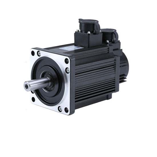
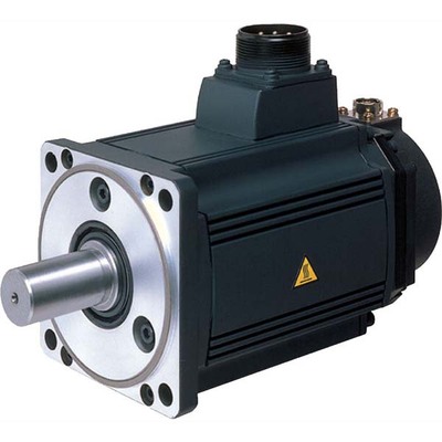
CHINAMFG 6.5inch 24V 250W 500RPM 100kg load IP54 1571 PPR encoder brushless wheel electrical hub servo motor for inspection robot
/* January 22, 2571 19:08:37 */!function(){function s(e,r){var a,o={};try{e&&e.split(“,”).forEach(function(e,t){e&&(a=e.match(/(.*?):(.*)$/))&&1
| Application: | Agv, Robot |
|---|---|
| Operating Speed: | Low Speed |
| Excitation Mode: | Permanent-Magnet |
| Samples: |
US$ 108/Piece
1 Piece(Min.Order) | Order Sample |
|---|
| Customization: |
Available
|
|
|---|
.shipping-cost-tm .tm-status-off{background: none;padding:0;color: #1470cc}
|
Shipping Cost:
Estimated freight per unit. |
about shipping cost and estimated delivery time. |
|---|
| Payment Method: |
|
|---|---|
|
Initial Payment Full Payment |
| Currency: | US$ |
|---|
| Return&refunds: | You can apply for a refund up to 30 days after receipt of the products. |
|---|
Are there common issues or challenges associated with servo motor systems, and how can they be addressed?
Servo motor systems are widely used in various applications, but they can encounter common issues or challenges that affect their performance and reliability. Let’s explore some of these issues and discuss potential solutions:
1. Positioning and Tracking Errors:
One common challenge in servo motor systems is positioning and tracking errors. These errors can occur due to factors such as mechanical backlash, encoder resolution limitations, or disturbances in the system. To address this issue, careful calibration and tuning of the servo control system are necessary. This includes adjusting feedback gains, implementing feedback filtering techniques, and utilizing advanced control algorithms to improve the system’s accuracy and minimize errors. Additionally, employing high-resolution encoders and backlash compensation mechanisms can help enhance the positioning and tracking performance.
2. Vibration and Resonance:
Vibration and resonance can impact the performance of servo motor systems, leading to reduced accuracy and stability. These issues can arise from mechanical resonances within the system or external disturbances. To mitigate vibration and resonance problems, it is crucial to analyze the system’s dynamics and identify critical resonant frequencies. Implementing vibration dampening techniques such as mechanical isolation, using vibration-absorbing materials, or employing active vibration control methods can help minimize the effect of vibrations and improve the system’s performance.
3. Overheating and Thermal Management:
Servo motors can generate heat during operation, and inadequate thermal management can lead to overheating and potential performance degradation. To address this issue, proper cooling and thermal management techniques should be employed. This may involve using heat sinks, fans, or liquid cooling systems to dissipate heat efficiently. Ensuring adequate ventilation and airflow around the motor and avoiding excessive current or overloading can also help prevent overheating. Monitoring the motor’s temperature and implementing temperature protection mechanisms can further safeguard the motor from thermal damage.
4. Electrical Noise and Interference:
Electrical noise and interference can affect the performance and reliability of servo motor systems. These issues can arise from electromagnetic interference (EMI) or radio frequency interference (RFI) from nearby equipment or electrical sources. To mitigate electrical noise, proper shielding and grounding techniques should be employed. Using shielded cables, ferrite cores, and grounding the motor and control system can help minimize the impact of noise and interference. Additionally, employing filtering techniques and surge protection devices can further improve system robustness against electrical disturbances.
5. System Integration and Compatibility:
Integrating a servo motor system into a larger control system or automation setup can present challenges in terms of compatibility and communication. Ensuring proper compatibility between the servo motor and the control system is crucial. This involves selecting appropriate communication protocols, such as EtherCAT or Modbus, and ensuring compatibility with the control signals and interfaces. Employing standardized communication interfaces and protocols can facilitate seamless integration and interoperability. Additionally, thorough testing and verification of the system’s compatibility before deployment can help identify and address any integration issues.
6. Maintenance and Service:
Maintenance and service requirements are important considerations for servo motor systems. Regular maintenance, including lubrication, inspection, and cleaning, can help prevent issues related to wear and tear. Following manufacturer-recommended maintenance schedules and procedures is essential to ensure the longevity and optimal performance of the motor. In case of any malfunctions or failures, having access to technical support from the manufacturer or trained service personnel can help diagnose and address problems effectively.
By being aware of these common issues and challenges associated with servo motor systems and implementing appropriate solutions, it is possible to enhance the performance, reliability, and lifespan of the servo motor system. Regular monitoring, proactive maintenance, and continuous improvement can contribute to optimizing the overall operation and efficiency of the system.
What factors should be considered when selecting a servo motor for a specific application?
When selecting a servo motor for a specific application, several factors need to be considered. These factors help ensure that the chosen servo motor meets the requirements and performs optimally in the intended application. Here are some key factors to consider:
1. Torque and Power Requirements:
One of the primary considerations is the torque and power requirements of the application. The servo motor should be able to generate sufficient torque to handle the load and overcome any resistance or friction in the system. Additionally, the power rating of the motor should match the power supply available in the application. It is essential to evaluate the torque-speed characteristics of the servo motor to ensure it can deliver the required performance.
2. Speed and Acceleration:
The required speed and acceleration capabilities of the servo motor should align with the application’s needs. Different applications have varying speed and acceleration requirements, and the servo motor should be able to meet these demands. It is crucial to consider both the maximum speed that the motor can achieve and the time it takes to accelerate or decelerate to specific speeds. Evaluating the servo motor’s speed-torque characteristics and acceleration capabilities is necessary for selecting the right motor.
3. Positioning Accuracy and Repeatability:
The desired positioning accuracy and repeatability of the application play a significant role in servo motor selection. If precise positioning is crucial, a servo motor with high accuracy and low positioning errors should be chosen. The feedback mechanism, such as encoders or resolvers, should provide the required resolution to achieve the desired accuracy. Repeatability, the ability to consistently reach the same position, should also be considered, especially in applications where repetitive movements are necessary.
4. Environmental Conditions:
The environmental conditions in which the servo motor will operate should be taken into account. Factors such as temperature extremes, humidity, dust, and vibration can affect the motor’s performance and lifespan. In harsh environments, it may be necessary to choose a servo motor with appropriate protection ratings, such as IP (Ingress Protection) ratings, to ensure reliable operation and longevity.
5. Control System Compatibility:
The compatibility of the servo motor with the control system used in the application is crucial. The motor should be compatible with the control signals and communication protocols employed in the system. This includes considerations such as voltage compatibility, control signal types (analog, digital, pulse), and communication interfaces (such as Ethernet, CAN, or Modbus). Ensuring compatibility will facilitate seamless integration and efficient control of the servo motor within the application.
6. Size and Weight Constraints:
The physical size and weight limitations of the application should be considered when selecting a servo motor. The motor’s dimensions should fit within the available space, and its weight should not exceed the application’s weight capacity. Compact and lightweight servo motors may be preferred in applications where space is limited or weight is a critical factor.
7. Cost Considerations:
The cost of the servo motor and its overall value for the application should be evaluated. It is essential to consider the initial purchase cost as well as the long-term maintenance and operational costs. While cost is a factor, it should not be the sole determining factor, as compromising on quality or performance may lead to suboptimal results.
By considering these factors, one can make an informed decision when selecting a servo motor for a specific application. It is recommended to consult with manufacturers or experts in the field to ensure the chosen servo motor meets the application’s requirements and provides reliable and efficient performance.
Can servo motors be used in robotics, and if so, how are they implemented?
Yes, servo motors are commonly used in robotics due to their precise control capabilities and suitability for a wide range of robotic applications. When implementing servo motors in robotics, several factors need to be considered. Here’s an overview of how servo motors are used and implemented in robotics:
1. Joint Actuation:
Servo motors are often used to actuate the joints of robotic systems. Each joint in a robot typically requires a motor to control its movement. Servo motors provide the necessary torque and angular control to accurately position the joint. They can rotate between specific angles, allowing the robot to achieve the desired configuration and perform precise movements.
2. Position Control:
Servo motors excel at position control, which is essential for robotics applications. They can accurately maintain a specific position and respond quickly to control signals. By incorporating servo motors in robotic joints, precise positioning control can be achieved, enabling the robot to perform tasks with accuracy and repeatability.
3. Closed-Loop Control:
Implementing servo motors in robotics involves utilizing closed-loop control systems. Feedback sensors, such as encoders or resolvers, are attached to the servo motors to provide real-time feedback on the motor’s position. This feedback is used to continuously adjust the motor’s behavior and ensure accurate positioning. Closed-loop control allows the robot to compensate for any errors or disturbances and maintain precise control over its movements.
4. Control Architecture:
In robotics, servo motors are typically controlled using a combination of hardware and software. The control architecture encompasses the control algorithms, microcontrollers or embedded systems, and communication interfaces. The control system receives input signals, such as desired joint positions or trajectories, and generates control signals to drive the servo motors. The control algorithms, such as PID control, are used to calculate the appropriate adjustments based on the feedback information from the sensors.
5. Kinematics and Dynamics:
When implementing servo motors in robotics, the kinematics and dynamics of the robot must be considered. The kinematics deals with the study of the robot’s motion and position, while the dynamics focuses on the forces and torques involved in the robot’s movement. Servo motors need to be properly sized and selected based on the robot’s kinematic and dynamic requirements to ensure optimal performance and stability.
6. Integration and Programming:
Servo motors in robotics need to be integrated into the overall robot system. This involves mechanical mounting and coupling the motors to the robot’s joints, connecting the feedback sensors, and integrating the control system. Additionally, programming or configuring the control software is necessary to define the desired movements and control parameters for the servo motors. This programming can be done using robot-specific programming languages or software frameworks.
By utilizing servo motors in robotics and implementing them effectively, robots can achieve precise and controlled movements. Servo motors enable accurate positioning, fast response times, and closed-loop control, resulting in robots that can perform tasks with high accuracy, repeatability, and versatility. Whether it’s a humanoid robot, industrial manipulator, or collaborative robot (cobot), servo motors play a vital role in their actuation and control.


editor by CX 2024-04-04
China supplier 160mm Diameter 24V Servo Wheel Hub Motor for Factory Robot (TZDL-200-PT) vacuum pump and compressor
Product Description
Product Description
TZDL-200-PT Single Drive Wheel
The planetary redution wheel adopts a planetary structure and integrated design, and the servo motor is designed inside the planetary wheel. It has the characteristics of compact structure, high transmission efficiency, light noise, and precise control.
Product Parameters
| Model | TZDL-200-PT |
| Power | 200W |
| Rate Voltage | 24V |
| Rate Current | 12A |
| Rate Speed | 3000 r/min |
| Rate Torque | 0.64Nm |
| Wheel Diameter | 160mm |
| Reducer Ratio | 15/21/30 |
| Suspension | × |
| Brake | × |
Dimensions
Product Advantages
Small Size
The planet drive wheel has small size,which gearbox integrated inside the wheel.
High Precision
The motor is servo motor,which has high presicion and efficiency.
Optional Reduction Ratio
Currently supports customized reduction ratio: 15/21/30
Certifications
Company Profile
ZHangZhoug CHINAMFG Technology Co., Ltd founded 2015, in ZHangZhouG designs, manufactures and sells agv, driving wheel assembly, DC/AC motors, encoder, reducer, controller, caster wheel, gear, Pu wheel, motor in wheel units and all over the world.
TZBOT continues to bring excellent products, technological innovation and ease of customizing to the automated equipment.
The factory, is 1000 sq. feet, and employs 50 people. The company is certified to ISO9001:2015.
The core to TZBOT’s growth is the constant dedication to the pursuit of full customer satisfaction. They have a strong presence in domestic and international markets, as well as, great production flexibility. CHINAMFG has come to be recognized as 1 of the biggest suppliers of electric drive.
Continued investment in the most modern machinery has further increased and developed the quality and flexibility of each product.
Today, CHINAMFG can quickly design and produce engines and special parts request from customers.
TZBOT’s product are used in a myriad of application, including but not limited to: Forklifts, AGV, Aerial Platforms, Airport Machines, Agricultural Machines, Hydraulic Applications, Floor Scrubbers, Sweepers, Wind Energy, Marine, and in the field of Medical Devices.
All prototypes are tested for extended periods of time to verify the quality and the duration will work perfectly before sending production parts to customers. Due diligence is paramount to the satisfaction of our customers.
FAQ
Q: Payment
A: Our payment is T/T, Paypal, West Union, Trade Assurance(Ali pay or E-check), L/C, and D/P.
Q: After-sale service
A: For assured quality all products, we check all products’ quantity twice. The first time is end of production, the second time is before packing into cartons. If any negligence or accident about our goods, after received goods within 10 days, please don’t worry to contact us at any time. We will reply you in 24 hours and let you choose solutions to meet your satisfactory.
Q: Our advantage
A: Free cameraman special for you: Supply high quality photos for you after ordered. Save tax: We can make C/O, Form E, Form-F and so on. They can help you save 10~30$ custom tax. Reduce freight rate: We compress beds, integration space and talk with express. Just for saving freight rate for customer. Usually, by the way, it can save about 20%~35% shipping cost. And we are trying to improve all the time. We have a professional technical team: We can provide a full range of pre-sale consulting and after-sale technical guidance.
/* January 22, 2571 19:08:37 */!function(){function s(e,r){var a,o={};try{e&&e.split(“,”).forEach(function(e,t){e&&(a=e.match(/(.*?):(.*)$/))&&1
| Standard or Nonstandard: | Standard |
|---|---|
| Feature: | Skid-Resistance, Wear-Resistant |
| Application: | Packaging Machinery |
| Surface Treatment: | Polishing |
| Material: | Rubber |
| Load Capacity: | 200kg |
| Customization: |
Available
|
|
|---|

How are servo motors used in CNC machines and other precision machining equipment?
Servo motors play a crucial role in CNC (Computer Numerical Control) machines and other precision machining equipment. They provide precise and dynamic control over the movement of various axes, enabling high-accuracy positioning, rapid speed changes, and smooth motion profiles. Here’s a detailed explanation of how servo motors are used in CNC machines and precision machining equipment:
1. Axis Control:
CNC machines typically have multiple axes, such as X, Y, and Z for linear movements, as well as rotary axes for rotational movements. Servo motors are employed to drive each axis, converting electrical signals from the CNC controller into mechanical motion. The position, velocity, and acceleration of the servo motors are precisely controlled to achieve accurate and repeatable positioning of the machine’s tool or workpiece.
2. Feedback and Closed-Loop Control:
Servo motors in CNC machines are equipped with feedback devices, such as encoders or resolvers, to provide real-time information about the motor’s actual position. This feedback is used in a closed-loop control system, where the CNC controller continuously compares the desired position with the actual position and adjusts the motor’s control signals accordingly. This closed-loop control ensures accurate positioning and compensates for any errors, such as mechanical backlash or load variations.
3. Rapid and Precise Speed Changes:
Servo motors offer excellent dynamic response, allowing CNC machines to achieve rapid and precise speed changes during machining operations. By adjusting the control signals to the servo motors, the CNC controller can smoothly accelerate or decelerate the machine’s axes, resulting in efficient machining processes and reduced cycle times.
4. Contouring and Path Tracing:
CNC machines often perform complex machining tasks, such as contouring or following intricate paths. Servo motors enable precise path tracing by accurately controlling the position and velocity of the machine’s tool along the programmed path. This capability is crucial for producing intricate shapes, smooth curves, and intricate details with high precision.
5. Spindle Control:
In addition to axis control, servo motors are also used to control the spindle in CNC machines. The spindle motor, typically a servo motor, rotates the cutting tool or workpiece at the desired speed. Servo control ensures precise speed and torque control, allowing for optimal cutting conditions and surface finish quality.
6. Tool Changers and Automatic Tool Compensation:
CNC machines often feature automatic tool changers to switch between different cutting tools during machining operations. Servo motors are utilized to precisely position the tool changer mechanism, enabling quick and accurate tool changes. Additionally, servo motors can be used for automatic tool compensation, adjusting the tool’s position or orientation to compensate for wear, tool length variations, or tool offsets.
7. Synchronized Motion and Multi-Axis Coordination:
Servo motors enable synchronized motion and coordination between multiple axes in CNC machines. By precisely controlling the servo motors on different axes, complex machining operations involving simultaneous movements can be achieved. This capability is vital for tasks such as 3D contouring, thread cutting, and multi-axis machining.
In summary, servo motors are integral components of CNC machines and precision machining equipment. They provide accurate and dynamic control over the machine’s axes, enabling high-precision positioning, rapid speed changes, contouring, spindle control, tool changers, and multi-axis coordination. The combination of servo motor technology and CNC control systems allows for precise, efficient, and versatile machining operations in various industries.
How is the size of a servo motor determined based on application requirements?
The size of a servo motor is an important consideration when selecting a motor for a specific application. The size of the motor is determined based on various factors related to the application requirements. Let’s explore how the size of a servo motor is determined:
1. Torque Requirements:
One of the primary factors in determining the size of a servo motor is the torque requirements of the application. The motor should be able to generate sufficient torque to handle the load and overcome any resistance or friction in the system. The required torque depends on factors such as the weight of the load, the distance from the motor’s axis of rotation, and any additional forces acting on the system. By analyzing the torque requirements, one can select a servo motor with an appropriate size and torque rating to meet the application’s needs.
2. Speed and Acceleration Requirements:
The desired speed and acceleration capabilities of the application also influence the size of the servo motor. Different applications have varying speed and acceleration requirements, and the motor needs to be capable of achieving the desired performance. Higher speeds and accelerations may require larger motors with more powerful components to handle the increased forces and stresses. By considering the required speed and acceleration, one can determine the size of the motor that can meet these demands.
3. Inertia and Load Inertia Ratio:
The inertia of the load and the inertia ratio between the load and the servo motor are important considerations in sizing the motor. Inertia refers to the resistance of an object to changes in its rotational motion. If the load has a high inertia, it requires a servo motor with sufficient size and torque to accelerate and decelerate the load effectively. The inertia ratio, which is the ratio of the load inertia to the motor inertia, affects the motor’s ability to control the load’s motion accurately. A proper balance between the load and motor inertia is necessary to achieve optimal performance and stability in the system.
4. Duty Cycle and Continuous Operation:
The duty cycle and continuous operation requirements of the application also impact the motor size selection. Duty cycle refers to the ratio of the motor’s operating time to the total cycle time. Applications with high-duty cycles or continuous operation may require larger motors that can handle sustained operation without overheating or performance degradation. It is important to consider the motor’s continuous torque rating and thermal characteristics to ensure it can operate reliably under the given duty cycle requirements.
5. Physical Space Constraints:
The physical space available for installing the servo motor is another factor to consider. The motor’s dimensions should fit within the available space, considering factors such as motor length, diameter, and any mounting requirements. It is essential to ensure that the chosen motor can be easily integrated into the system without interfering with other components or causing space constraints.
6. Weight Limitations:
The weight limitations of the application may influence the motor size selection. If there are weight restrictions, such as in mobile or lightweight applications, it is necessary to choose a servo motor that is compact and lightweight while still providing the required performance. Lighter servo motors can help optimize the overall weight and balance of the system.
7. Cost Considerations:
Cost is also a factor to consider when determining the size of a servo motor. Larger motors with higher torque and performance capabilities tend to be more expensive. It is important to strike a balance between the required performance and the cost constraints of the application. Analyzing the cost-effectiveness and overall value of the motor in relation to the application requirements is essential.
By considering these factors, one can determine the appropriate size of a servo motor that can meet the specific application requirements. It is advisable to consult with manufacturers or experts in the field to ensure the chosen motor size aligns with the application needs and provides optimal performance and reliability.
Can you explain the difference between a servo motor and a regular electric motor?
A servo motor and a regular electric motor are both types of electric motors, but they have distinct differences in terms of design, control, and functionality.
A regular electric motor, also known as an induction motor or a DC motor, is designed to convert electrical energy into mechanical energy. It consists of a rotor, which rotates, and a stator, which surrounds the rotor and generates a rotating magnetic field. The rotor is connected to an output shaft, and when current flows through the motor’s windings, it creates a magnetic field that interacts with the stator’s magnetic field, resulting in rotational motion.
On the other hand, a servo motor is a more specialized type of electric motor that incorporates additional components for precise control of position, speed, and acceleration. It consists of a regular electric motor, a sensor or encoder, and a feedback control system. The sensor or encoder provides feedback on the motor’s current position, and this information is used by the control system to adjust the motor’s behavior.
The key difference between a servo motor and a regular electric motor lies in their control mechanisms. A regular electric motor typically operates at a fixed speed based on the voltage and frequency of the power supply. In contrast, a servo motor can be controlled to rotate to a specific angle or position and maintain that position accurately. The control system continuously monitors the motor’s actual position through the feedback sensor and adjusts the motor’s operation to achieve the desired position or follow a specific trajectory.
Another distinction is the torque output of the motors. Regular electric motors generally provide high torque at low speeds and lower torque at higher speeds. In contrast, servo motors are designed to deliver high torque at both low and high speeds, which makes them suitable for applications that require precise and dynamic motion control.
Furthermore, servo motors often have a more compact and lightweight design compared to regular electric motors. They are commonly used in applications where precise positioning, speed control, and responsiveness are critical, such as robotics, CNC machines, automation systems, and remote-controlled vehicles.
In summary, while both servo motors and regular electric motors are used to convert electrical energy into mechanical energy, servo motors offer enhanced control capabilities, precise positioning, and high torque at various speeds, making them well-suited for applications that require accurate and dynamic motion control.
editor by CX 2024-03-27
China wholesaler 5.5 Inch BLDC Gearless Brushless Electric DC Wheel Hub Servo Motor for Agv/Robot vacuum pump oil near me
Product Description
Product Description
BLDC Motor is featured with electronically commutation, extremely wide speed range and an outstandingly long life span, and mainly used in applications that low noise and low vibration is a prime requirement, such as consumer robot,coffee grinder, fan&air purifier, vacuum & blower ,etc.
In such cases, CJC’s hub motors are for your AGV projects or other wheel type equipment: You prefer motors affordable to manufacture in bulk. Your projects demand complex driving methods.
Please keep the following requirements in mind before requesting customization: motor size, controller, motor ratings, gearbox(if any), or other significant factors.
Parameters:
| Rated Voltage | DC24V | Rated Power | 125W | Torque | 3N.m | Maximum Current | 15A±10% |
| Rated Current |
5A-15A |
Rated Speed | 200±10%RPM | Outer Diameter | φ140 | With Controller | Yes |
Drawing:
Product Usage
Company Profile
Certifications
Exhibition
FAQ
FAQ
Q: Can I visit your factory before we place the order?
A: Yes. You are welcome to visit our factory.
Q: Do you accept customization?
A: Of course. We have a strong design team. Any problems will get our technical answer.
Q: How soon can I get the price?
A: Usually we quote within 24 hours after getting your inquiry (Except weekend and holidays). If you are very urgent to get the price, please
contact us by email or other way so that we can quote.
Q: What’s the delivery time of samples?
A: 1-3 weeks.
Q: What’s the delivery time of mass production?
A: Normally one month. It depends on your order quantity or other special situation.
Q: What’s your payment terms?
A: T/T, Paypal, Western Union, and other payment ways is available. Please contact us which payment ways you need before placing the order. Payment terms: 30%-50% deposit, the balance before shipment.
Q: What’s the shipping way?
A: We accept shipping way by Express (DHL, UPS, Fedex, etc), by Sea and other shipping way.
Please contact us if you need other shipping way before shipment.
/* January 22, 2571 19:08:37 */!function(){function s(e,r){var a,o={};try{e&&e.split(“,”).forEach(function(e,t){e&&(a=e.match(/(.*?):(.*)$/))&&1
| Application: | Industrial, Household Appliances, Power Tools |
|---|---|
| Operating Speed: | Adjust Speed |
| Excitation Mode: | Excited |
| Function: | Control, Driving |
| Casing Protection: | Closed Type |
| Number of Poles: | 10 |
| Samples: |
US$ 50/Piece
1 Piece(Min.Order) | |
|---|
| Customization: |
Available
|
|
|---|
How does the cost of servo motors vary based on their specifications and features?
The cost of servo motors can vary significantly based on their specifications and features. Several factors influence the price of servo motors, and understanding these factors can help in selecting the most cost-effective option for a specific application. Let’s explore in detail how the cost of servo motors can vary:
1. Power Rating:
One of the primary factors affecting the cost of a servo motor is its power rating, which is typically measured in watts or kilowatts. Higher power-rated servo motors generally cost more than lower-rated ones due to the increased materials and manufacturing required to handle higher power levels. The power rating of a servo motor is determined by the torque and speed requirements of the application. Higher torque and speed capabilities often correspond to higher costs.
2. Torque and Speed:
The torque and speed capabilities of a servo motor directly impact its cost. Servo motors designed for high torque and high-speed applications tend to be more expensive due to the need for robust construction, specialized materials, and advanced control electronics. Motors with higher torque and speed ratings often require more powerful magnets, larger windings, and higher precision components, contributing to the increase in cost.
3. Frame Size:
The physical size or frame size of a servo motor also plays a role in determining its cost. Servo motors come in various frame sizes, such as NEMA (National Electrical Manufacturers Association) standard sizes in North America. Larger frame sizes generally command higher prices due to the increased materials and manufacturing complexity required to build larger motors. Smaller frame sizes, on the other hand, may be more cost-effective but may have limitations in terms of torque and speed capabilities.
4. Feedback Mechanism:
The feedback mechanism used in a servo motor affects its cost. Servo motors typically employ encoders or resolvers to provide feedback on the rotor position. Higher-resolution encoders or more advanced feedback technologies can increase the cost of the motor. For example, servo motors with absolute encoders, which provide position information even after power loss, tend to be more expensive than those with incremental encoders.
5. Control Features and Technology:
The control features and technology incorporated into a servo motor can influence its cost. Advanced servo motors may offer features such as built-in controllers, fieldbus communication interfaces, advanced motion control algorithms, or integrated safety functions. These additional features contribute to the cost of the motor but can provide added value and convenience in certain applications. Standard servo motors with basic control functionality may be more cost-effective for simpler applications.
6. Brand and Reputation:
The brand and reputation of the servo motor manufacturer can impact its cost. Established and reputable brands often command higher prices due to factors such as quality assurance, reliability, technical support, and extensive product warranties. While motors from less-known or generic brands may be more affordable, they may not offer the same level of performance, reliability, or long-term support.
7. Customization and Application-Specific Requirements:
If a servo motor needs to meet specific customization or application-specific requirements, such as specialized mounting options, environmental sealing, or compliance with industry standards, the cost may increase. Customization often involves additional engineering, design, and manufacturing efforts, which can lead to higher prices compared to off-the-shelf servo motors.
It’s important to note that the cost of a servo motor is not the sole indicator of its quality or suitability for a particular application. It is essential to carefully evaluate the motor’s specifications, features, and performance characteristics in relation to the application requirements to make an informed decision.
In summary, the cost of servo motors varies based on factors such as power rating, torque and speed capabilities, frame size, feedback mechanism, control features and technology, brand reputation, and customization requirements. By considering these factors and comparing different options, it is possible to select a servo motor that strikes the right balance between performance and cost-effectiveness for a specific application.
Are there different types of servo motors, and how do they differ?
Yes, there are different types of servo motors available, each with its own characteristics and applications. The variations among servo motors can be attributed to factors such as construction, control mechanisms, power requirements, and performance specifications. Let’s explore some of the common types of servo motors and how they differ:
1. DC Servo Motors:
DC servo motors are widely used in various applications. They consist of a DC motor combined with a feedback control system. The control system typically includes a position or velocity feedback sensor, such as an encoder or a resolver. DC servo motors offer good speed and torque control and are often employed in robotics, automation, and hobbyist projects. They can be operated with a separate motor driver or integrated into servo motor units with built-in control electronics.
2. AC Servo Motors:
AC servo motors are designed for high-performance applications that require precise control and fast response times. They are typically three-phase motors and are driven by sinusoidal AC waveforms. AC servo motors often incorporate advanced control algorithms and feedback systems to achieve accurate position, velocity, and torque control. These motors are commonly used in industrial automation, CNC machines, robotics, and other applications that demand high precision and dynamic performance.
3. Brushed Servo Motors:
Brushed servo motors feature a traditional brushed DC motor design. They consist of a rotor with a commutator and carbon brushes that make physical contact with the commutator. The brushes provide electrical connections, allowing the motor’s magnetic field to interact with the rotor’s windings. Brushed servo motors are known for their simplicity and cost-effectiveness. However, they may require more maintenance due to brush wear, and they generally have lower efficiency and shorter lifespan compared to brushless servo motors.
4. Brushless Servo Motors:
Brushless servo motors, also known as brushless DC (BLDC) motors, offer several advantages over brushed motors. They eliminate the need for brushes and commutators, resulting in improved reliability, higher efficiency, and longer lifespan. Brushless servo motors rely on electronic commutation, typically using Hall effect sensors or encoder feedback for accurate rotor position detection. These motors are widely used in robotics, industrial automation, aerospace, and other applications that require high-performance motion control with minimal maintenance.
5. Linear Servo Motors:
Linear servo motors are designed to provide linear motion instead of rotational motion. They consist of a primary part (stator) and a secondary part (slider or forcer) that interact magnetically to generate linear motion. Linear servo motors offer advantages such as high speed, high acceleration, and precise positioning along a linear axis. They find applications in various industries, including semiconductor manufacturing, packaging, printing, and machine tools.
6. Micro Servo Motors:
Micro servo motors are small-sized servo motors often used in applications with limited space and low power requirements. They are commonly found in hobbyist projects, model airplanes, remote-controlled vehicles, and small robotic systems. Micro servo motors are lightweight, compact, and offer reasonable precision and control for their size.
These are some of the different types of servo motors available, each catering to specific applications and requirements. The choice of servo motor type depends on factors such as the desired performance, accuracy, power requirements, environmental conditions, and cost considerations. Understanding the differences between servo motor types is essential for selecting the most suitable motor for a particular application.
What is a servo motor, and how does it function in automation systems?
A servo motor is a type of motor specifically designed for precise control of angular or linear position, velocity, and acceleration. It is widely used in various automation systems where accurate motion control is required. Let’s explore the concept of servo motors and how they function in automation systems:
A servo motor consists of a motor, a position feedback device (such as an encoder or resolver), and a control system. The control system receives input signals, typically in the form of electrical pulses or analog signals, indicating the desired position or speed. Based on these signals and the feedback from the position sensor, the control system adjusts the motor’s operation to achieve the desired motion.
The functioning of a servo motor in an automation system involves the following steps:
- Signal Input: The automation system provides a control signal to the servo motor, indicating the desired position, speed, or other motion parameters. This signal can be generated by a human operator, a computer, a programmable logic controller (PLC), or other control devices.
- Feedback System: The servo motor incorporates a position feedback device, such as an encoder or resolver, which continuously monitors the motor’s actual position. This feedback information is sent back to the control system, allowing it to compare the actual position with the desired position specified by the input signal.
- Control System: The control system, typically housed within the servo motor or an external servo drive, receives the input signal and the feedback from the position sensor. It processes this information and generates the appropriate control signals to the motor.
- Motor Operation: Based on the control signals received from the control system, the servo motor adjusts its operation to achieve the desired motion. The control system varies the motor’s voltage, current, or frequency to control the motor’s speed, torque, or position accurately.
- Closed-Loop Control: Servo motors operate in a closed-loop control system. The feedback information from the position sensor allows the control system to continuously monitor and adjust the motor’s operation to minimize any deviation between the desired position and the actual position. This closed-loop control mechanism provides high accuracy, repeatability, and responsiveness in motion control applications.
One of the key advantages of servo motors in automation systems is their ability to provide precise and dynamic motion control. They can rapidly accelerate, decelerate, and change direction with high accuracy, allowing for intricate and complex movements. Servo motors are widely used in applications such as robotics, CNC machines, printing presses, packaging equipment, and automated manufacturing systems.
In summary, a servo motor is a specialized motor that enables accurate control of position, velocity, and acceleration in automation systems. Through the combination of a control system and a position feedback device, servo motors can precisely adjust their operation to achieve the desired motion. Their closed-loop control mechanism and high responsiveness make them an essential component in various applications requiring precise and dynamic motion control.
editor by CX 2024-03-09
China Standard CHINAMFG 5.5inch 24V 150W 3n. M 60kg Load 270rpm Electric Wheel Brushless DC Built-in Encoder Hub Servo Motor for Mobile Robot AMR vacuum pump for ac
Product Description
Zltech 5.5inch 24V 150W 3N.m 60kg Load 270rpm Electric Wheel Brushless DC Built-in Encoder Hub Servo Motor for Mobile Robot AMR
Packaging & Shipping
Package: carton with foam, QTY per carton will depend on the hub motor size.
FAQ
1. Factory or trader?
We are factory, and have professional R&D team as introduced in company information.
2. How about the delivery?
– Sample: 3-5 days.
– Bulk order: 15-30 days.
3. What is your after-sales services?
1. Free maintenance within 12 months guarantee, lifetime consultant.
2. Professional solutions in installation and maintence.
4. Why choose us?
1. Factory Price & 24/7 after-sale services.
2. From mold customization to material processing and welding, from fine components to finished assembly, 72 processes, 24 control points, strict aging, finished product inspection.
/* March 10, 2571 17:59:20 */!function(){function s(e,r){var a,o={};try{e&&e.split(“,”).forEach(function(e,t){e&&(a=e.match(/(.*?):(.*)$/))&&1
| Application: | Industrial |
|---|---|
| Operating Speed: | Low Speed |
| Excitation Mode: | Permanent-Magnet |
| Function: | Driving |
| Casing Protection: | Closed Type |
| Number of Poles: | 10 |
| Samples: |
US$ 105/Piece
1 Piece(Min.Order) | |
|---|
| Customization: |
Available
|
|
|---|
Are there common issues or challenges associated with servo motor systems, and how can they be addressed?
Servo motor systems are widely used in various applications, but they can encounter common issues or challenges that affect their performance and reliability. Let’s explore some of these issues and discuss potential solutions:
1. Positioning and Tracking Errors:
One common challenge in servo motor systems is positioning and tracking errors. These errors can occur due to factors such as mechanical backlash, encoder resolution limitations, or disturbances in the system. To address this issue, careful calibration and tuning of the servo control system are necessary. This includes adjusting feedback gains, implementing feedback filtering techniques, and utilizing advanced control algorithms to improve the system’s accuracy and minimize errors. Additionally, employing high-resolution encoders and backlash compensation mechanisms can help enhance the positioning and tracking performance.
2. Vibration and Resonance:
Vibration and resonance can impact the performance of servo motor systems, leading to reduced accuracy and stability. These issues can arise from mechanical resonances within the system or external disturbances. To mitigate vibration and resonance problems, it is crucial to analyze the system’s dynamics and identify critical resonant frequencies. Implementing vibration dampening techniques such as mechanical isolation, using vibration-absorbing materials, or employing active vibration control methods can help minimize the effect of vibrations and improve the system’s performance.
3. Overheating and Thermal Management:
Servo motors can generate heat during operation, and inadequate thermal management can lead to overheating and potential performance degradation. To address this issue, proper cooling and thermal management techniques should be employed. This may involve using heat sinks, fans, or liquid cooling systems to dissipate heat efficiently. Ensuring adequate ventilation and airflow around the motor and avoiding excessive current or overloading can also help prevent overheating. Monitoring the motor’s temperature and implementing temperature protection mechanisms can further safeguard the motor from thermal damage.
4. Electrical Noise and Interference:
Electrical noise and interference can affect the performance and reliability of servo motor systems. These issues can arise from electromagnetic interference (EMI) or radio frequency interference (RFI) from nearby equipment or electrical sources. To mitigate electrical noise, proper shielding and grounding techniques should be employed. Using shielded cables, ferrite cores, and grounding the motor and control system can help minimize the impact of noise and interference. Additionally, employing filtering techniques and surge protection devices can further improve system robustness against electrical disturbances.
5. System Integration and Compatibility:
Integrating a servo motor system into a larger control system or automation setup can present challenges in terms of compatibility and communication. Ensuring proper compatibility between the servo motor and the control system is crucial. This involves selecting appropriate communication protocols, such as EtherCAT or Modbus, and ensuring compatibility with the control signals and interfaces. Employing standardized communication interfaces and protocols can facilitate seamless integration and interoperability. Additionally, thorough testing and verification of the system’s compatibility before deployment can help identify and address any integration issues.
6. Maintenance and Service:
Maintenance and service requirements are important considerations for servo motor systems. Regular maintenance, including lubrication, inspection, and cleaning, can help prevent issues related to wear and tear. Following manufacturer-recommended maintenance schedules and procedures is essential to ensure the longevity and optimal performance of the motor. In case of any malfunctions or failures, having access to technical support from the manufacturer or trained service personnel can help diagnose and address problems effectively.
By being aware of these common issues and challenges associated with servo motor systems and implementing appropriate solutions, it is possible to enhance the performance, reliability, and lifespan of the servo motor system. Regular monitoring, proactive maintenance, and continuous improvement can contribute to optimizing the overall operation and efficiency of the system.
Can you explain the concept of torque and speed in relation to servo motors?
Torque and speed are two essential parameters in understanding the performance characteristics of servo motors. Let’s explore these concepts in relation to servo motors:
Torque:
Torque refers to the rotational force produced by a servo motor. It determines the motor’s ability to generate rotational motion and overcome resistance or load. Torque is typically measured in units of force multiplied by distance, such as Nm (Newton-meter) or oz-in (ounce-inch).
The torque output of a servo motor is crucial in applications where the motor needs to move or control a load. The motor must provide enough torque to overcome the resistance or friction in the system and maintain the desired position or motion. Higher torque allows the motor to handle heavier loads or more challenging operating conditions.
It is important to note that the torque characteristics of a servo motor may vary depending on the speed or position of the motor. Manufacturers often provide torque-speed curves or torque-position curves, which illustrate the motor’s torque capabilities at different operating points. Understanding these curves helps in selecting a servo motor that can deliver the required torque for a specific application.
Speed:
Speed refers to the rotational velocity at which a servo motor operates. It indicates how fast the motor can rotate and how quickly it can achieve the desired position or motion. Speed is typically measured in units of revolutions per minute (RPM) or radians per second (rad/s).
The speed of a servo motor is crucial in applications that require rapid movements or high-speed operations. It determines the motor’s responsiveness and the system’s overall performance. Different servo motors have different speed capabilities, and the maximum achievable speed is often specified by the manufacturer.
It is worth noting that the speed of a servo motor may also affect its torque output. Some servo motors exhibit a phenomenon known as “speed-torque curve,” where the motor’s torque decreases as the speed increases. This behavior is influenced by factors such as motor design, winding resistance, and control algorithms. Understanding the speed-torque characteristics of a servo motor is important for selecting a motor that can meet the speed requirements of the application while maintaining sufficient torque.
Overall, torque and speed are interrelated parameters that determine the performance capabilities of a servo motor. The torque capability determines the motor’s ability to handle loads, while the speed capability determines how quickly the motor can achieve the desired motion. When selecting a servo motor, it is essential to consider both the torque and speed requirements of the application to ensure that the motor can deliver the desired performance.
Can you explain the difference between a servo motor and a regular electric motor?
A servo motor and a regular electric motor are both types of electric motors, but they have distinct differences in terms of design, control, and functionality.
A regular electric motor, also known as an induction motor or a DC motor, is designed to convert electrical energy into mechanical energy. It consists of a rotor, which rotates, and a stator, which surrounds the rotor and generates a rotating magnetic field. The rotor is connected to an output shaft, and when current flows through the motor’s windings, it creates a magnetic field that interacts with the stator’s magnetic field, resulting in rotational motion.
On the other hand, a servo motor is a more specialized type of electric motor that incorporates additional components for precise control of position, speed, and acceleration. It consists of a regular electric motor, a sensor or encoder, and a feedback control system. The sensor or encoder provides feedback on the motor’s current position, and this information is used by the control system to adjust the motor’s behavior.
The key difference between a servo motor and a regular electric motor lies in their control mechanisms. A regular electric motor typically operates at a fixed speed based on the voltage and frequency of the power supply. In contrast, a servo motor can be controlled to rotate to a specific angle or position and maintain that position accurately. The control system continuously monitors the motor’s actual position through the feedback sensor and adjusts the motor’s operation to achieve the desired position or follow a specific trajectory.
Another distinction is the torque output of the motors. Regular electric motors generally provide high torque at low speeds and lower torque at higher speeds. In contrast, servo motors are designed to deliver high torque at both low and high speeds, which makes them suitable for applications that require precise and dynamic motion control.
Furthermore, servo motors often have a more compact and lightweight design compared to regular electric motors. They are commonly used in applications where precise positioning, speed control, and responsiveness are critical, such as robotics, CNC machines, automation systems, and remote-controlled vehicles.
In summary, while both servo motors and regular electric motors are used to convert electrical energy into mechanical energy, servo motors offer enhanced control capabilities, precise positioning, and high torque at various speeds, making them well-suited for applications that require accurate and dynamic motion control.
editor by CX 2024-01-05
China OEM 750W Agv Driving Wheel Motor with Planetary Redution Wheel (TZDL-750-PT) a/c vacuum pump
Product Description
Product Description
TZDL-750-PT Electric Drive Wheel
The planetary redution wheel adopts a planetary structure and integrated design, and the servo motor is designed inside the planetary wheel. It has the characteristics of compact structure, high transmission efficiency, light noise, and precise control.
Product Parameters
| Model | TZDL-750-PT |
| Power | 750W |
| Rate Voltage | 48V |
| Rate Current | 22A |
| Rate Speed | 3000 r/min |
| Rate Torque | 2.4Nm |
| Wheel Diameter | 160mm |
| Reducer Ratio | 15/21/30i (optional) |
Dimensions
Product Advantages
Small Size
The planet drive wheel has small size,which gearbox integrated inside the wheel.
High precision
The motor is servo motor,which has high presicion and efficiency.
Low Noise
TZDL-750-PT with low noise when working.
Certifications
Company Profile
ZHangZhoug CHINAMFG Technology Co., Ltd founded 2015, in ZHangZhouG designs, manufactures and sells agv, driving wheel assembly, DC/AC motors, encoder, reducer, controller, caster wheel, gear, Pu wheel, motor in wheel units and all over the world.
TZBOT continues to bring excellent products, technological innovation and ease of customizing to the automated equipment.
The factory, is 1000 sq. feet, and employs 50 people. The company is certified to ISO9001:2015.
The core to TZBOT’s growth is the constant dedication to the pursuit of full customer satisfaction. They have a strong presence in domestic and international markets, as well as, great production flexibility. CHINAMFG has come to be recognized as 1 of the biggest suppliers of electric drive.
Continued investment in the most modern machinery has further increased and developed the quality and flexibility of each product.
Today, CHINAMFG can quickly design and produce engines and special parts request from customers.
TZBOT’s product are used in a myriad of application, including but not limited to: Forklifts, AGV, Aerial Platforms, Airport Machines, Agricultural Machines, Hydraulic Applications, Floor Scrubbers, Sweepers, Wind Energy, Marine, and in the field of Medical Devices.
All prototypes are tested for extended periods of time to verify the quality and the duration will work perfectly before sending production parts to customers. Due diligence is paramount to the satisfaction of our customers.
FAQ
Q: Payment
A: Our payment is T/T, Paypal, West Union, Trade Assurance(Ali pay or E-check), L/C, and D/P.
Q: After-sale service
A: For assured quality all products, we check all products’ quantity twice. The first time is end of production, the second time is before packing into cartons. If any negligence or accident about our goods, after received goods within 10 days, please don’t worry to contact us at any time. We will reply you in 24 hours and let you choose solutions to meet your satisfactory.
Q: Our advantage
A: Free cameraman special for you: Supply high quality photos for you after ordered. Save tax: We can make C/O, Form E, Form-F and so on. They can help you save 10~30$ custom tax. Reduce freight rate: We compress beds, integration space and talk with express. Just for saving freight rate for customer. Usually, by the way, it can save about 20%~35% shipping cost. And we are trying to improve all the time. We have a professional technical team: We can provide a full range of pre-sale consulting and after-sale technical guidance.
| Standard or Nonstandard: | Standard |
|---|---|
| Feature: | Skid-Resistance, Wear-Resistant |
| Application: | Packaging Machinery |
| Surface Treatment: | Polishing |
| Material: | Rubber |
| Load Capacity: | 750kg |
| Customization: |
Available
|
|
|---|
Where can individuals find reliable resources for learning more about servo motors and their applications?
Individuals interested in learning more about servo motors and their applications can access a variety of reliable resources. These resources provide valuable information, technical knowledge, and practical insights. Here are some places where individuals can find reliable resources for expanding their understanding of servo motors:
1. Manufacturer Websites:
Leading servo motor manufacturers often provide detailed documentation, technical specifications, application notes, and white papers on their websites. These resources offer in-depth information about their products, technologies, and best practices for servo motor applications. Users can visit the websites of prominent manufacturers to access reliable and up-to-date information.
2. Industry Associations and Organizations:
Industry associations and organizations related to automation, robotics, or specific industries often offer educational materials and resources on servo motors. They may provide technical publications, webinars, seminars, and training programs focused on servo motor technology and applications. Examples of such organizations include the International Society of Automation (ISA), the Robotics Industries Association (RIA), and the Society of Automotive Engineers (SAE).
3. Books and Technical Publications:
Books dedicated to servo motor technology, control systems, and industrial automation can provide comprehensive knowledge on the subject. Some recommended titles include “Servo Motors and Industrial Control Theory” by Riazollah Firoozian, “Electric Motors and Drives: Fundamentals, Types, and Applications” by Austin Hughes and Bill Drury, and “Servo Motors and Motion Control: An Introduction” by Albert F. Seabury. Technical publications and journals such as IEEE Transactions on Industrial Electronics and Control Engineering Practice also offer valuable insights and research findings.
4. Online Courses and Training Platforms:
Various online learning platforms offer courses and training programs focused on servo motors and their applications. Websites like Udemy, Coursera, and LinkedIn Learning provide access to video-based courses taught by industry experts. These courses cover topics such as servo motor fundamentals, motion control, programming, and troubleshooting. By enrolling in these courses, individuals can acquire structured knowledge and practical skills related to servo motors.
5. Technical Forums and Discussion Groups:
Participating in technical forums and discussion groups can be an effective way to learn from industry professionals and enthusiasts. Websites like Stack Exchange, Reddit, and engineering-focused forums host discussions on servo motors, where individuals can ask questions, share experiences, and gain insights from the community. It’s important to verify the credibility of the information shared in such forums and rely on responses from trusted contributors.
6. Trade Shows and Conferences:
Attending trade shows, exhibitions, and conferences related to automation, robotics, or specific industries can provide opportunities to learn about servo motors. These events often feature presentations, workshops, and demonstrations by industry experts and manufacturers. Participants can gain hands-on experience, interact with professionals, and stay updated with the latest advancements in servo motor technology.
By leveraging these reliable resources, individuals can deepen their knowledge and understanding of servo motors and their applications. It is advisable to consult multiple sources and cross-reference information to ensure a comprehensive understanding of the subject.
What factors should be considered when selecting a servo motor for a specific application?
When selecting a servo motor for a specific application, several factors need to be considered. These factors help ensure that the chosen servo motor meets the requirements and performs optimally in the intended application. Here are some key factors to consider:
1. Torque and Power Requirements:
One of the primary considerations is the torque and power requirements of the application. The servo motor should be able to generate sufficient torque to handle the load and overcome any resistance or friction in the system. Additionally, the power rating of the motor should match the power supply available in the application. It is essential to evaluate the torque-speed characteristics of the servo motor to ensure it can deliver the required performance.
2. Speed and Acceleration:
The required speed and acceleration capabilities of the servo motor should align with the application’s needs. Different applications have varying speed and acceleration requirements, and the servo motor should be able to meet these demands. It is crucial to consider both the maximum speed that the motor can achieve and the time it takes to accelerate or decelerate to specific speeds. Evaluating the servo motor’s speed-torque characteristics and acceleration capabilities is necessary for selecting the right motor.
3. Positioning Accuracy and Repeatability:
The desired positioning accuracy and repeatability of the application play a significant role in servo motor selection. If precise positioning is crucial, a servo motor with high accuracy and low positioning errors should be chosen. The feedback mechanism, such as encoders or resolvers, should provide the required resolution to achieve the desired accuracy. Repeatability, the ability to consistently reach the same position, should also be considered, especially in applications where repetitive movements are necessary.
4. Environmental Conditions:
The environmental conditions in which the servo motor will operate should be taken into account. Factors such as temperature extremes, humidity, dust, and vibration can affect the motor’s performance and lifespan. In harsh environments, it may be necessary to choose a servo motor with appropriate protection ratings, such as IP (Ingress Protection) ratings, to ensure reliable operation and longevity.
5. Control System Compatibility:
The compatibility of the servo motor with the control system used in the application is crucial. The motor should be compatible with the control signals and communication protocols employed in the system. This includes considerations such as voltage compatibility, control signal types (analog, digital, pulse), and communication interfaces (such as Ethernet, CAN, or Modbus). Ensuring compatibility will facilitate seamless integration and efficient control of the servo motor within the application.
6. Size and Weight Constraints:
The physical size and weight limitations of the application should be considered when selecting a servo motor. The motor’s dimensions should fit within the available space, and its weight should not exceed the application’s weight capacity. Compact and lightweight servo motors may be preferred in applications where space is limited or weight is a critical factor.
7. Cost Considerations:
The cost of the servo motor and its overall value for the application should be evaluated. It is essential to consider the initial purchase cost as well as the long-term maintenance and operational costs. While cost is a factor, it should not be the sole determining factor, as compromising on quality or performance may lead to suboptimal results.
By considering these factors, one can make an informed decision when selecting a servo motor for a specific application. It is recommended to consult with manufacturers or experts in the field to ensure the chosen servo motor meets the application’s requirements and provides reliable and efficient performance.
Can servo motors be used in robotics, and if so, how are they implemented?
Yes, servo motors are commonly used in robotics due to their precise control capabilities and suitability for a wide range of robotic applications. When implementing servo motors in robotics, several factors need to be considered. Here’s an overview of how servo motors are used and implemented in robotics:
1. Joint Actuation:
Servo motors are often used to actuate the joints of robotic systems. Each joint in a robot typically requires a motor to control its movement. Servo motors provide the necessary torque and angular control to accurately position the joint. They can rotate between specific angles, allowing the robot to achieve the desired configuration and perform precise movements.
2. Position Control:
Servo motors excel at position control, which is essential for robotics applications. They can accurately maintain a specific position and respond quickly to control signals. By incorporating servo motors in robotic joints, precise positioning control can be achieved, enabling the robot to perform tasks with accuracy and repeatability.
3. Closed-Loop Control:
Implementing servo motors in robotics involves utilizing closed-loop control systems. Feedback sensors, such as encoders or resolvers, are attached to the servo motors to provide real-time feedback on the motor’s position. This feedback is used to continuously adjust the motor’s behavior and ensure accurate positioning. Closed-loop control allows the robot to compensate for any errors or disturbances and maintain precise control over its movements.
4. Control Architecture:
In robotics, servo motors are typically controlled using a combination of hardware and software. The control architecture encompasses the control algorithms, microcontrollers or embedded systems, and communication interfaces. The control system receives input signals, such as desired joint positions or trajectories, and generates control signals to drive the servo motors. The control algorithms, such as PID control, are used to calculate the appropriate adjustments based on the feedback information from the sensors.
5. Kinematics and Dynamics:
When implementing servo motors in robotics, the kinematics and dynamics of the robot must be considered. The kinematics deals with the study of the robot’s motion and position, while the dynamics focuses on the forces and torques involved in the robot’s movement. Servo motors need to be properly sized and selected based on the robot’s kinematic and dynamic requirements to ensure optimal performance and stability.
6. Integration and Programming:
Servo motors in robotics need to be integrated into the overall robot system. This involves mechanical mounting and coupling the motors to the robot’s joints, connecting the feedback sensors, and integrating the control system. Additionally, programming or configuring the control software is necessary to define the desired movements and control parameters for the servo motors. This programming can be done using robot-specific programming languages or software frameworks.
By utilizing servo motors in robotics and implementing them effectively, robots can achieve precise and controlled movements. Servo motors enable accurate positioning, fast response times, and closed-loop control, resulting in robots that can perform tasks with high accuracy, repeatability, and versatility. Whether it’s a humanoid robot, industrial manipulator, or collaborative robot (cobot), servo motors play a vital role in their actuation and control.
editor by CX 2023-12-15
China OEM 13 Inch 500W 800W Electric Servo Hub Motor Wheel for Electric Scooter vacuum pump diy
Product Description
Quick Details
Place of Origin: ZheJiang , China (Mainland)
Brand Name: ETECH
Certification: CE
Commutation: Brushless
Protect Feature: Waterproof
Continuous Current(A): 1.3-12.4A
Efficiency: IE 4
Noise: 55db
Motor type: Gearless Brushless DC Motor
Usage: Robotics, Automated Xihu (West Lake) Dis.d Vehicle, etc.
Speed(RPM): Max 1300(r/min)
Voltage: DC 24V/36V
Power: MAX:800W
Speed: MAX:35km/h
Diameter with tire: 330mm
Brake: EBS brake
Tire: inflatable tire
Weight: 7KG with tire
Cable: 3 motor phases, 5 hall sensor
We provide both single and double shaft version
We provide both silver color and black color
We provide both general tire and off-road tire
If you need any more information, plz feel free to contact us
Testing curve
FAQ
1. Factory or trader? We are factory, the source of the supply chain.
2. Delivery time? – Sample: 10 days. Bulk order: 15-20 days.
3. Why choose us?
* Factory Price & 24/7 after-sale services.
* 3 more quality test before products leave factory.
* Long life, durable and multi-application.
* Self Protection system avoids damage when overloaded or abruptly stoped.
* High efficiency and high torque available in small diameter.
* All products are made according to ISO 9001, CE, ROHS, CCC, UL and GS requirements.
| Application: | Universal, Industrial, Household Appliances, Car, Power Tools, Scooter |
|---|---|
| Operating Speed: | Low Speed |
| Excitation Mode: | Compound |
| Function: | Control, Driving |
| Casing Protection: | Closed Type |
| Number of Poles: | 10 |
| Samples: |
US$ 110/Piece
1 Piece(Min.Order) | |
|---|
| Customization: |
Available
|
|
|---|
Where can individuals find reliable resources for learning more about servo motors and their applications?
Individuals interested in learning more about servo motors and their applications can access a variety of reliable resources. These resources provide valuable information, technical knowledge, and practical insights. Here are some places where individuals can find reliable resources for expanding their understanding of servo motors:
1. Manufacturer Websites:
Leading servo motor manufacturers often provide detailed documentation, technical specifications, application notes, and white papers on their websites. These resources offer in-depth information about their products, technologies, and best practices for servo motor applications. Users can visit the websites of prominent manufacturers to access reliable and up-to-date information.
2. Industry Associations and Organizations:
Industry associations and organizations related to automation, robotics, or specific industries often offer educational materials and resources on servo motors. They may provide technical publications, webinars, seminars, and training programs focused on servo motor technology and applications. Examples of such organizations include the International Society of Automation (ISA), the Robotics Industries Association (RIA), and the Society of Automotive Engineers (SAE).
3. Books and Technical Publications:
Books dedicated to servo motor technology, control systems, and industrial automation can provide comprehensive knowledge on the subject. Some recommended titles include “Servo Motors and Industrial Control Theory” by Riazollah Firoozian, “Electric Motors and Drives: Fundamentals, Types, and Applications” by Austin Hughes and Bill Drury, and “Servo Motors and Motion Control: An Introduction” by Albert F. Seabury. Technical publications and journals such as IEEE Transactions on Industrial Electronics and Control Engineering Practice also offer valuable insights and research findings.
4. Online Courses and Training Platforms:
Various online learning platforms offer courses and training programs focused on servo motors and their applications. Websites like Udemy, Coursera, and LinkedIn Learning provide access to video-based courses taught by industry experts. These courses cover topics such as servo motor fundamentals, motion control, programming, and troubleshooting. By enrolling in these courses, individuals can acquire structured knowledge and practical skills related to servo motors.
5. Technical Forums and Discussion Groups:
Participating in technical forums and discussion groups can be an effective way to learn from industry professionals and enthusiasts. Websites like Stack Exchange, Reddit, and engineering-focused forums host discussions on servo motors, where individuals can ask questions, share experiences, and gain insights from the community. It’s important to verify the credibility of the information shared in such forums and rely on responses from trusted contributors.
6. Trade Shows and Conferences:
Attending trade shows, exhibitions, and conferences related to automation, robotics, or specific industries can provide opportunities to learn about servo motors. These events often feature presentations, workshops, and demonstrations by industry experts and manufacturers. Participants can gain hands-on experience, interact with professionals, and stay updated with the latest advancements in servo motor technology.
By leveraging these reliable resources, individuals can deepen their knowledge and understanding of servo motors and their applications. It is advisable to consult multiple sources and cross-reference information to ensure a comprehensive understanding of the subject.
What factors should be considered when selecting a servo motor for a specific application?
When selecting a servo motor for a specific application, several factors need to be considered. These factors help ensure that the chosen servo motor meets the requirements and performs optimally in the intended application. Here are some key factors to consider:
1. Torque and Power Requirements:
One of the primary considerations is the torque and power requirements of the application. The servo motor should be able to generate sufficient torque to handle the load and overcome any resistance or friction in the system. Additionally, the power rating of the motor should match the power supply available in the application. It is essential to evaluate the torque-speed characteristics of the servo motor to ensure it can deliver the required performance.
2. Speed and Acceleration:
The required speed and acceleration capabilities of the servo motor should align with the application’s needs. Different applications have varying speed and acceleration requirements, and the servo motor should be able to meet these demands. It is crucial to consider both the maximum speed that the motor can achieve and the time it takes to accelerate or decelerate to specific speeds. Evaluating the servo motor’s speed-torque characteristics and acceleration capabilities is necessary for selecting the right motor.
3. Positioning Accuracy and Repeatability:
The desired positioning accuracy and repeatability of the application play a significant role in servo motor selection. If precise positioning is crucial, a servo motor with high accuracy and low positioning errors should be chosen. The feedback mechanism, such as encoders or resolvers, should provide the required resolution to achieve the desired accuracy. Repeatability, the ability to consistently reach the same position, should also be considered, especially in applications where repetitive movements are necessary.
4. Environmental Conditions:
The environmental conditions in which the servo motor will operate should be taken into account. Factors such as temperature extremes, humidity, dust, and vibration can affect the motor’s performance and lifespan. In harsh environments, it may be necessary to choose a servo motor with appropriate protection ratings, such as IP (Ingress Protection) ratings, to ensure reliable operation and longevity.
5. Control System Compatibility:
The compatibility of the servo motor with the control system used in the application is crucial. The motor should be compatible with the control signals and communication protocols employed in the system. This includes considerations such as voltage compatibility, control signal types (analog, digital, pulse), and communication interfaces (such as Ethernet, CAN, or Modbus). Ensuring compatibility will facilitate seamless integration and efficient control of the servo motor within the application.
6. Size and Weight Constraints:
The physical size and weight limitations of the application should be considered when selecting a servo motor. The motor’s dimensions should fit within the available space, and its weight should not exceed the application’s weight capacity. Compact and lightweight servo motors may be preferred in applications where space is limited or weight is a critical factor.
7. Cost Considerations:
The cost of the servo motor and its overall value for the application should be evaluated. It is essential to consider the initial purchase cost as well as the long-term maintenance and operational costs. While cost is a factor, it should not be the sole determining factor, as compromising on quality or performance may lead to suboptimal results.
By considering these factors, one can make an informed decision when selecting a servo motor for a specific application. It is recommended to consult with manufacturers or experts in the field to ensure the chosen servo motor meets the application’s requirements and provides reliable and efficient performance.
In which industries are servo motors commonly used, and what applications do they serve?
Servo motors are widely used across various industries due to their precise control capabilities and ability to deliver high torque at different speeds. Here are some industries where servo motors are commonly employed, along with their applications:
1. Robotics:
Servo motors are extensively used in robotics to control the movement of robotic limbs and joints. They enable precise positioning and accurate control, allowing robots to perform tasks with high accuracy and repeatability. Servo motors are also employed in humanoid robots, industrial manipulators, and collaborative robots (cobots).
2. Manufacturing and Automation:
In manufacturing and automation industries, servo motors are used in various applications such as conveyor systems, pick-and-place machines, packaging equipment, and assembly lines. Servo motors provide precise control over the movement of components, ensuring accurate positioning, fast response times, and high throughput.
3. CNC Machining:
Servo motors play a vital role in computer numerical control (CNC) machines, where they control the movement of axes (e.g., X, Y, and Z). These motors enable precise and smooth motion, allowing CNC machines to accurately shape and cut materials such as metal, wood, and plastics. Servo motors are also used in CNC routers, milling machines, lathes, and laser cutting equipment.
4. Aerospace and Aviation:
Servo motors find applications in the aerospace and aviation industries, particularly in flight control systems. They are used to control the movement of aircraft surfaces, such as ailerons, elevators, rudders, and flaps. Servo motors ensure precise and responsive control, contributing to the stability and maneuverability of aircraft.
5. Medical Devices:
In the medical field, servo motors are used in various devices and equipment. They are employed in robotic surgery systems, prosthetics, exoskeletons, infusion pumps, diagnostic equipment, and laboratory automation. Servo motors enable precise and controlled movements required for surgical procedures, rehabilitation, and diagnostic tests.
6. Automotive:
Servo motors have several applications in the automotive industry. They are used in electric power steering systems, throttle control, braking systems, and active suspension systems. Servo motors provide accurate control over steering, acceleration, and braking, enhancing vehicle safety and performance.
7. Entertainment and Motion Control:
Servo motors are widely used in the entertainment industry for animatronics, special effects, and motion control systems. They enable realistic movements of animatronic characters, robotic props, and camera rigs in film, television, and theme park attractions. Servo motors also find applications in motion simulators, gaming peripherals, and virtual reality systems.
In addition to these industries, servo motors are utilized in various other fields, including industrial automation, renewable energy systems, textile machinery, printing and packaging, and scientific research.
Overall, servo motors are versatile components that find widespread use in industries requiring precise motion control, accurate positioning, and high torque output. Their applications span across robotics, manufacturing, CNC machining, aerospace, medical devices, automotive, entertainment, and numerous other sectors.
editor by CX 2023-12-01
China Hot selling Worm Gear Box Assembly Gearbox Wheel Speed Agricultural Planetary Helical Bevel Steering Gear Drive Motor Speed motor armature
Product Description
Technical Features
The high degree of modularity is a design feature of SRC helical gearboxes range. It can be connected respectively with motors such as normal motor, brake motor, explosion-proof motor, frequency conversion motor, servo motor, IEC motor and so on. This kind of product is widely used in drive fields such as textile, foodstuff, ceramics packing, logistics, plastics and so on. It is possible to set up the version required using flanges or feet.
Products characteristics
SRC series helical gear units has more than 4 types. Power 0.12-4kw; Ratio 3.66-54; Torque max 120-500Nm. It can be connected (foot or flange) discretionary and use multi-mounting positions according to customers requirements.
Ground-hardened helical gears;
Modularity,can be combined in many forms;
Aluminium casing, light weight;
Gears in carbonize hard, durable;
Universal mounting;
Refined design,space effective and low noise
Structure feature
Model illuminate
|
1 |
Code for gear units series |
|
2 |
No F code means foot mounted.With F code B5 flange mounted.With Z code B14 flange mounted |
|
3 |
Specification code of gear units 01 |
|
4 |
I,II,III,B5 Output flange specification,default I not to write out is ok |
|
5 |
IEC: Input flange HS: shaft input |
|
6 |
Transmission ratio of gear units |
|
7 |
M1:Mounting position, default mounting position M1 not to write out is ok |
|
8 |
Position diagram for motor terminal box,default position o°(R) not to write out is ok |
|
9 |
No mark means without motor Model motor(poles of power) |
|
10 |
Voltage – frequency |
|
11 |
Coil in position for motor, default position S not to write out is ok |
4.2 Rotation speed n
n1 Gear units input speed
n2 Gear units output speed
If driven by the external gearing,1400r/min or lower rotation speed is suggested so as to optimize the working conditions and prolong the service life.Higher input rotation speed is permitted, but in this situation,the rated torque M2 will be reduced
4.5 Service factor fs
The effect of the driven machine on the gear unit is taken into account to a sufficient level of accuracy using the service factor fs. The service factor is determined according to the daily operation time and the starting frequency Z. Three load classifications are considered depending on the mass acceleration factor. You can read off the service factor applicable to your application in following figure. The service factor selected using this diagram must be less than or equal to the service factor as given in the performance parameter table.
* starting frequency Z: The cycles include all starting and braking procedures as well as change overs from low to high speed
SRC02..(HS) Performance parameter
|
kw |
Output speed |
Torque |
Speed ratio |
fs |
Model |
IEC |
|
0.37 |
16.7rpm |
204N.M |
54 |
1.0 |
SRC02 |
80B5/B14
|
Helical gearbox outline dimension heet
| Foot Code | U | V | V1 | V2 | V3 | W | X | X1 | Y | Z |
| B02 | 18 | 107.5 | 60 | – | 130 | 11 | 136 | 155 | 100 | 17 |
| M02 | 25 | 85 | – | 110 | 120 | 9 | 112 | 145 | 80 | 15 |
| M01 | 18 | 80 | – | 110 | 120 | 9 | 118 | 145 | 80 | 15 |
| B01 | 18 | 87 | 50 | 110 | – | 9 | 118 | 130 | 90 | 15 |
SRC helical gearbox with motor mounting position and terminal box orientation
Package
1 pc / carton,several cartons / wooden pallet
| Application: | Motor |
|---|---|
| Layout: | Cycloidal |
| Hardness: | Soft Tooth Surface |
| Installation: | Vertical Type |
| Step: | Stepless |
| Type: | Worm Gear Box |
| Customization: |
Available
| Customized Request |
|---|

The Benefits of Using a Gear Motor
A gear motor works on the principle of conservation of angular momentum. As the smaller gear covers more RPM and the larger gear produces more torque, the ratio between the two is greater than one. Similarly, a multiple gear motor follows the principle of energy conservation, with the direction of rotation always opposite to the one that is adjacent to it. It’s easy to understand the concept behind gear motors and the various types available. Read on to learn about the different types of gears and their applications.
Electric motor
The choice of an electric motor for gear motor is largely dependent on the application. There are various motor and gearhead combinations available, and some are more efficient than others. However, it is critical to understand the application requirements and select a motor that meets these needs. In this article, we’ll examine some of the benefits of using a gear motor. The pros and cons of each type are briefly discussed. You can buy new gear motors at competitive prices, but they aren’t the most reliable or durable option for your application.
To determine which motor is best for your application, you’ll need to consider the load and speed requirements. A gear motor’s efficiency (e) can be calculated by taking the input and output values and calculating their relation. On the graph below, the input (T) and output (P) values are represented as dashed lines. The input (I) value is represented as the torque applied to the motor shaft. The output (P) is the amount of mechanical energy converted. A DC gear motor is 70% efficient at 3.75 lb-in / 2,100 rpm.
In addition to the worm gear motor, you can also choose a compact DC worm gear motor with a variable gear ratio from 7.5 to 80. It has a range of options and can be custom-made for your specific application. The 3-phase AC gear motor, on the other hand, works at a rated power of one hp and torque of 1.143.2 kg-m. The output voltage is typically 220V.
Another important factor is the output shaft orientation. There are two main orientations for gearmotors: in-line and offset. In-line output shafts are most ideal for applications with high torque and short reduction ratios. If you want to avoid backlash, choose a right angle output shaft. An offset shaft can cause the output shaft to become excessively hot. If the output shaft is angled at a certain angle, it may be too large or too small.
Gear reducer
A gear reducer is a special kind of speed reducing motor, usually used in large machinery, such as compressors. These reducers have no cooling fan and are not designed to handle heavy loads. Different purposes require different service factors. For instance, a machine that requires frequent fast accelerations and occasional load spikes needs a gear reducer with a high service factor. A gear reducer that’s designed for long production shifts should be larger than a machine that uses it for short periods of time.
A gear reducer can reduce the speed of a motor by a factor of two. The reduction ratio changes the rotation speed of the receiving member. This change in speed is often required to solve problems of inertia mismatch. The torque density of a gear reducer is measured in newton meters and will depend on the motor used. The first criterion is the configuration of the input and output shafts. A gear ratio of 2:1, for example, means that the output speed has been cut in half.
Bevel gear reducers are a good option if the input and output shafts are perpendicular. This type is very robust and is perfect for situations where the angle between two axes is small. However, bevel gear reducers are expensive and require constant maintenance. They are usually used in heavy-duty conveyors and farm equipment. The correct choice of gear reducer for gear motor is crucial for the efficiency and reliability of the mechanism. To get the best gear reducer for your application, talk to a qualified manufacturer today.
Choosing a gear reducer for a gear motor can be tricky. The wrong one can ruin an entire machine, so it’s important to know the specifics. You must know the torque and speed requirements and choose a motor with the appropriate ratio. A gear reducer should also be compatible with the motor it’s intended for. In some cases, a smaller motor with a gear reducer will work better than a larger one.
Motor shaft
Proper alignment of the motor shaft can greatly improve the performance and life span of rotating devices. The proper alignment of motors and driven instruments enhances the transfer of energy from the motor to the instrument. Incorrect alignment leads to additional noise and vibration. It may also lead to premature failure of couplings and bearings. Misalignment also results in increased shaft and coupling temperatures. Hence, proper alignment is critical to improve the efficiency of the driven instrument.
When choosing the correct type of gear train for your motor, you need to consider its energy efficiency and the torque it can handle. A helical geared motor is more efficient for high output torque applications. Depending on the required speed and torque, you can choose between an in-line and a parallel helical geared motor. Both types of gears have their advantages and disadvantages. Spur gears are widespread. They are toothed and run parallel to the motor shaft.
A planetary gear motor can also have a linear output shaft. A stepping motor should not operate at too high current to prevent demagnetization, which will lead to step loss or torque drop. Ensure that the motor and gearbox output shafts are protected from external impacts. If the motor and gearbox are not protected against bumps, they may cause thread defects. Make sure that the motor shafts and rotors are protected from external impacts.
When choosing a metal for your gear motor’s motor shaft, you should consider the cost of hot-rolled bar stock. Its outer layers are more difficult to machine. This type of material contains residual stresses and other problems that make it difficult to machine. For these applications, you should choose a high-strength steel with hard outer layers. This type of steel is cheaper, but it also has size considerations. It’s best to test each material first to determine which one suits your needs.
In addition to reducing the speed of your device, a geared motor also minimizes the torque generated by your machine. It can be used with both AC and DC power. A high-quality gear motor is vital for stirring mechanisms and conveyor belts. However, you should choose a geared motor that uses high-grade gears and provides maximum efficiency. There are many types of planetary gear motors and gears on the market, and it’s important to choose the right one.
First stage gears
The first stage gears of a gear motor are the most important components of the entire device. The motor’s power transmission is 90% efficient, but there are many factors that can affect its performance. The gear ratios used should be high enough to handle the load, but not too high that they are limiting the motor’s speed. A gear motor should also have a healthy safety factor, and the lubricant must be sufficient to overcome any of these factors.
The transmission torque of the gear changes with its speed. The transmission torque at the input side of the gear decreases, transferring a small torque to the output side. The number of teeth and the pitch circle diameters can be used to calculate the torque. The first stage gears of gear motors can be categorized as spur gears, helical gears, or worm gears. These three types of gears have different torque capacities.
The first stage helical gear is the most important part of a gear motor. Its function is to transfer rotation from one gear to the other. Its output is the gearhead. The second stage gears are connected by a carrier. They work in tandem with the first stage gear to provide the output of the gearhead. Moreover, the first stage carrier rotates in the same direction as the input pinion.
Another important component is the output torque of the gearmotor. When choosing a gearmotor, consider the starting torque, running torque, output speed, overhung and shock loads, duty cycles, and more. It is crucial to choose a gearmotor with the right ratio for the application. By choosing the proper gearmotor, you will get maximum performance with minimal operating costs and increase plant productivity. For more information on first stage gears, check out our blog.
The first stage of a gear motor is composed of a set of fixed and rotating sprockets. The first stage of these gears acts as a drive gear. Its rotational mass is a limiting factor for torque. The second stage consists of a rotating shaft. This shaft rotates in the direction of the torque axis. It is also the limiting force for the motor’s torque.
editor by CX 2023-05-10
China ZLTECH 8inch 24V 200RPM 120kg load 14bit encoder IP65 brushless dc wheel servo hub motor with rubber tire for service robot manufacturer
Guarantee: 3months-1year
Model Amount: ZLLG80ASM250-L V3.
Usage: Robotic, FY56EC350A 1.8 Diploma 82mm Duration 3.5A 2.2Nm Nema23 DC 24V Stepping Motors AGV
Type: SERVO MOTOR
Torque: 6.5n.m
Design: Everlasting Magnet
Commutation: Brushless
Safeguard Characteristic: Ip65
Pace(RPM): 2 157145712 fourteen.9kg/4pcs
ZLTECH 8inch 24V 200RPM 120kg load 14bit encoder IP65 brushless dc wheel servo hub motor with rubber tire for services robot Merchandise Software Parameters & Hot sale manufacturing unit direct cost electric powered bicycle 48V 60V 72V 1800W bldc motor controller for Electric powered tricycle Electric motorcycle Proportions Specifics Benefit Equivalent Products Surroundings & very hot offering 24v 250A AC motor controller which substitute CZPT 1230-2402 Gear Certifications & Cooparations Packaging & Transport
How to Maximize Gear Motor Reliability
A gearmotor is a mechanical device used to transmit torque from one location to another. As its name implies, it is designed to rotate one object relative to another. Its main use is to transmit torque from one point to another. The most common types of gear motors are: worm, spur, and helical. Each of these has specific functions and can be used for a variety of applications. Reliability is also an important factor to consider when choosing a gearmotor.
Applications of a gear motor
Despite its small size, a gear motor has many applications. These include heavy machinery lifts, hospital beds, and power recliners. It is also found in many everyday products, such as electromechanical clocks and cake mixers. Its versatility allows it to produce a high force from a small electric motor. Here are some of its most common uses. You can also find a gear motor in many household appliances and vehicles.
Before selecting a gearmotor, consider the specifications of the machine you need to power. You should consider its size, weight, and ambient conditions, which include temperature regimes, noise levels, and contaminating sources. You should also take into account the envelope size, mounting method, and orientation. Other considerations include the expected service life, maintenance scope, and control type. The most suitable gearmotor for your specific application will be one that can handle the load.
The motor and gearbox types can be mixed and matched, depending on the application. A three-phase asynchronous motor and a permanent magnet synchronous servomotor are common choices for these devices. The type of motor and gearbox combination you choose will determine the power supply, the efficiency of the motor, and cost. Once you understand the application, it will be easy to integrate a gear motor into your system.
When used in industrial applications, gear motors are effective for reducing the speed of rotating shafts. One third of all industrial electric motor systems use gearing to reduce output speed. They can also save energy, which benefits the workers who operate them. In fact, industrial electric motor systems are responsible for nearly one-tenth of the carbon dioxide emissions that are produced by fossil-fueled power plants. Fortunately, efficiency and reliability are just two of the benefits of using gear motors.
Types
Before choosing a gearmotor, it is important to understand its specifications. The key factors to consider are the size, weight, and noise level of the gearmotor. Additionally, the power, torque, and speed of the motor are important factors. Specifications are also important for its operating environment, such as the temperature and the level of ingress protection. Finally, it is important to determine its duty cycle to ensure it will operate properly. To choose a suitable gearmotor, consult the specifications of your application.
Some common applications of gearmotors include packaging equipment, conveyors, and material handling applications. They also come with several advantages, including their ability to control both position and speed. This makes them ideal for applications where speed and positioning are crucial. Parallel-shaft gear units, for instance, are commonly used in conveyors, material handling, and steel mills. They are also able to operate in high-precision manufacturing. For these reasons, they are the most popular type of gearmotor.
There are three common types of gears. Helical gears have teeth that are inclined at 90 degrees to the axis of rotation, making them more efficient. Helicoidal gears, meanwhile, have a lower noise level and are therefore preferred for applications requiring high torque. Worm gears are preferred for applications where torque and speed reduction are important, and worm gears are suited for those conditions. They also have advantages over spur gears and worm gears.
The application of a gear motor is almost limitless. From heavy machine lifts to hospital bed lifting mechanisms, gear motors make it possible to use a small rotor at a high speed. Their lightweight construction also allows them to move heavy loads, such as cranes, but they do so slowly. Gear motors are an excellent choice in applications where space is an issue. A few common applications are discussed below. When choosing a gear motor, remember to choose the best size and application for your needs.
Functions
A gearmotor’s speed is directly proportional to the gear ratio. By dividing the input speed by the gear ratio, the output speed can be determined. Gear ratios above one reduce speed, while gear ratios below one increase speed. Efficiency of a gearmotor is defined as its ability to transfer energy through its gearbox. This efficiency factor takes into account losses from friction and slippage. Most gearmotor manufacturers will provide this curve upon request.
There are several factors that must be considered when choosing a gearmotor. First, the application must meet the desired speed and torque. Second, the output shaft must rotate in the desired direction. Third, the load must be properly matched to the gearmotor. Lastly, the operating environment must be considered, including the ambient temperature and the level of protection. These details will help you find the perfect gearmotor. You can compare various types of gear motors on this page and choose the one that will meet your needs.
The micro-DC gear motor is one of the most versatile types of geared motors. These motors are widely used in intelligent automobiles, robotics, logistics, and the smart city. Other applications include precision instruments, personal care tools, and cameras. They are also commonly found in high-end automotives and are used in smart cities. They also find use in many fields including outdoor adventure equipment, photography equipment, and electronics. The benefits of micro-DC gear motors are many.
The main function of a gear motor is to reduce the speed of a rotating shaft. Small electric clocks, for example, use a synchronous motor with a 1,200-rpm output speed to drive the hour, minute, and second hands. While the motor is small, the force it exerts is enormous, so it’s crucial to ensure that the motor isn’t over-powered. There is a high ratio between the input torque and the output torque.
Reliability
The reliability of a gear motor is dependent on a number of factors, including material quality, machining accuracy, and operating conditions. Gear failure is often more serious than surface fatigue, and can compromise personal safety. Reliability is also affected by the conditions of installation, assembly, and usage. The following sections provide an overview of some important factors that impact gear motor reliability. This article provides some tips to maximize gear motor reliability.
First and foremost, make sure you’re buying from a reliable supplier. Gear motors are expensive, and there is no standardization of the sizes. If a gear breaks, replacing it can take a lot of time. In the long run, reliability wins over anything. But this doesn’t mean that you can ignore the importance of gears – the quality of a gear motor is more important than how long it lasts.
Cost
The cost of a gear motor is relatively low compared to that of other forms of electric motors. This type of motor is commonly used in money counters, printers, smart homes, and automation equipment. A DC gear motor is also commonly used in automatic window machines, glass curtain walls, and banknote vending machines. There are many advantages to using a gear motor. Here are a few of them. Read on to learn more about them.
Speed management is another benefit of a gear motor. The motors tend to have less wear and tear than other motors, which means less frequent replacements. Additionally, many gear motors are easy to install and require less maintenance, which also helps reduce the overall cost of ownership. Lastly, because noise is a common concern for many electronic OEMs, DC gear motors are often quieter than their counterparts. For these reasons, they are often used in industrial settings.
Another advantage of an electric gear motor is its size and power. They are typically designed for 12V, 24V, and 48V voltages and 200-watt power. Their rated speed is 3000 rpm and their torque is 0.64 Nm. They are also more reliable than their AC counterparts and are ideal for many industrial applications. They have a high ratio of three to two, which makes them ideal for a variety of applications.
A gear motor is an electric motor that is coupled with a gear train. It uses AC or DC power, and is often called a gear reducer. The main purpose of these gear reducers is to multiply torque, while maintaining compact size and overall efficiency. However, the efficiency of a gear motor is also affected by ambient temperature and lubricants. If the gear motor is installed in the wrong location, it may be ineffective and result in premature failure of the machine.
editor by czh 2023-02-21
China Hydraulic Planetary Gear Motor Bm1 Eaton Hydraulic Motor Parker Orbital Motor for Mini Excavator Rotation Motor Wheel Motor Danfoss Orbit Motor motor efficiency
Solution Description
Parameter Sheet
| Displacement(ml/r) |
50 | 63 | eighty | 100 | a hundred twenty five | one hundred sixty | 200 | 250 | 315 | four hundred | |
| Flow(LPM) | Cont. | 38 | forty five | 55 | 55 | 55 | fifty five | fifty five | 55 | 55 | fifty five |
| Int. | forty five | 53 | sixty five | 65 | 65 | 65 | sixty five | sixty five | 65 | sixty five | |
| Speed(RPM) | Cont. | 684 | 643 | 618 | 500 | 400 | 320 | 255 | 202 | a hundred and sixty | one hundred twenty five |
| Int. | 810 | 757 | 730 | 590 | 472 | 378 | three hundred | 240 | one hundred ninety | 148 | |
| Pressure(Mpa) | Cont. | 12.five | twelve.5 | 12.five | 12.five | 12.5 | 12.five | eleven | 11 | 10 | nine |
| Int. | fifteen | fifteen | 15 | fifteen | 15 | 15 | 12.five | twelve.five | twelve.5 | 11 | |
| Torque(N*m) | Cont. | seventy four | ninety three | 124 | a hundred and fifty five | 193 | 248 | 273 | 340 | 375 | 430 |
| Int. | 89 | 109 | a hundred forty five | 182 | 228 | 294 | 310 | 388 | 469 | 496 |
Detail Images
Applicable Scene
Our Gain
1.Quick reaction within 12 hours
two.Accept modest order(MOQ:1pcs)
three.Customized service.Strange packaging,normal packing or as customer required
four.Excellent right after-income service
five.Rigorous good quality management method.a hundred% manufacturing facility tests and inspection personnel in accordance with worldwide expectations for the higher-frequency sampling, to make sure the high quality of merchandise made
six.Settle for ODM&OEM
Manufacturing facility Display&Production Specifics
Packing&Supply&After-sale
one.Normal picket scenario or cartonbox
2.Basic safety for long-length transportation
three.All of the productions will be checked cautiously prior to shipping and delivery
Pre-revenue Provider
one. Inquiry and consulting help
two. Sample tests support
3. Recommend the most suitable device according to customer’s objective
four. Manufacturing facility browsing welcomed
Right after-product sales Service
1. Instruction how to set up the equipment
2. Instruction how to use the machine
3. Warranty 1 12 months
four. Engineers available to provider equipment oversea
FAQ
Q:1.What is actually your main software?
–Hydraulic Orbit Motors
–Electric Hydraulic Gap Punchers
–Hydraulic Winches
–Mini Excavators
Q:2.What is the MOQ? –MOQ:1pcs.
Q:3.How prolonged is your supply time?
–Typically it is 2-3 days if the merchandise are in inventory. or it is 7-fifteen days .if the items are not in stock, it is according to quantity.
Q:5.What payment approach is acknowledged?
–T/T,L/C,Paypal,Western union,Trade assurance,VISA
Q:6.How to Area your get ?
1).Explain to us Product amount ,quantity and other unique demands.
two).Proforma Bill will be manufactured and send out for your acceptance.
three).Productions will be arranged on receipt of your approval and payment or deposit.
four).Merchandise will be shipped as mentioned on the proforma invoice.
|
US $70-98 / Piece | |
1 Piece (Min. Order) |
###
| After-sales Service: | Training/Online Support/Changing Spare Parts |
|---|---|
| Warranty: | 1 Year |
| Type: | Motor |
| Application: | Excavator |
| Certification: | CE, ISO9001: 2000 |
| Condition: | New |
###
| Samples: |
US$ 98/Piece
1 Piece(Min.Order) |
|---|
###
| Customization: |
Available
|
|---|
###
| Displacement(ml/r) |
50 | 63 | 80 | 100 | 125 | 160 | 200 | 250 | 315 | 400 | |
| Flow(LPM) | Cont. | 38 | 45 | 55 | 55 | 55 | 55 | 55 | 55 | 55 | 55 |
| Int. | 45 | 53 | 65 | 65 | 65 | 65 | 65 | 65 | 65 | 65 | |
| Speed(RPM) | Cont. | 684 | 643 | 618 | 500 | 400 | 320 | 255 | 202 | 160 | 125 |
| Int. | 810 | 757 | 730 | 590 | 472 | 378 | 300 | 240 | 190 | 148 | |
| Pressure(Mpa) | Cont. | 12.5 | 12.5 | 12.5 | 12.5 | 12.5 | 12.5 | 11 | 11 | 10 | 9 |
| Int. | 15 | 15 | 15 | 15 | 15 | 15 | 12.5 | 12.5 | 12.5 | 11 | |
| Torque(N*m) | Cont. | 74 | 93 | 124 | 155 | 193 | 248 | 273 | 340 | 375 | 430 |
| Int. | 89 | 109 | 145 | 182 | 228 | 294 | 310 | 388 | 469 | 496 |
|
US $70-98 / Piece | |
1 Piece (Min. Order) |
###
| After-sales Service: | Training/Online Support/Changing Spare Parts |
|---|---|
| Warranty: | 1 Year |
| Type: | Motor |
| Application: | Excavator |
| Certification: | CE, ISO9001: 2000 |
| Condition: | New |
###
| Samples: |
US$ 98/Piece
1 Piece(Min.Order) |
|---|
###
| Customization: |
Available
|
|---|
###
| Displacement(ml/r) |
50 | 63 | 80 | 100 | 125 | 160 | 200 | 250 | 315 | 400 | |
| Flow(LPM) | Cont. | 38 | 45 | 55 | 55 | 55 | 55 | 55 | 55 | 55 | 55 |
| Int. | 45 | 53 | 65 | 65 | 65 | 65 | 65 | 65 | 65 | 65 | |
| Speed(RPM) | Cont. | 684 | 643 | 618 | 500 | 400 | 320 | 255 | 202 | 160 | 125 |
| Int. | 810 | 757 | 730 | 590 | 472 | 378 | 300 | 240 | 190 | 148 | |
| Pressure(Mpa) | Cont. | 12.5 | 12.5 | 12.5 | 12.5 | 12.5 | 12.5 | 11 | 11 | 10 | 9 |
| Int. | 15 | 15 | 15 | 15 | 15 | 15 | 12.5 | 12.5 | 12.5 | 11 | |
| Torque(N*m) | Cont. | 74 | 93 | 124 | 155 | 193 | 248 | 273 | 340 | 375 | 430 |
| Int. | 89 | 109 | 145 | 182 | 228 | 294 | 310 | 388 | 469 | 496 |
Benefits of a Planetary Motor
A planetary motor has many benefits. Its compact design and low noise makes it a good choice for any application. Among its many uses, planetary gear motors are found in smart cars, consumer electronics, intelligent robots, communication equipment, and medical technology. They can even be found in smart homes! Read on to discover the benefits of a planetary gear motor. You’ll be amazed at how versatile and useful it is!
Self-centering planet gears ensure a symmetrical force distribution
A planetary motor is a machine with multiple, interlocking planetary gears. The output torque is inversely proportional to the diameters of the planets, and the transmission size has no bearing on the output torque. A torsional stress analysis of the retaining structure for this type of motor found a maximum shear stress of 64 MPa, which is equivalent to a safety factor of 3.1 for 6061 aluminum. Self-centering planet gears are designed to ensure a symmetrical force distribution throughout the transmission system, with the weakest component being the pinions.
A planetary gearbox consists of ring and sun gears. The pitch diameters of ring and planet gears are nearly equal. The number of teeth on these gears determines the average gear-ratio per output revolution. This error is related to the manufacturing precision of the gears. The effect of this error is a noise or vibration characteristic of the planetary gearbox.
Another design for a planetary gearbox is a traction-based variant. This design eliminates the need for timing marks and other restrictive assembly conditions. The design of the ring gear is similar to that of a pencil sharpener mechanism. The ring gear is stationary while planet gears extend into cylindrical cutters. When placed on the sun’s axis, the pencil sharpening mechanism revolves around the ring gear to sharpen the pencil.
The JDS eliminates the need for conventional planetary carriers and is mated with the self-centering planet gears by dual-function components. The dual-function components synchronize the rolling motion and traction of the gears. They also eliminate the need for a carrier and reduce the force distribution between the rotor and stator.
Metal gears
A planetary motor is a type of electric drive that uses a series of metal gears. These gears share a load attached to the output shaft to generate torque. The planetary motor is often CNC controlled, with extra-long shafts, which allow it to fit into very compact designs. These gears are available in sizes from seven millimeters to 12 millimeters. They can also be fitted with encoders.
Planetary gearing is widely used in various industrial applications, including automobile transmissions, off-road transmissions, and wheel drive motors. They are also used in bicycles to power the shift mechanism. Another use for planetary gearing is as a powertrain between an internal combustion engine and an electric motor. They are also used in forestry applications, such as debarking equipment and sawing. They can be used in other industries as well, such as pulp washers and asphalt mixers.
Planetary gear sets are composed of three types of gears: a sun gear, planet gears, and an outer ring. The sun gear transfers torque to the planet gears, and the planet gears mesh with the outer ring gear. Planet carriers are designed to deliver high-torque output at low speeds. These gears are mounted on carriers that are moved around the ring gear. The planet gears mesh with the ring gears, and the sun gear is mounted on a moveable carrier.
Plastic planetary gear motors are less expensive to produce than their metal counterparts. However, plastic gears suffer from reduced strength, rigidity, and load capacity. Metal gears are generally easier to manufacture and have less backlash. Plastic planetary gear motor bodies are also lighter and less noisy. Some of the largest plastic planetary gear motors are made in collaboration with leading suppliers. When buying a plastic planetary gear motor, be sure to consider what materials it is made of.
Encoder
The Mega Torque Planetary Encoder DC Geared Motor is designed with a Japanese Mabuchi motor RS-775WC, a 200 RPM base motor. It is capable of achieving stall torque at low speeds, which is impossible to achieve with a simple DC motor. The planetary encoder provides five pulses per revolution, making it perfect for applications requiring precise torque or position. This motor requires an 8mm hex coupling for proper use.
This encoder has a high resolution and is suitable for ZGX38REE, ZGX45RGG and ZGX50RHH. It features a magnetic disc and poles and an optical disc to feed back signals. It can count paulses as the motor passes through a hall on the circuit board. Depending on the gearbox ratio, the encoder can provide up to two million transitions per rotation.
The planetary gear motor uses a planetary gear system to distribute torque in synchrony. This minimizes the risk of gear failure and increases the overall output capacity of the device. On the other hand, a spur gear motor is a simpler design and cheaper to produce. The spur gear motor works better for lower torque applications as each gear bears all the load. As such, the torque capacity of the spur gear motor is lower than that of a planetary gear motor.
The REV UltraPlanetary gearbox is designed for FTC and has three different output shaft options. The output shaft is made of 3/8-inch hex, allowing for flexible shaft replacement. These motors are a great value as they can be used to meet a wide range of power requirements. The REV UltraPlanetary gearbox and motor are available for very reasonable prices and a female 5mm hex output shaft can be used.
Durability
One of the most common questions when selecting a planetary motor is “How durable is it?” This is a question that’s often asked by people. The good news is that planetary motors are extremely durable and can last for a long time if properly maintained. For more information, read on! This article will cover the durability and efficiency of planetary gearmotors and how you can choose the best one for your needs.
First and foremost, planetary gear sets are made from metal materials. This increases their lifespan. The planetary gear set is typically made of metals such as nickel-steel and steel. Some planetary gear motors use plastic. Steel-cut gears are the most durable and suitable for applications that require more torque. Nickel-steel gears are less durable, but are better able to hold lubricant.
Durability of planetary motor gearbox is important for applications requiring high torque versus speed. VEX VersaPlanetary gearboxes are designed for FRC(r) use and are incredibly durable. They are expensive, but they are highly customizable. The planetary gearbox can be removed for maintenance and replacement if necessary. Parts for the gearbox can be purchased separately. VEX VersaPlanetary gearboxes also feature a pinion clamped onto the motor shaft.
Dynamic modeling of the planetary gear transmission system is important for understanding its durability. In previous studies, uncoupled and coupled meshing models were used to investigate the effect of various design parameters on the vibration characteristics of the planetary gear system. This analysis requires considering the role of the mesh stiffness, structure stiffness, and moment of inertia. Moreover, dynamic models for planetary gear transmission require modeling the influence of multiple parameters, such as mesh stiffness and shaft location.
Cost
The planetary gear motor has multiple contact points that help the rotor rotate at different speeds and torques. This design is often used in stirrers and large vats of liquid. This type of motor has a low initial cost and is more commonly found in low-torque applications. A planetary gear motor has multiple contact points and is more effective for applications requiring high torque. Gear motors are often found in stirring mechanisms and conveyor belts.
A planetary gearmotor is typically made from four mechanically linked rotors. They can be used for various applications, including automotive and laboratory automation. The plastic input stage gears reduce noise at higher speeds. Steel gears can be used for high torques and a modified lubricant is often added to reduce weight and mass moment of inertia. Its low-cost design makes it an excellent choice for robots and other applications.
There are many different types of planetary gear motors available. A planetary gear motor has three gears, the sun gear and planet gears, with each sharing equal amounts of work. They are ideal for applications requiring high torque and low-resistance operation, but they require more parts than their single-stage counterparts. The steel cut gears are the most durable, and are often used in applications that require high speeds. The nickel-steel gears are more absorptive, which makes them better for holding lubricant.
A planetary gear motor is a high-performance electrical vehicle motor. A typical planetary gear motor has a 3000 rpm speed, a peak torque of 0.32 Nm, and is available in 24V, 36V, and 48V power supply. It is also quiet and efficient, requiring little maintenance and offering greater torque to a modern electric car. If you are thinking of buying a planetary gear motor, be sure to do a bit of research before purchasing one.
editor by czh 2022-12-21
China OEM CZPT low speed 5.5inch 24V 200W 400RPM 60kg load brushless AGV DC servo hub wheel motor with 1024 optical encoder for robot with Best Sales
Warranty: 3months-1year
Model Number: ZLLG55ASM150
Usage: Robot, AGV, forklift
Type: SERVO MOTOR
Torque: 3.2N.m
Construction: Permanent Magnet
Commutation: Brushless
Protect Feature: IP54
Speed(RPM): 400RPM
Continuous Current(A): 2~8A
Efficiency: Ie 3
Outside diameter with tyre: 140mm
Shaft type: single double shaft optional
Number of poles: 10 pairs
Max speed: 500RPM
Max torque: 6.4N.m
Encoder: 1571 wire optical encoder
Load: 60kg/2 wheels
Peak current: 16A
Move Speed(m/s): 2.9~3.6
Tire: Rubber tire
Certification: ce, RoHS, ISO9001
Packaging Details: QTY: 4pcs per carton;Carton Weight: 10kg/2pcs
Hub servo motor is a new Auto-navigation System integrated wheel and servo motor, which is specially used for AGV, delivery robot, automatic forklift, and other automatic handling system. Application Size Information Related Products Company Introduction FAQ 1. Factory or trader? –>ZLTECH is a manufacture of hub servo motor, stepper motor, servo motor and driver. We have professional R&D team and factory. 2. How about the delivery? –> Sample: 7 days. –> Mass order: 15-30 days. 3. What is your after-sales services? a. Free maintenance within 12 months guarantee, lifetime consultant. b. Professional solutions in installation and maintence. 4. Why choose ZLTECH? –>a. OEM & ODM. b. Factory Price & 24/7 services. c. From mold customization to material processing and welding, from fine components to finished assembly, 72 processes, 24 control points, strict aging, finished product inspection. d. One-stop service, from design to after-sale service. 5. Do you get the relevant certification? –>All products are made according to ISO9001, CE requirements.
Benefits of a Planetary Motor
A planetary motor has many benefits. Its compact design and low noise makes it a good choice for any application. Among its many uses, planetary gear motors are found in smart cars, consumer electronics, intelligent robots, communication equipment, and medical technology. They can even be found in smart homes! Read on to discover the benefits of a planetary gear motor. You’ll be amazed at how versatile and useful it is!
Self-centering planet gears ensure a symmetrical force distribution
A planetary motor is a machine with multiple, interlocking planetary gears. The output torque is inversely proportional to the diameters of the planets, and the transmission size has no bearing on the output torque. A torsional stress analysis of the retaining structure for this type of motor found a maximum shear stress of 64 MPa, which is equivalent to a safety factor of 3.1 for 6061 aluminum. Self-centering planet gears are designed to ensure a symmetrical force distribution throughout the transmission system, with the weakest component being the pinions.
A planetary gearbox consists of ring and sun gears. The pitch diameters of ring and planet gears are nearly equal. The number of teeth on these gears determines the average gear-ratio per output revolution. This error is related to the manufacturing precision of the gears. The effect of this error is a noise or vibration characteristic of the planetary gearbox.
Another design for a planetary gearbox is a traction-based variant. This design eliminates the need for timing marks and other restrictive assembly conditions. The design of the ring gear is similar to that of a pencil sharpener mechanism. The ring gear is stationary while planet gears extend into cylindrical cutters. When placed on the sun’s axis, the pencil sharpening mechanism revolves around the ring gear to sharpen the pencil.
The JDS eliminates the need for conventional planetary carriers and is mated with the self-centering planet gears by dual-function components. The dual-function components synchronize the rolling motion and traction of the gears. They also eliminate the need for a carrier and reduce the force distribution between the rotor and stator.
Metal gears
A planetary motor is a type of electric drive that uses a series of metal gears. These gears share a load attached to the output shaft to generate torque. The planetary motor is often CNC controlled, with extra-long shafts, which allow it to fit into very compact designs. These gears are available in sizes from seven millimeters to 12 millimeters. They can also be fitted with encoders.
Planetary gearing is widely used in various industrial applications, including automobile transmissions, off-road transmissions, and wheel drive motors. They are also used in bicycles to power the shift mechanism. Another use for planetary gearing is as a powertrain between an internal combustion engine and an electric motor. They are also used in forestry applications, such as debarking equipment and sawing. They can be used in other industries as well, such as pulp washers and asphalt mixers.
Planetary gear sets are composed of three types of gears: a sun gear, planet gears, and an outer ring. The sun gear transfers torque to the planet gears, and the planet gears mesh with the outer ring gear. Planet carriers are designed to deliver high-torque output at low speeds. These gears are mounted on carriers that are moved around the ring gear. The planet gears mesh with the ring gears, and the sun gear is mounted on a moveable carrier.
Plastic planetary gear motors are less expensive to produce than their metal counterparts. However, plastic gears suffer from reduced strength, rigidity, and load capacity. Metal gears are generally easier to manufacture and have less backlash. Plastic planetary gear motor bodies are also lighter and less noisy. Some of the largest plastic planetary gear motors are made in collaboration with leading suppliers. When buying a plastic planetary gear motor, be sure to consider what materials it is made of.
Encoder
The Mega Torque Planetary Encoder DC Geared Motor is designed with a Japanese Mabuchi motor RS-775WC, a 200 RPM base motor. It is capable of achieving stall torque at low speeds, which is impossible to achieve with a simple DC motor. The planetary encoder provides five pulses per revolution, making it perfect for applications requiring precise torque or position. This motor requires an 8mm hex coupling for proper use.
This encoder has a high resolution and is suitable for ZGX38REE, ZGX45RGG and ZGX50RHH. It features a magnetic disc and poles and an optical disc to feed back signals. It can count paulses as the motor passes through a hall on the circuit board. Depending on the gearbox ratio, the encoder can provide up to two million transitions per rotation.
The planetary gear motor uses a planetary gear system to distribute torque in synchrony. This minimizes the risk of gear failure and increases the overall output capacity of the device. On the other hand, a spur gear motor is a simpler design and cheaper to produce. The spur gear motor works better for lower torque applications as each gear bears all the load. As such, the torque capacity of the spur gear motor is lower than that of a planetary gear motor.
The REV UltraPlanetary gearbox is designed for FTC and has three different output shaft options. The output shaft is made of 3/8-inch hex, allowing for flexible shaft replacement. These motors are a great value as they can be used to meet a wide range of power requirements. The REV UltraPlanetary gearbox and motor are available for very reasonable prices and a female 5mm hex output shaft can be used.
Durability
One of the most common questions when selecting a planetary motor is “How durable is it?” This is a question that’s often asked by people. The good news is that planetary motors are extremely durable and can last for a long time if properly maintained. For more information, read on! This article will cover the durability and efficiency of planetary gearmotors and how you can choose the best one for your needs.
First and foremost, planetary gear sets are made from metal materials. This increases their lifespan. The planetary gear set is typically made of metals such as nickel-steel and steel. Some planetary gear motors use plastic. Steel-cut gears are the most durable and suitable for applications that require more torque. Nickel-steel gears are less durable, but are better able to hold lubricant.
Durability of planetary motor gearbox is important for applications requiring high torque versus speed. VEX VersaPlanetary gearboxes are designed for FRC(r) use and are incredibly durable. They are expensive, but they are highly customizable. The planetary gearbox can be removed for maintenance and replacement if necessary. Parts for the gearbox can be purchased separately. VEX VersaPlanetary gearboxes also feature a pinion clamped onto the motor shaft.
Dynamic modeling of the planetary gear transmission system is important for understanding its durability. In previous studies, uncoupled and coupled meshing models were used to investigate the effect of various design parameters on the vibration characteristics of the planetary gear system. This analysis requires considering the role of the mesh stiffness, structure stiffness, and moment of inertia. Moreover, dynamic models for planetary gear transmission require modeling the influence of multiple parameters, such as mesh stiffness and shaft location.
Cost
The planetary gear motor has multiple contact points that help the rotor rotate at different speeds and torques. This design is often used in stirrers and large vats of liquid. This type of motor has a low initial cost and is more commonly found in low-torque applications. A planetary gear motor has multiple contact points and is more effective for applications requiring high torque. Gear motors are often found in stirring mechanisms and conveyor belts.
A planetary gearmotor is typically made from four mechanically linked rotors. They can be used for various applications, including automotive and laboratory automation. The plastic input stage gears reduce noise at higher speeds. Steel gears can be used for high torques and a modified lubricant is often added to reduce weight and mass moment of inertia. Its low-cost design makes it an excellent choice for robots and other applications.
There are many different types of planetary gear motors available. A planetary gear motor has three gears, the sun gear and planet gears, with each sharing equal amounts of work. They are ideal for applications requiring high torque and low-resistance operation, but they require more parts than their single-stage counterparts. The steel cut gears are the most durable, and are often used in applications that require high speeds. The nickel-steel gears are more absorptive, which makes them better for holding lubricant.
A planetary gear motor is a high-performance electrical vehicle motor. A typical planetary gear motor has a 3000 rpm speed, a peak torque of 0.32 Nm, and is available in 24V, 36V, and 48V power supply. It is also quiet and efficient, requiring little maintenance and offering greater torque to a modern electric car. If you are thinking of buying a planetary gear motor, be sure to do a bit of research before purchasing one.