Product Description
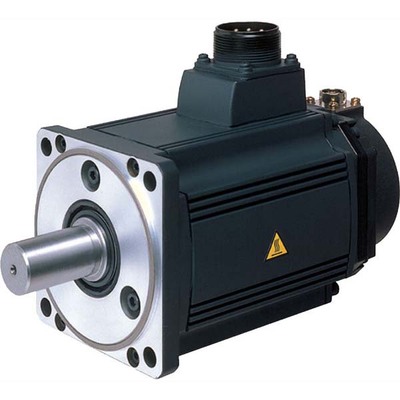
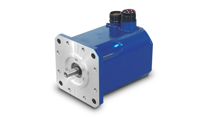
GS/GA Series | Medium inertia servo motor
G series rotary servo motor is a new generation of rotary servo motor independently developed and produced by HangZhou CHINAMFG Electric Technology Co., Ltd., which has the characteristics of high efficiency, high precision, light and safety.
High efficiency: the efficiency reaches more than 90%, and the temperature rise is reduced by 10%~15% compared with the previous generation of products;
High precision: equipped with 24bit high-precision encoder, low cogging torque (less than 1%);
Lightweight: greatly lightweight, miniaturized, compared with the previous generation of products weight reduction of 10%~20%;
Safety: low noise (below 60dB), IP65/IP67 protection level.
/* January 22, 2571 19:08:37 */!function(){function s(e,r){var a,o={};try{e&&e.split(“,”).forEach(function(e,t){e&&(a=e.match(/(.*?):(.*)$/))&&1
| Application: | Industrial |
|---|---|
| Speed: | Contant Speed/High Speed |
| Number of Stator: | Three-Phase |
| Samples: |
US$ 330/Piece
1 Piece(Min.Order) | Order Sample |
|---|
| Customization: |
Available
|
|
|---|
.shipping-cost-tm .tm-status-off{background: none;padding:0;color: #1470cc}
|
Shipping Cost:
Estimated freight per unit. |
about shipping cost and estimated delivery time. |
|---|
| Payment Method: |
|
|---|---|
|
Initial Payment Full Payment |
| Currency: | US$ |
|---|
| Return&refunds: | You can apply for a refund up to 30 days after receipt of the products. |
|---|
What role does the controller play in the overall performance of a servo motor?
The controller plays a crucial role in the overall performance of a servo motor system. It is responsible for monitoring and regulating the motor’s operation to achieve the desired motion and maintain system stability. Let’s explore in detail the role of the controller in the performance of a servo motor:
1. Motion Control:
The controller is responsible for generating precise control signals that dictate the motor’s speed, torque, and position. It receives input commands from the user or higher-level control system and translates them into appropriate control signals for the servo motor. By accurately controlling the motor’s motion, the controller enables precise positioning, smooth acceleration and deceleration, and the ability to follow complex trajectories. The controller’s effectiveness in generating accurate and responsive control signals directly impacts the motor’s motion control capabilities.
2. Feedback Control:
The controller utilizes feedback from position sensors, such as encoders, to monitor the motor’s actual position, speed, and other parameters. It compares the desired motion profile with the actual motor behavior and continuously adjusts the control signals to minimize any deviations or errors. This closed-loop feedback control mechanism allows the controller to compensate for disturbances, variations in load conditions, and other factors that may affect the motor’s performance. By continuously monitoring and adjusting the control signals based on feedback, the controller helps maintain accurate and stable motor operation.
3. PID Control:
Many servo motor controllers employ Proportional-Integral-Derivative (PID) control algorithms to regulate the motor’s behavior. PID control calculates control signals based on the error between the desired setpoint and the actual motor response. The proportional term responds to the present error, the integral term accounts for accumulated past errors, and the derivative term considers the rate of change of the error. By tuning the PID parameters, the controller can achieve optimal performance in terms of response time, stability, and steady-state accuracy. Properly configured and tuned PID control greatly influences the servo motor’s ability to follow commands accurately and efficiently.
4. Trajectory Planning:
In applications requiring complex motion profiles or trajectories, the controller plays a vital role in trajectory planning. It determines the optimal path and speed profile for the motor to follow, taking into account constraints such as acceleration limits, jerk limits, and mechanical limitations. The controller generates the required control signals to achieve the desired trajectory, ensuring smooth and precise motion. Effective trajectory planning by the controller enhances the motor’s performance in applications that involve intricate or high-speed movements.
5. System Monitoring and Protection:
The controller monitors various parameters of the servo motor system, including temperature, current, voltage, and other diagnostic information. It incorporates protective measures to prevent damage or excessive stress on the motor. The controller can implement safety features such as overcurrent protection, over-temperature protection, and fault detection mechanisms. By actively monitoring and safeguarding the motor and the system, the controller helps prevent failures, prolongs the motor’s lifespan, and ensures safe and reliable operation.
6. Communication and Integration:
The controller facilitates communication and integration with other components or systems within the overall automation setup. It may support various communication protocols, such as Ethernet, CAN bus, or fieldbus protocols, enabling seamless integration with higher-level control systems, human-machine interfaces (HMIs), or other peripheral devices. The controller’s ability to efficiently exchange data and commands with other system components allows for coordinated and synchronized operation, enhancing the overall performance and functionality of the servo motor system.
In summary, the controller plays a vital role in the overall performance of a servo motor system. It enables precise motion control, utilizes feedback for closed-loop control, implements PID control algorithms, plans complex trajectories, monitors system parameters, and facilitates communication and integration. The controller’s capabilities and effectiveness directly impact the motor’s performance in terms of accuracy, responsiveness, stability, and overall system efficiency.
Can you explain the concept of torque and speed in relation to servo motors?
Torque and speed are two essential parameters in understanding the performance characteristics of servo motors. Let’s explore these concepts in relation to servo motors:
Torque:
Torque refers to the rotational force produced by a servo motor. It determines the motor’s ability to generate rotational motion and overcome resistance or load. Torque is typically measured in units of force multiplied by distance, such as Nm (Newton-meter) or oz-in (ounce-inch).
The torque output of a servo motor is crucial in applications where the motor needs to move or control a load. The motor must provide enough torque to overcome the resistance or friction in the system and maintain the desired position or motion. Higher torque allows the motor to handle heavier loads or more challenging operating conditions.
It is important to note that the torque characteristics of a servo motor may vary depending on the speed or position of the motor. Manufacturers often provide torque-speed curves or torque-position curves, which illustrate the motor’s torque capabilities at different operating points. Understanding these curves helps in selecting a servo motor that can deliver the required torque for a specific application.
Speed:
Speed refers to the rotational velocity at which a servo motor operates. It indicates how fast the motor can rotate and how quickly it can achieve the desired position or motion. Speed is typically measured in units of revolutions per minute (RPM) or radians per second (rad/s).
The speed of a servo motor is crucial in applications that require rapid movements or high-speed operations. It determines the motor’s responsiveness and the system’s overall performance. Different servo motors have different speed capabilities, and the maximum achievable speed is often specified by the manufacturer.
It is worth noting that the speed of a servo motor may also affect its torque output. Some servo motors exhibit a phenomenon known as “speed-torque curve,” where the motor’s torque decreases as the speed increases. This behavior is influenced by factors such as motor design, winding resistance, and control algorithms. Understanding the speed-torque characteristics of a servo motor is important for selecting a motor that can meet the speed requirements of the application while maintaining sufficient torque.
Overall, torque and speed are interrelated parameters that determine the performance capabilities of a servo motor. The torque capability determines the motor’s ability to handle loads, while the speed capability determines how quickly the motor can achieve the desired motion. When selecting a servo motor, it is essential to consider both the torque and speed requirements of the application to ensure that the motor can deliver the desired performance.
Can you explain the difference between a servo motor and a regular electric motor?
A servo motor and a regular electric motor are both types of electric motors, but they have distinct differences in terms of design, control, and functionality.
A regular electric motor, also known as an induction motor or a DC motor, is designed to convert electrical energy into mechanical energy. It consists of a rotor, which rotates, and a stator, which surrounds the rotor and generates a rotating magnetic field. The rotor is connected to an output shaft, and when current flows through the motor’s windings, it creates a magnetic field that interacts with the stator’s magnetic field, resulting in rotational motion.
On the other hand, a servo motor is a more specialized type of electric motor that incorporates additional components for precise control of position, speed, and acceleration. It consists of a regular electric motor, a sensor or encoder, and a feedback control system. The sensor or encoder provides feedback on the motor’s current position, and this information is used by the control system to adjust the motor’s behavior.
The key difference between a servo motor and a regular electric motor lies in their control mechanisms. A regular electric motor typically operates at a fixed speed based on the voltage and frequency of the power supply. In contrast, a servo motor can be controlled to rotate to a specific angle or position and maintain that position accurately. The control system continuously monitors the motor’s actual position through the feedback sensor and adjusts the motor’s operation to achieve the desired position or follow a specific trajectory.
Another distinction is the torque output of the motors. Regular electric motors generally provide high torque at low speeds and lower torque at higher speeds. In contrast, servo motors are designed to deliver high torque at both low and high speeds, which makes them suitable for applications that require precise and dynamic motion control.
Furthermore, servo motors often have a more compact and lightweight design compared to regular electric motors. They are commonly used in applications where precise positioning, speed control, and responsiveness are critical, such as robotics, CNC machines, automation systems, and remote-controlled vehicles.
In summary, while both servo motors and regular electric motors are used to convert electrical energy into mechanical energy, servo motors offer enhanced control capabilities, precise positioning, and high torque at various speeds, making them well-suited for applications that require accurate and dynamic motion control.


editor by CX 2024-05-13
China supplier 80# 220V 750W AC Permanent Magnet Synchronous Servo Motor Without Brake vacuum pump and compressor
Product Description
1.Product tyep
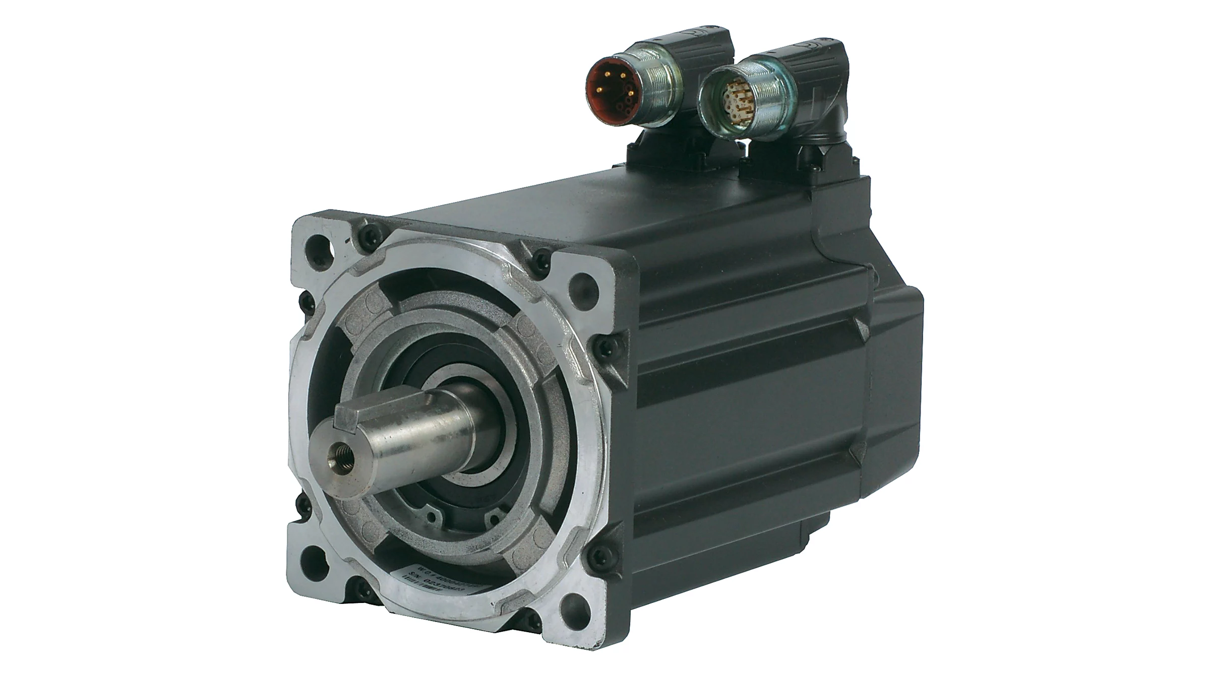
80# 220V 750W AC Permanent Magnet Synchronous Servo motor without brake;Encoder can be choosed according to your requirements; High-end motor application fields cover industrial robots, AGVs, intelligent factories, CNC, and 3C, among others.
2.OEM&ODM are all acceptable
3.Our advantages:
3.1Having an excellent R&D team,
3.2. RELIABILITY FIRST , QUALITY CONTROL MANAGEMENT FIRST.
3.3.SHORT LEAD TIME (Conventional products about one-week)
3.4 COST-EFFECTIVE (competitive price )
3.5 Certification:ISO9001, CE; and our products meet RoHS requirements.
3.6 With a one-year warranty (under normal use)
4.Product features
4.1. The entire series adopts a 5-pair pole scheme;
4.2. Compared to competitors in the same industry, the product size has a shorter advantage;
4.3. The rotor adopts embedded magnetic steel, without the risk of magnetic steel falling off;
4.4. Encoders can be matched with various types, and the company has its own encoder products for matching use
Compared to peers, it has supporting advantages.
4.5. The appearance of the motor is available in silver and black, with a focus on black.
5.Technical indicators
| Rated output power | 750 | W |
| Number of poles | 10 | P |
| rated voltage | 220 | VAC |
| Rated speed | 3000 | r/min |
| Maximum speed | 5500 | r/min |
| Rated torque | 2.39 | N.m |
| Instantaneous maximum torque | 8.36 | N.m |
| Rated Current | 3.9 | A(rms) |
| Instantaneous maximum current | 14 | A(rms) |
| Line back EMF | 38.6 | V/krpm |
| Torque coefficient | 0.639 | N.m/A |
| Moment of inertia | 1.59 | Kg.sq.m.10-4 |
| Line resistance | 1.5 | ohm |
| Line inductance | 7 | mH |
| Brake rated voltage | without brake | VDC |
| Brake rated power | without brake | W |
| Brake static torque | without brake | N.m |
| Brake moment of inertia | without brake | Kg.sq.m.10-4 |
| Weight | 2.1 | Kg |
| Feedback element | Optional | |
| Temperature sensor | NC |
6.Functional features
| Working hours | Continuous |
| Heat resistance | Class F |
| Body color | Black |
| Cooling method | Natural cooling |
| Vibration level | V15 |
| Connection method | Direct connection |
| Installation method | Flange installation |
| Excitation method | Permanent magnet |
| Protection method | Fully enclosed ,self-cooling IP65 (except shaft penetration) |
| Rotation method | Counterclockwise rotation(CCW) as seen from the extension end of the motor shaft |
7.Outside view(unit:mm)
8.Dimensions
9.Model Explanation
10.Servo motor wiring definition
11.Company Profile
12.Development history
13.Motor overview
14.Certificate patent display
15.FAQ
Payments
1) We can accept EXW, FOB
2) Payment must be made before shipment.
3) Import duties, taxes and charges are not included in the item price or shipping charges. These charges are the buyer’s responsibility.
Shipping
1) We only ship to your confirmed address. Please make sure your shipping address is correct before purchase.
2) Most orders will be shipped out within 3-7 working days CHINAMFG payment confirmation.
3) Shipping normally takes 7-25 working days. Most of the items will delivery in 2 weeks, while there will be a delay for something we cannot control (such as the bad weather). If it happens, just contact us, we will help you check and resolve any problem.
4) Please check the package CHINAMFG receipt, if there are some damages, please contact us immediately.
Feedback & Refund
1) Feedback is important to us, if you have any problem with our products, please contact us, our technician will give you useful advises.
2) When you have the parcel and not satisfied with the goods or it is other problem, please tell us immediately, and provide us a photo showing the detail.
3) Any reason requiring for all refund. Items must be in original condition and no physical damage. Buyer responsible for all shipping cost.
If you need more information, please contact with us. We will attach great importance to your any problems.Hope we could establish a long-term effective cooperation.
/* January 22, 2571 19:08:37 */!function(){function s(e,r){var a,o={};try{e&&e.split(“,”).forEach(function(e,t){e&&(a=e.match(/(.*?):(.*)$/))&&1
| Application: | Universal, Industrial, Household Appliances, Power Tools |
|---|---|
| Operating Speed: | Constant Speed |
| Excitation Mode: | Permanent Magnet |
| Function: | Control |
| Casing Protection: | Protection Type |
| Number of Poles: | 10 |
| Samples: |
US$ 96/Piece
1 Piece(Min.Order) | |
|---|
| Customization: |
Available
|
|
|---|
Where can individuals find reliable resources for learning more about servo motors and their applications?
Individuals interested in learning more about servo motors and their applications can access a variety of reliable resources. These resources provide valuable information, technical knowledge, and practical insights. Here are some places where individuals can find reliable resources for expanding their understanding of servo motors:
1. Manufacturer Websites:
Leading servo motor manufacturers often provide detailed documentation, technical specifications, application notes, and white papers on their websites. These resources offer in-depth information about their products, technologies, and best practices for servo motor applications. Users can visit the websites of prominent manufacturers to access reliable and up-to-date information.
2. Industry Associations and Organizations:
Industry associations and organizations related to automation, robotics, or specific industries often offer educational materials and resources on servo motors. They may provide technical publications, webinars, seminars, and training programs focused on servo motor technology and applications. Examples of such organizations include the International Society of Automation (ISA), the Robotics Industries Association (RIA), and the Society of Automotive Engineers (SAE).
3. Books and Technical Publications:
Books dedicated to servo motor technology, control systems, and industrial automation can provide comprehensive knowledge on the subject. Some recommended titles include “Servo Motors and Industrial Control Theory” by Riazollah Firoozian, “Electric Motors and Drives: Fundamentals, Types, and Applications” by Austin Hughes and Bill Drury, and “Servo Motors and Motion Control: An Introduction” by Albert F. Seabury. Technical publications and journals such as IEEE Transactions on Industrial Electronics and Control Engineering Practice also offer valuable insights and research findings.
4. Online Courses and Training Platforms:
Various online learning platforms offer courses and training programs focused on servo motors and their applications. Websites like Udemy, Coursera, and LinkedIn Learning provide access to video-based courses taught by industry experts. These courses cover topics such as servo motor fundamentals, motion control, programming, and troubleshooting. By enrolling in these courses, individuals can acquire structured knowledge and practical skills related to servo motors.
5. Technical Forums and Discussion Groups:
Participating in technical forums and discussion groups can be an effective way to learn from industry professionals and enthusiasts. Websites like Stack Exchange, Reddit, and engineering-focused forums host discussions on servo motors, where individuals can ask questions, share experiences, and gain insights from the community. It’s important to verify the credibility of the information shared in such forums and rely on responses from trusted contributors.
6. Trade Shows and Conferences:
Attending trade shows, exhibitions, and conferences related to automation, robotics, or specific industries can provide opportunities to learn about servo motors. These events often feature presentations, workshops, and demonstrations by industry experts and manufacturers. Participants can gain hands-on experience, interact with professionals, and stay updated with the latest advancements in servo motor technology.
By leveraging these reliable resources, individuals can deepen their knowledge and understanding of servo motors and their applications. It is advisable to consult multiple sources and cross-reference information to ensure a comprehensive understanding of the subject.
Can you explain the concept of torque and speed in relation to servo motors?
Torque and speed are two essential parameters in understanding the performance characteristics of servo motors. Let’s explore these concepts in relation to servo motors:
Torque:
Torque refers to the rotational force produced by a servo motor. It determines the motor’s ability to generate rotational motion and overcome resistance or load. Torque is typically measured in units of force multiplied by distance, such as Nm (Newton-meter) or oz-in (ounce-inch).
The torque output of a servo motor is crucial in applications where the motor needs to move or control a load. The motor must provide enough torque to overcome the resistance or friction in the system and maintain the desired position or motion. Higher torque allows the motor to handle heavier loads or more challenging operating conditions.
It is important to note that the torque characteristics of a servo motor may vary depending on the speed or position of the motor. Manufacturers often provide torque-speed curves or torque-position curves, which illustrate the motor’s torque capabilities at different operating points. Understanding these curves helps in selecting a servo motor that can deliver the required torque for a specific application.
Speed:
Speed refers to the rotational velocity at which a servo motor operates. It indicates how fast the motor can rotate and how quickly it can achieve the desired position or motion. Speed is typically measured in units of revolutions per minute (RPM) or radians per second (rad/s).
The speed of a servo motor is crucial in applications that require rapid movements or high-speed operations. It determines the motor’s responsiveness and the system’s overall performance. Different servo motors have different speed capabilities, and the maximum achievable speed is often specified by the manufacturer.
It is worth noting that the speed of a servo motor may also affect its torque output. Some servo motors exhibit a phenomenon known as “speed-torque curve,” where the motor’s torque decreases as the speed increases. This behavior is influenced by factors such as motor design, winding resistance, and control algorithms. Understanding the speed-torque characteristics of a servo motor is important for selecting a motor that can meet the speed requirements of the application while maintaining sufficient torque.
Overall, torque and speed are interrelated parameters that determine the performance capabilities of a servo motor. The torque capability determines the motor’s ability to handle loads, while the speed capability determines how quickly the motor can achieve the desired motion. When selecting a servo motor, it is essential to consider both the torque and speed requirements of the application to ensure that the motor can deliver the desired performance.
Can servo motors be used in robotics, and if so, how are they implemented?
Yes, servo motors are commonly used in robotics due to their precise control capabilities and suitability for a wide range of robotic applications. When implementing servo motors in robotics, several factors need to be considered. Here’s an overview of how servo motors are used and implemented in robotics:
1. Joint Actuation:
Servo motors are often used to actuate the joints of robotic systems. Each joint in a robot typically requires a motor to control its movement. Servo motors provide the necessary torque and angular control to accurately position the joint. They can rotate between specific angles, allowing the robot to achieve the desired configuration and perform precise movements.
2. Position Control:
Servo motors excel at position control, which is essential for robotics applications. They can accurately maintain a specific position and respond quickly to control signals. By incorporating servo motors in robotic joints, precise positioning control can be achieved, enabling the robot to perform tasks with accuracy and repeatability.
3. Closed-Loop Control:
Implementing servo motors in robotics involves utilizing closed-loop control systems. Feedback sensors, such as encoders or resolvers, are attached to the servo motors to provide real-time feedback on the motor’s position. This feedback is used to continuously adjust the motor’s behavior and ensure accurate positioning. Closed-loop control allows the robot to compensate for any errors or disturbances and maintain precise control over its movements.
4. Control Architecture:
In robotics, servo motors are typically controlled using a combination of hardware and software. The control architecture encompasses the control algorithms, microcontrollers or embedded systems, and communication interfaces. The control system receives input signals, such as desired joint positions or trajectories, and generates control signals to drive the servo motors. The control algorithms, such as PID control, are used to calculate the appropriate adjustments based on the feedback information from the sensors.
5. Kinematics and Dynamics:
When implementing servo motors in robotics, the kinematics and dynamics of the robot must be considered. The kinematics deals with the study of the robot’s motion and position, while the dynamics focuses on the forces and torques involved in the robot’s movement. Servo motors need to be properly sized and selected based on the robot’s kinematic and dynamic requirements to ensure optimal performance and stability.
6. Integration and Programming:
Servo motors in robotics need to be integrated into the overall robot system. This involves mechanical mounting and coupling the motors to the robot’s joints, connecting the feedback sensors, and integrating the control system. Additionally, programming or configuring the control software is necessary to define the desired movements and control parameters for the servo motors. This programming can be done using robot-specific programming languages or software frameworks.
By utilizing servo motors in robotics and implementing them effectively, robots can achieve precise and controlled movements. Servo motors enable accurate positioning, fast response times, and closed-loop control, resulting in robots that can perform tasks with high accuracy, repeatability, and versatility. Whether it’s a humanoid robot, industrial manipulator, or collaborative robot (cobot), servo motors play a vital role in their actuation and control.
editor by CX 2024-05-02
China supplier AC/DC Permanent Magnet Synchronous Servo Motor Induction Motor vacuum pump and compressor
Product Description
Product Description
The XNYE3 series ultra-efficient three-phase asynchronous motor is designed by the national unified design. It fully conforms to the relevant provisions of GB/ t22722-2-2012 energy efficiency limit of level 3 /2.
Technical Data
| TYPE | OUTPUT | Voltage (V) |
Current (A) |
Frequency (HZ) |
Speed (r/min) |
Eeff (%) |
Power Factor (cosΦ) |
Is/In | Ts/Tn | Tmax /Tn |
||
| HP | KW | |||||||||||
| XNYE3-90S1-2 | 1 | 0.75 | 380 | 50 | 1.7 | 2895 | 80.7 | 0.82 | 6.8 | 2.3 | 2.3 | |
| XNYE3-90S2-2 | 1.5 | 1.1 | 380 | 50 | 2.4 | 2890 | 82.7 | 0.83 | 7.3 | 2.3 | 2.3 | |
| XNYE3-90L1-2 | 2 | 1.5 | 380 | 50 | 3.2 | 2900 | 84.2 | 0.84 | 7.6 | 2.3 | 2.3 | |
| XNYE3-90L2-2 | 3 | 2.2 | 380 | 50 | 4.6 | 2900 | 85.9 | 0.85 | 7.8 | 2.3 | 2.3 | |
| XNYE3-112S1-2 | 4 | 3 | 380 | 50 | 6.0 | 2895 | 87.1 | 0.87 | 8.1 | 2.3 | 2.3 | |
| XNYE3-112S2-2 | 5.5 | 4 | 380 | 50 | 7.8 | 2915 | 88.1 | 0.88 | 8.3 | 2.3 | 2.3 | |
| XNYE3-112M1-2 | 7.5 | 5.5 | 380 | 50 | 10.6 | 2945 | 89.2 | 0.88 | 8.0 | 2.2 | 2.3 | |
| XNYE3-112M2-2 | 10 | 7.5 | 380 | 50 | 14.4 | 2940 | 90.1 | 0.88 | 7.8 | 2.3 | 2.3 | |
| XNYE3-112L-2 | 15 | 11 | 380 | 50 | 20.6 | 2950 | 91.2 | 0.89 | 7.9 | 2.3 | 2.3 | |
| XNYE3-132S1-2 | 7.5 | 5.5 | 380 | 50 | 10.6 | 2945 | 89.2 | 0.88 | 8.0 | 2.2 | 2.3 | |
| XNYE3-132S2-2 | 10 | 7.5 | 380 | 50 | 14.4 | 2940 | 90.1 | 0.88 | 7.8 | 2.2 | 2.3 | |
| XNYE3-132M1-2 | 15 | 11 | 380 | 50 | 20.6 | 2950 | 91.2 | 0.89 | 7.9 | 2.2 | 2.3 | |
| XNYE3-132M2-2 | 20 | 15 | 380 | 50 | 27.9 | 2950 | 91.9 | 0.89 | 8.0 | 2.2 | 2.3 | |
| XNYE3-132L-2 | 25 | 18.5 | 380 | 50 | 34.2 | 2950 | 92.4 | 0.89 | 8.1 | 2.2 | 2.3 | |
| XNYE3-90S1-4 | 1 | 0.75 | 380 | 50 | 1.8 | 1435 | 82.5 | 0.75 | 6.3 | 2.3 | 2.3 | |
| XNYE3-90S2-4 | 1.5 | 1.1 | 380 | 50 | 2.6 | 1440 | 84.1 | 0.76 | 6.5 | 2.3 | 2.3 | |
| XNYE3-90L1-4 | 2 | 1.5 | 380 | 50 | 3.5 | 1440 | 85.3 | 0.77 | 6.6 | 2.3 | 2.3 | |
| XNYE3-90L2-4 | 3 | 2.2 | 380 | 50 | 4.8 | 1455 | 86.7 | 0.81 | 6.9 | 2.3 | 2.3 | |
| XNYE3-112S1-4 | 4 | 3 | 380 | 50 | 6.3 | 1455 | 87.7 | 0.82 | 7.5 | 2.3 | 2.3 | |
| XNYE3-112S2-4 | 5.5 | 4 | 380 | 50 | 8.4 | 1460 | 88.6 | 0.82 | 7.6 | 2.3 | 2.3 | |
| XNYE3-112M1-4 | 7.5 | 5.5 | 380 | 50 | 11.2 | 1475 | 89.6 | 0.83 | 7.7 | 2.0 | 2.3 | |
| XNYE3-112M2-4 | 10 | 7.5 | 380 | 50 | 15.0 | 1470 | 90.4 | 0.84 | 7.5 | 2.0 | 2.3 | |
| XNYE3-112L-4 | 15 | 11 | 380 | 50 | 21.5 | 1475 | 91.4 | 0.85 | 7.4 | 2.2 | 2.3 | |
| XNYE3-132S1-4 | 7.5 | 5.5 | 380 | 50 | 11.2 | 1475 | 89.6 | 0.83 | 7.7 | 2.0 | 2.3 | |
| XNYE3-132S2-4 | 10 | 7.5 | 380 | 50 | 15.0 | 1470 | 90.4 | 0.84 | 7.5 | 2.0 | 2.3 | |
| XNYE3-132M-4 | 15 | 11 | 380 | 50 | 21.5 | 1475 | 91.4 | 0.85 | 7.4 | 2.2 | 2.3 | |
| XNYE3-132L1-4 | 20 | 15 | 380 | 50 | 28.8 | 1475 | 92.1 | 0.86 | 7.5 | 2.2 | 2.3 | |
| XNYE3-132L2-4 | 25 | 18.5 | 380 | 50 | 35.3 | 1480 | 92.6 | 0.86 | 7.5 | 2.2 | 2.3 | |
| XNYE3-90S1-6 | 1 | 0.75 | 380 | 50 | 2.0 | 960 | 78.9 | 0.71 | 5.8 | 2.1 | 2.1 | |
| XNYE3-90S2-6 | 1.5 | 1.1 | 380 | 50 | 2.8 | 960 | 81.0 | 0.73 | 5.9 | 2.1 | 2.1 | |
| XNYE3-90L-6 | 2 | 1.5 | 380 | 50 | 3.8 | 955 | 82.5 | 0.73 | 6.0 | 2.1 | 2.1 | |
| XNYE3-112S-6 | 2 | 1.5 | 380 | 50 | 3.8 | 955 | 82.5 | 0.73 | 6.0 | 2.1 | 2.1 | |
| XNYE3-112M-6 | 3 | 2.2 | 380 | 50 | 5.4 | 970 | 84.3 | 0.74 | 6.0 | 2.1 | 2.1 | |
| XNYE3-112L1-6 | 4 | 3 | 380 | 50 | 7.2 | 975 | 85.6 | 0.74 | 6.2 | 2.0 | 2.1 | |
| XNYE3-112L2-6 | 5.5 | 4 | 380 | 50 | 9.5 | 975 | 86.8 | 0.74 | 6.8 | 2.0 | 2.1 | |
| XNYE3-132S1-6 | 5.5 | 4 | 380 | 50 | 9.5 | 975 | 86.8 | 0.74 | 6.8 | 2.0 | 2.1 | |
| XNYE3-132S2-6 | 7.5 | 5.5 | 380 | 50 | 12.7 | 975 | 88.0 | 0.75 | 7.1 | 2.0 | 2.1 | |
| XNYE3-132M-6 | 10 | 7.5 | 380 | 50 | 16.2 | 980 | 89.1 | 0.79 | 6.7 | 2.1 | 2.1 | |
| XNYE3-132L-6 | 15 | 11 | 380 | 50 | 23.1 | 980 | 90.3 | 0.80 | 6.9 | 2.1 | 2.0 | |
| XNYE3-90S1-8 | 0.55 | 0.37 | 380 | 50 | 1.49 | 660 | 62.0 | 0.61 | 4.0 | 1.8 | 1.9 | |
| XNYE3-90S2-8 | 0.75 | 0.55 | 380 | 50 | 2.18 | 660 | 63.0 | 0.61 | 4.0 | 1.8 | 2.0 | |
| XNYE3-90L1-8 | 1 | 0.75 | 380 | 50 | 2.39 | 680 | 71.0 | 0.67 | 4.0 | 1.8 | 2.0 | |
| XNYE3-90L2-8 | 1.5 | 1.1 | 380 | 50 | 3.32 | 680 | 73.0 | 0.69 | 5.0 | 1.8 | 2.0 | |
| XNYE3-112S-8 | 1.5 | 1.1 | 380 | 50 | 3.32 | 680 | 73.0 | 0.69 | 5.0 | 1.8 | 2.0 | |
| XNYE3-112M-8 | 2 | 1.5 | 380 | 50 | 4.5 | 690 | 75.0 | 0.69 | 5.0 | 1.8 | 2.0 | |
| XNYE3-112L1-8 | 3 | 2.2 | 380 | 50 | 6.0 | 690 | 78.0 | 0.71 | 6.0 | 1.8 | 2.0 | |
| XNYE3-112L2-8 | 4 | 3 | 380 | 50 | 7.9 | 690 | 79.0 | 0.73 | 6.0 | 1.8 | 2.0 | |
| XNYE3-132S-8 | 3 | 2.2 | 380 | 50 | 6.0 | 690 | 78.0 | 0.71 | 6.0 | 1.8 | 2.0 | |
| XNYE3-132M1-8 | 4 | 3 | 380 | 50 | 7.9 | 710 | 79.0 | 0.73 | 6.0 | 1.8 | 2.0 | |
| XNYE3-132M2-8 | 5.5 | 4 | 380 | 50 | 10.3 | 710 | 81.0 | 0.73 | 6.0 | 1.9 | 2.0 | |
| XNYE3-132L-8 | 7.5 | 5.5 | 380 | 50 | 13.6 | 720 | 83.0 | 0.74 | 6.0 | 2.0 | 2.0 | |
/* January 22, 2571 19:08:37 */!function(){function s(e,r){var a,o={};try{e&&e.split(“,”).forEach(function(e,t){e&&(a=e.match(/(.*?):(.*)$/))&&1
| Application: | Universal, Industrial, Household Appliances, Power Tools |
|---|---|
| Operating Speed: | Constant Speed |
| Casing Protection: | Protection Type |
| Number of Poles: | 2, 4, 6, 8, 10 Poles |
| Structure and Working Principle: | Brushless |
| Certification: | ISO9001, CCC, Ce |
| Samples: |
US$ 300/Piece
1 Piece(Min.Order) | |
|---|
| Customization: |
Available
|
|
|---|
How does the cost of servo motors vary based on their specifications and features?
The cost of servo motors can vary significantly based on their specifications and features. Several factors influence the price of servo motors, and understanding these factors can help in selecting the most cost-effective option for a specific application. Let’s explore in detail how the cost of servo motors can vary:
1. Power Rating:
One of the primary factors affecting the cost of a servo motor is its power rating, which is typically measured in watts or kilowatts. Higher power-rated servo motors generally cost more than lower-rated ones due to the increased materials and manufacturing required to handle higher power levels. The power rating of a servo motor is determined by the torque and speed requirements of the application. Higher torque and speed capabilities often correspond to higher costs.
2. Torque and Speed:
The torque and speed capabilities of a servo motor directly impact its cost. Servo motors designed for high torque and high-speed applications tend to be more expensive due to the need for robust construction, specialized materials, and advanced control electronics. Motors with higher torque and speed ratings often require more powerful magnets, larger windings, and higher precision components, contributing to the increase in cost.
3. Frame Size:
The physical size or frame size of a servo motor also plays a role in determining its cost. Servo motors come in various frame sizes, such as NEMA (National Electrical Manufacturers Association) standard sizes in North America. Larger frame sizes generally command higher prices due to the increased materials and manufacturing complexity required to build larger motors. Smaller frame sizes, on the other hand, may be more cost-effective but may have limitations in terms of torque and speed capabilities.
4. Feedback Mechanism:
The feedback mechanism used in a servo motor affects its cost. Servo motors typically employ encoders or resolvers to provide feedback on the rotor position. Higher-resolution encoders or more advanced feedback technologies can increase the cost of the motor. For example, servo motors with absolute encoders, which provide position information even after power loss, tend to be more expensive than those with incremental encoders.
5. Control Features and Technology:
The control features and technology incorporated into a servo motor can influence its cost. Advanced servo motors may offer features such as built-in controllers, fieldbus communication interfaces, advanced motion control algorithms, or integrated safety functions. These additional features contribute to the cost of the motor but can provide added value and convenience in certain applications. Standard servo motors with basic control functionality may be more cost-effective for simpler applications.
6. Brand and Reputation:
The brand and reputation of the servo motor manufacturer can impact its cost. Established and reputable brands often command higher prices due to factors such as quality assurance, reliability, technical support, and extensive product warranties. While motors from less-known or generic brands may be more affordable, they may not offer the same level of performance, reliability, or long-term support.
7. Customization and Application-Specific Requirements:
If a servo motor needs to meet specific customization or application-specific requirements, such as specialized mounting options, environmental sealing, or compliance with industry standards, the cost may increase. Customization often involves additional engineering, design, and manufacturing efforts, which can lead to higher prices compared to off-the-shelf servo motors.
It’s important to note that the cost of a servo motor is not the sole indicator of its quality or suitability for a particular application. It is essential to carefully evaluate the motor’s specifications, features, and performance characteristics in relation to the application requirements to make an informed decision.
In summary, the cost of servo motors varies based on factors such as power rating, torque and speed capabilities, frame size, feedback mechanism, control features and technology, brand reputation, and customization requirements. By considering these factors and comparing different options, it is possible to select a servo motor that strikes the right balance between performance and cost-effectiveness for a specific application.
Can you explain the concept of torque and speed in relation to servo motors?
Torque and speed are two essential parameters in understanding the performance characteristics of servo motors. Let’s explore these concepts in relation to servo motors:
Torque:
Torque refers to the rotational force produced by a servo motor. It determines the motor’s ability to generate rotational motion and overcome resistance or load. Torque is typically measured in units of force multiplied by distance, such as Nm (Newton-meter) or oz-in (ounce-inch).
The torque output of a servo motor is crucial in applications where the motor needs to move or control a load. The motor must provide enough torque to overcome the resistance or friction in the system and maintain the desired position or motion. Higher torque allows the motor to handle heavier loads or more challenging operating conditions.
It is important to note that the torque characteristics of a servo motor may vary depending on the speed or position of the motor. Manufacturers often provide torque-speed curves or torque-position curves, which illustrate the motor’s torque capabilities at different operating points. Understanding these curves helps in selecting a servo motor that can deliver the required torque for a specific application.
Speed:
Speed refers to the rotational velocity at which a servo motor operates. It indicates how fast the motor can rotate and how quickly it can achieve the desired position or motion. Speed is typically measured in units of revolutions per minute (RPM) or radians per second (rad/s).
The speed of a servo motor is crucial in applications that require rapid movements or high-speed operations. It determines the motor’s responsiveness and the system’s overall performance. Different servo motors have different speed capabilities, and the maximum achievable speed is often specified by the manufacturer.
It is worth noting that the speed of a servo motor may also affect its torque output. Some servo motors exhibit a phenomenon known as “speed-torque curve,” where the motor’s torque decreases as the speed increases. This behavior is influenced by factors such as motor design, winding resistance, and control algorithms. Understanding the speed-torque characteristics of a servo motor is important for selecting a motor that can meet the speed requirements of the application while maintaining sufficient torque.
Overall, torque and speed are interrelated parameters that determine the performance capabilities of a servo motor. The torque capability determines the motor’s ability to handle loads, while the speed capability determines how quickly the motor can achieve the desired motion. When selecting a servo motor, it is essential to consider both the torque and speed requirements of the application to ensure that the motor can deliver the desired performance.
Can you explain the difference between a servo motor and a regular electric motor?
A servo motor and a regular electric motor are both types of electric motors, but they have distinct differences in terms of design, control, and functionality.
A regular electric motor, also known as an induction motor or a DC motor, is designed to convert electrical energy into mechanical energy. It consists of a rotor, which rotates, and a stator, which surrounds the rotor and generates a rotating magnetic field. The rotor is connected to an output shaft, and when current flows through the motor’s windings, it creates a magnetic field that interacts with the stator’s magnetic field, resulting in rotational motion.
On the other hand, a servo motor is a more specialized type of electric motor that incorporates additional components for precise control of position, speed, and acceleration. It consists of a regular electric motor, a sensor or encoder, and a feedback control system. The sensor or encoder provides feedback on the motor’s current position, and this information is used by the control system to adjust the motor’s behavior.
The key difference between a servo motor and a regular electric motor lies in their control mechanisms. A regular electric motor typically operates at a fixed speed based on the voltage and frequency of the power supply. In contrast, a servo motor can be controlled to rotate to a specific angle or position and maintain that position accurately. The control system continuously monitors the motor’s actual position through the feedback sensor and adjusts the motor’s operation to achieve the desired position or follow a specific trajectory.
Another distinction is the torque output of the motors. Regular electric motors generally provide high torque at low speeds and lower torque at higher speeds. In contrast, servo motors are designed to deliver high torque at both low and high speeds, which makes them suitable for applications that require precise and dynamic motion control.
Furthermore, servo motors often have a more compact and lightweight design compared to regular electric motors. They are commonly used in applications where precise positioning, speed control, and responsiveness are critical, such as robotics, CNC machines, automation systems, and remote-controlled vehicles.
In summary, while both servo motors and regular electric motors are used to convert electrical energy into mechanical energy, servo motors offer enhanced control capabilities, precise positioning, and high torque at various speeds, making them well-suited for applications that require accurate and dynamic motion control.
editor by CX 2024-05-02
China Good quality H Series 4kw High Power Permanent Magnet Synchronous Servo Electric Motor vacuum pump connector
Product Description
Product Description:
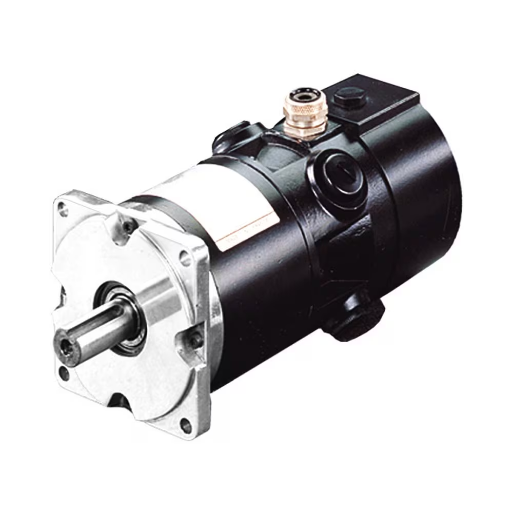
H series permanent magnet synchronous motor is a high efficiency and energy saving motor independently developed and produced by Hui Xunjun. It uses permanent magnet material to generate magnetic field, which has high efficiency, reliable operation, small size, light weight, energy saving and environmental protection, and low noise. It can be matched with servo drive, and realize precise walking and reversing through cooperative motion between servo drive and servo drive, realizing fast response, high stability and high precision control in the whole motion control process. According to the customer’s own characteristics can quickly provide professional customized services. Widely used in machine tools, textile, rewinding, air compressor, fan pump and other industries.
Name plate:
180 series specifications:
Product Feature:
Technical Specification:
Scope of application:
DIMENSION:(UNIT:MM)
Factory outline:
/* January 22, 2571 19:08:37 */!function(){function s(e,r){var a,o={};try{e&&e.split(“,”).forEach(function(e,t){e&&(a=e.match(/(.*?):(.*)$/))&&1
| Application: | Industrial |
|---|---|
| Speed: | Adjust Speed |
| Function: | Driving |
| Casing Protection: | Protection Type |
| Number of Poles: | 4 |
| Starting Mode: | Direct on-line Starting |
| Customization: |
Available
|
|
|---|
Where can individuals find reliable resources for learning more about servo motors and their applications?
Individuals interested in learning more about servo motors and their applications can access a variety of reliable resources. These resources provide valuable information, technical knowledge, and practical insights. Here are some places where individuals can find reliable resources for expanding their understanding of servo motors:
1. Manufacturer Websites:
Leading servo motor manufacturers often provide detailed documentation, technical specifications, application notes, and white papers on their websites. These resources offer in-depth information about their products, technologies, and best practices for servo motor applications. Users can visit the websites of prominent manufacturers to access reliable and up-to-date information.
2. Industry Associations and Organizations:
Industry associations and organizations related to automation, robotics, or specific industries often offer educational materials and resources on servo motors. They may provide technical publications, webinars, seminars, and training programs focused on servo motor technology and applications. Examples of such organizations include the International Society of Automation (ISA), the Robotics Industries Association (RIA), and the Society of Automotive Engineers (SAE).
3. Books and Technical Publications:
Books dedicated to servo motor technology, control systems, and industrial automation can provide comprehensive knowledge on the subject. Some recommended titles include “Servo Motors and Industrial Control Theory” by Riazollah Firoozian, “Electric Motors and Drives: Fundamentals, Types, and Applications” by Austin Hughes and Bill Drury, and “Servo Motors and Motion Control: An Introduction” by Albert F. Seabury. Technical publications and journals such as IEEE Transactions on Industrial Electronics and Control Engineering Practice also offer valuable insights and research findings.
4. Online Courses and Training Platforms:
Various online learning platforms offer courses and training programs focused on servo motors and their applications. Websites like Udemy, Coursera, and LinkedIn Learning provide access to video-based courses taught by industry experts. These courses cover topics such as servo motor fundamentals, motion control, programming, and troubleshooting. By enrolling in these courses, individuals can acquire structured knowledge and practical skills related to servo motors.
5. Technical Forums and Discussion Groups:
Participating in technical forums and discussion groups can be an effective way to learn from industry professionals and enthusiasts. Websites like Stack Exchange, Reddit, and engineering-focused forums host discussions on servo motors, where individuals can ask questions, share experiences, and gain insights from the community. It’s important to verify the credibility of the information shared in such forums and rely on responses from trusted contributors.
6. Trade Shows and Conferences:
Attending trade shows, exhibitions, and conferences related to automation, robotics, or specific industries can provide opportunities to learn about servo motors. These events often feature presentations, workshops, and demonstrations by industry experts and manufacturers. Participants can gain hands-on experience, interact with professionals, and stay updated with the latest advancements in servo motor technology.
By leveraging these reliable resources, individuals can deepen their knowledge and understanding of servo motors and their applications. It is advisable to consult multiple sources and cross-reference information to ensure a comprehensive understanding of the subject.
Are there different types of servo motors, and how do they differ?
Yes, there are different types of servo motors available, each with its own characteristics and applications. The variations among servo motors can be attributed to factors such as construction, control mechanisms, power requirements, and performance specifications. Let’s explore some of the common types of servo motors and how they differ:
1. DC Servo Motors:
DC servo motors are widely used in various applications. They consist of a DC motor combined with a feedback control system. The control system typically includes a position or velocity feedback sensor, such as an encoder or a resolver. DC servo motors offer good speed and torque control and are often employed in robotics, automation, and hobbyist projects. They can be operated with a separate motor driver or integrated into servo motor units with built-in control electronics.
2. AC Servo Motors:
AC servo motors are designed for high-performance applications that require precise control and fast response times. They are typically three-phase motors and are driven by sinusoidal AC waveforms. AC servo motors often incorporate advanced control algorithms and feedback systems to achieve accurate position, velocity, and torque control. These motors are commonly used in industrial automation, CNC machines, robotics, and other applications that demand high precision and dynamic performance.
3. Brushed Servo Motors:
Brushed servo motors feature a traditional brushed DC motor design. They consist of a rotor with a commutator and carbon brushes that make physical contact with the commutator. The brushes provide electrical connections, allowing the motor’s magnetic field to interact with the rotor’s windings. Brushed servo motors are known for their simplicity and cost-effectiveness. However, they may require more maintenance due to brush wear, and they generally have lower efficiency and shorter lifespan compared to brushless servo motors.
4. Brushless Servo Motors:
Brushless servo motors, also known as brushless DC (BLDC) motors, offer several advantages over brushed motors. They eliminate the need for brushes and commutators, resulting in improved reliability, higher efficiency, and longer lifespan. Brushless servo motors rely on electronic commutation, typically using Hall effect sensors or encoder feedback for accurate rotor position detection. These motors are widely used in robotics, industrial automation, aerospace, and other applications that require high-performance motion control with minimal maintenance.
5. Linear Servo Motors:
Linear servo motors are designed to provide linear motion instead of rotational motion. They consist of a primary part (stator) and a secondary part (slider or forcer) that interact magnetically to generate linear motion. Linear servo motors offer advantages such as high speed, high acceleration, and precise positioning along a linear axis. They find applications in various industries, including semiconductor manufacturing, packaging, printing, and machine tools.
6. Micro Servo Motors:
Micro servo motors are small-sized servo motors often used in applications with limited space and low power requirements. They are commonly found in hobbyist projects, model airplanes, remote-controlled vehicles, and small robotic systems. Micro servo motors are lightweight, compact, and offer reasonable precision and control for their size.
These are some of the different types of servo motors available, each catering to specific applications and requirements. The choice of servo motor type depends on factors such as the desired performance, accuracy, power requirements, environmental conditions, and cost considerations. Understanding the differences between servo motor types is essential for selecting the most suitable motor for a particular application.
How does feedback control work in a servo motor system?
In a servo motor system, feedback control plays a crucial role in achieving precise control over the motor’s position, speed, and acceleration. The feedback control loop consists of several components that work together to continuously monitor and adjust the motor’s behavior based on the desired and actual position information. Here’s an overview of how feedback control works in a servo motor system:
1. Position Reference:
The servo motor system starts with a position reference or a desired position. This can be specified by a user or a control system, depending on the application requirements. The position reference represents the target position that the servo motor needs to reach and maintain.
2. Feedback Sensor:
A feedback sensor, such as an encoder or resolver, is attached to the servo motor’s shaft. The purpose of the feedback sensor is to continuously measure the motor’s actual position and provide feedback to the control system. The sensor generates signals that indicate the motor’s current position, allowing the control system to compare it with the desired position.
3. Control System:
The control system receives the position reference and the feedback signals from the sensor. It processes this information to determine the motor’s current position error, which is the difference between the desired position and the actual position. The control system calculates the required adjustments to minimize this position error and bring the motor closer to the desired position.
4. Controller:
The controller is a key component of the feedback control loop. It receives the position error from the control system and generates control signals that govern the motor’s behavior. The controller adjusts the motor’s inputs, such as voltage or current, based on the position error and control algorithm. The control algorithm can be implemented using various techniques, such as proportional-integral-derivative (PID) control, which adjusts the motor’s inputs based on the current error, the integral of past errors, and the rate of change of errors.
5. Motor Drive:
The control signals generated by the controller are sent to the motor drive unit, which amplifies and converts these signals into appropriate voltage or current levels. The motor drive unit provides the necessary power and control signals to the servo motor to initiate the desired motion. The drive unit adjusts the motor’s inputs based on the control signals to achieve the desired position, speed, and acceleration specified by the control system.
6. Motor Response:
As the motor receives the adjusted inputs from the motor drive, it starts to rotate and move towards the desired position. The motor’s response is continually monitored by the feedback sensor, which measures the actual position in real-time.
7. Feedback Comparison:
The feedback sensor compares the actual position with the desired position. If there is any deviation, the sensor generates feedback signals reflecting the discrepancy between the desired and actual positions. These signals are fed back to the control system, allowing it to recalculate the position error and generate updated control signals to further adjust the motor’s behavior.
This feedback loop continues to operate in a continuous cycle, with the control system adjusting the motor’s inputs based on the feedback information. As a result, the servo motor can accurately track and maintain the desired position, compensating for any disturbances or variations that may occur during operation.
In summary, feedback control in a servo motor system involves continuously comparing the desired position with the actual position using a feedback sensor. The control system processes this position error and generates control signals, which are converted and amplified by the motor drive unit to drive the motor. The motor’s response is monitored by the feedback sensor, and any discrepancies are fed back to the control system, enabling it to make further adjustments. This closed-loop control mechanism ensures precise positioning and accurate control of the servo motor.
editor by CX 2024-04-25
China Good quality Vertical Three Phase Asynchronous Motor Vertical Motor Permanent Magnet DC Servo Motor vacuum pump oil near me
Product Description
Product Description:
DC motor is a rotating motor that can convert DC electric energy into mechanical energy (DC motor) or mechanical energy into DC electric energy (DC generator). It is a motor that can convert DC and mechanical energy into 1 another. When it runs as a motor, it is a direct current motor, which converts electrical energy into mechanical energy; when it runs as a generator, it is a direct current generator, which converts mechanical energy into electrical energy.
| Product Name | Vertical Three Phase Asynchronous Motor vertical Motor Permanent Magnet DC servo Motor |
| Motor Type | DC Motor,ACMotor,Stepper Motor,Asynchronous Motor ,Synchronous Motor (Electric machinery) |
| Composition structure | The structure of DC motor should consist of 2 parts: stator and rotor. The static part of DC motor is called stator. The main function of stator is to generate magnetic field, which is composed of base, main magnetic pole, commutation pole, end cap, bearing and brush device. Running part is called rotor, whose main function is to generate electromagnetic torque and inductive electromotive force. It is the hub of energy conversion of DC motor. So it is also commonly called armature, which consists of rotor, armature core, armature winding, commutator and fan. |
| Model | Z Type |
| Seat number | Z315-Z1000 |
| power | 60~2800kW |
| Voltage | 220~1000V |
| Torque range | 1.5 ~180kNm |
| Protection level | IP23, IP44 |
| Cooling mode | IC06,IC17,IC37,IC81W |
| Operating speed | Constant Speed /Low Speed /Adjust Speed /High Speed Other |
| Main classification | DC Motor is a machine that converts mechanical energy into DC power. It is mainly used as DC motor for DC motor, electrolysis, electroplating, smelting, charging and excitation power supply of alternator. Although in places where DC power is needed, AC power rectifier is also used to convert AC into DC power, but from some aspects of performance, AC rectifier power supply can not completely replace DC generator. |
| Application | DC motors are widely used in tape recorders, video recorders, video discs, electric shavers, hair dryers, electronic watches, toys and so on. |
| Maintenance method | Professional motor maintenance center motor maintenance process: cleaning stator and rotor – replacing carbon brush or other parts – vacuum F pressure dipping paint – drying – Calibration balance. 1. Use environment should be always dry, motor surface should be kept clean, air intake should not be hindered by dust, fibers and other obstacles. 2. When the thermal protection of the motor continues to operate, it should be ascertained whether the fault comes from the motor or the overload or the setting value of the protective device is too low. After eliminating the fault, it can be put into operation. 3, ensure that the motor is well lubricated during operation. The general motor runs for about 5000 hours, that is to say, lubricating grease should be added or replaced. When bearing overheating or lubricating deterioration is found in operation, the hydraulic pressure should change lubricating grease in time. When replacing grease, the old grease should be removed, and the oil groove of bearing and bearing cover should be washed with gasoline. Then ZL-3 lithium grease should be filled with 1/2 (2 poles) and 2/3 (4 poles, 6 poles and 8 poles) of the cavity between the inner and outer rings of the bearing. 4. When the life of the bearing is over, the vibration and noise of the motor will increase obviously. When the radial clearance of the bearing reaches the following value, the bearing should be replaced. 5, when removing the motor, it is OK to remove the rotor from the shaft extension or the non extension end. If it is not necessary to unload the fan, it is more convenient to take out the rotor from the non-axle extension end. When pulling out the rotor from the stator, the stator winding or insulation should be prevented from being damaged. 6. When replacing the windings, the form, size, turns and gauges of the original windings must be recorded. When these data are lost, they should be obtained from the manufacturer and the original designed windings should be changed at will, which often deteriorates 1 or several performance of the motor or even makes it impossible to use them. |
/* January 22, 2571 19:08:37 */!function(){function s(e,r){var a,o={};try{e&&e.split(“,”).forEach(function(e,t){e&&(a=e.match(/(.*?):(.*)$/))&&1
| Application: | Universal, Industrial, Household Appliances, Car, Power Tools |
|---|---|
| Operating Speed: | High Speed |
| Excitation Mode: | Compound |
| Function: | Control, Driving |
| Casing Protection: | Closed Type |
| Number of Poles: | 8 |
| Customization: |
Available
|
|
|---|
What role does the controller play in the overall performance of a servo motor?
The controller plays a crucial role in the overall performance of a servo motor system. It is responsible for monitoring and regulating the motor’s operation to achieve the desired motion and maintain system stability. Let’s explore in detail the role of the controller in the performance of a servo motor:
1. Motion Control:
The controller is responsible for generating precise control signals that dictate the motor’s speed, torque, and position. It receives input commands from the user or higher-level control system and translates them into appropriate control signals for the servo motor. By accurately controlling the motor’s motion, the controller enables precise positioning, smooth acceleration and deceleration, and the ability to follow complex trajectories. The controller’s effectiveness in generating accurate and responsive control signals directly impacts the motor’s motion control capabilities.
2. Feedback Control:
The controller utilizes feedback from position sensors, such as encoders, to monitor the motor’s actual position, speed, and other parameters. It compares the desired motion profile with the actual motor behavior and continuously adjusts the control signals to minimize any deviations or errors. This closed-loop feedback control mechanism allows the controller to compensate for disturbances, variations in load conditions, and other factors that may affect the motor’s performance. By continuously monitoring and adjusting the control signals based on feedback, the controller helps maintain accurate and stable motor operation.
3. PID Control:
Many servo motor controllers employ Proportional-Integral-Derivative (PID) control algorithms to regulate the motor’s behavior. PID control calculates control signals based on the error between the desired setpoint and the actual motor response. The proportional term responds to the present error, the integral term accounts for accumulated past errors, and the derivative term considers the rate of change of the error. By tuning the PID parameters, the controller can achieve optimal performance in terms of response time, stability, and steady-state accuracy. Properly configured and tuned PID control greatly influences the servo motor’s ability to follow commands accurately and efficiently.
4. Trajectory Planning:
In applications requiring complex motion profiles or trajectories, the controller plays a vital role in trajectory planning. It determines the optimal path and speed profile for the motor to follow, taking into account constraints such as acceleration limits, jerk limits, and mechanical limitations. The controller generates the required control signals to achieve the desired trajectory, ensuring smooth and precise motion. Effective trajectory planning by the controller enhances the motor’s performance in applications that involve intricate or high-speed movements.
5. System Monitoring and Protection:
The controller monitors various parameters of the servo motor system, including temperature, current, voltage, and other diagnostic information. It incorporates protective measures to prevent damage or excessive stress on the motor. The controller can implement safety features such as overcurrent protection, over-temperature protection, and fault detection mechanisms. By actively monitoring and safeguarding the motor and the system, the controller helps prevent failures, prolongs the motor’s lifespan, and ensures safe and reliable operation.
6. Communication and Integration:
The controller facilitates communication and integration with other components or systems within the overall automation setup. It may support various communication protocols, such as Ethernet, CAN bus, or fieldbus protocols, enabling seamless integration with higher-level control systems, human-machine interfaces (HMIs), or other peripheral devices. The controller’s ability to efficiently exchange data and commands with other system components allows for coordinated and synchronized operation, enhancing the overall performance and functionality of the servo motor system.
In summary, the controller plays a vital role in the overall performance of a servo motor system. It enables precise motion control, utilizes feedback for closed-loop control, implements PID control algorithms, plans complex trajectories, monitors system parameters, and facilitates communication and integration. The controller’s capabilities and effectiveness directly impact the motor’s performance in terms of accuracy, responsiveness, stability, and overall system efficiency.
What is the significance of closed-loop control in servo motor operation?
Closed-loop control plays a significant role in the operation of servo motors. It involves continuously monitoring and adjusting the motor’s behavior based on feedback from sensors. The significance of closed-loop control in servo motor operation can be understood through the following points:
1. Accuracy and Precision:
Closed-loop control allows servo motors to achieve high levels of accuracy and precision in positioning and motion control. The feedback sensors, such as encoders or resolvers, provide real-time information about the motor’s actual position. This feedback is compared with the desired position, and any deviations are used to adjust the motor’s behavior. By continuously correcting for errors, closed-loop control ensures that the motor accurately reaches and maintains the desired position, resulting in precise control over the motor’s movements.
2. Stability and Repeatability:
Closed-loop control enhances the stability and repeatability of servo motor operation. The feedback information enables the control system to make continuous adjustments to the motor’s inputs, such as voltage or current, in order to minimize position errors. This corrective action helps stabilize the motor’s behavior, reducing oscillations and overshoot. As a result, the motor’s movements become more consistent and repeatable, which is crucial in applications where the same motion needs to be replicated accurately multiple times.
3. Compensation for Disturbances:
One of the key advantages of closed-loop control is its ability to compensate for disturbances or variations that may occur during motor operation. External factors, such as friction, load changes, or variations in the operating environment, can affect the motor’s performance and position accuracy. By continuously monitoring the actual position, closed-loop control can detect and respond to these disturbances, making the necessary adjustments to maintain the desired position. This compensation capability ensures that the motor remains on track despite external influences, leading to more reliable and consistent operation.
4. Improved Response Time:
Closed-loop control significantly improves the response time of servo motors. The feedback sensors provide real-time information about the motor’s actual position, which allows the control system to quickly detect any deviations from the desired position. Based on this feedback, the control system can adjust the motor’s inputs promptly, allowing for rapid corrections and precise control over the motor’s movements. The fast response time of closed-loop control is crucial in applications where dynamic and agile motion control is required, such as robotics or high-speed automation processes.
5. Adaptability to Changing Conditions:
Servo motors with closed-loop control are adaptable to changing conditions. The feedback information allows the control system to dynamically adjust the motor’s behavior based on real-time changes in the operating environment or task requirements. For example, if the load on the motor changes, the control system can respond by adjusting the motor’s inputs to maintain the desired position and compensate for the new load conditions. This adaptability ensures that the motor can perform optimally under varying conditions, enhancing its versatility and applicability in different industrial settings.
In summary, closed-loop control is of significant importance in servo motor operation. It enables servo motors to achieve high levels of accuracy, stability, and repeatability in position and motion control. By continuously monitoring the motor’s actual position and making adjustments based on feedback, closed-loop control compensates for disturbances, enhances response time, and adapts to changing conditions. These capabilities make closed-loop control essential for achieving precise and reliable operation of servo motors in various industrial applications.

What are the key advantages of using servo motors in industrial applications?
Servo motors offer several key advantages that make them highly beneficial for a wide range of industrial applications. Here are some of the main advantages of using servo motors:
1. Precise Positioning:
Servo motors excel at precise positioning control. They can accurately move to specific angles or positions with high repeatability. This level of precision is crucial in applications where accurate and consistent positioning is required, such as robotics, CNC machining, and assembly lines.
2. High Torque at Various Speeds:
Servo motors are designed to deliver high torque output across a range of speeds. They can generate significant torque even at low speeds, enabling efficient operation in applications that require both high torque and precise control, such as lifting heavy loads or performing intricate movements.
3. Fast Response Times:
Servo motors have fast response times, meaning they can quickly accelerate, decelerate, and change direction in response to control signals. This responsiveness is essential in applications where rapid and dynamic motion control is needed, such as industrial automation, robotics, and production line equipment.
4. Closed-Loop Control:
Servo motors operate in a closed-loop control system, where feedback from position sensors is continuously used to adjust the motor’s behavior. This feedback control mechanism enables accurate tracking of the desired position and compensates for any disturbances or variations that may occur during operation. It enhances the motor’s accuracy, stability, and performance.
5. Wide Range of Sizes and Power Ratings:
Servo motors are available in a wide range of sizes and power ratings, making them suitable for diverse industrial applications. Whether it’s a small motor for precision tasks or a large motor for heavy-duty operations, there are servo motor options to meet various requirements.
6. Energy Efficiency:
Servo motors are designed to be energy-efficient. They typically have high power density, which means they can deliver a significant amount of torque per unit of size and weight. This efficiency helps reduce power consumption, lowers operating costs, and contributes to a greener and more sustainable industrial environment.
7. Flexibility and Adaptability:
Due to their versatility, servo motors can be easily integrated into different systems and applications. They can be combined with various control systems, sensors, and communication protocols to provide seamless integration and compatibility with existing industrial setups. This flexibility allows for customized and scalable solutions tailored to specific industrial requirements.
8. Durability and Reliability:
Servo motors are known for their durability and reliability, even in demanding industrial environments. They are built to withstand harsh conditions such as high temperatures, vibrations, and dust. This robust construction ensures long-term operation and minimizes downtime, contributing to increased productivity and reduced maintenance costs.
In summary, the key advantages of using servo motors in industrial applications include precise positioning, high torque at various speeds, fast response times, closed-loop control for accuracy and stability, a wide range of sizes and power ratings, energy efficiency, flexibility, and durability. These advantages make servo motors highly valuable for industries that require precise motion control, such as robotics, manufacturing, automation, CNC machining, and many others.
editor by CX 2024-04-02
China Good quality 12v24v90v 60w90w120W 90mm High Speed permanent magnet dc motor Electric DC gear Motor for Fan and Electric Tool with Gearbox near me supplier
Warranty: 3months-1year
Model Number: Z5D(W)
Usage: BOAT, Car, Electric Bicycle, FAN, Home Appliance, Cosmetic instrument, SMART HOME
Type: GEAR MOTOR
Torque: 0.5-20N.m
Construction: Permanent Magnet
Commutation: Brush
Protect Feature: Totally Enclosed
Speed(RPM): ≥2500 r/min
Efficiency: IE 2
Voltage: 12V/24V/90V
Output Power: 60W/90W/120w
Brush Life: 2000H
Product Name: DC Motor
Application: Automatic Product
Motor Weight: 2.2KG
Gear Ratio: 3-200
Certification: ce
Packaging Details: carton
Product Overview 12v/24v/90v 60w/90w/120W 90mm High Speed Electric DC Motor for Fan and Electric Tool with Gearbox The dc motor is high efficiency, low noise, long life and light weight. The dc motor is widely used in electric vehicles, smart home appliances, medical machinery, packaging machinery, food machinery, agricultural machinery, precision machine tools and other automation control equipment. Specifications Mounting Flange (mm)90*90Case Diameter (mm)80Voltage (V)12v/24v/90vPower (W)60w/90w/120wMotor TypeD:DC Motor; DW:External Brush MotorShape of Motor ShaftGN: General Helical Gear A1:Milling KeywayGU: Reinforced Helical Gear A:Flat TypeSpeed (RPM)≥2500RPMBrush Life (H)2000H Motor voltage,power and speed will be customized according to his requestment under the allowed circumstance of adoptable dimension. Parallel Shaft Gearhead(Sold Separately) Gearhead TypeGearhead ModelGear RatioLong Life.Low Noise5GU*K3、 3.6、 5、 6、 7.5、 9、 12.5、 15、 18、 25、 30、 36、 50、 60、 75、 90、 100、 120、 150、 180、 2005GU10XK(Decimal Gearhead) Enter the gear ratio (*) within the model name. Overall Dimension Lead Wiring Type60W 90mmMounting screws are included with gearhead. Decimal Gearhead60W 90mmCan be connected to GN pinion shaft type. Lead Wiring Type90W 90mmMounting screws are included with gearhead. Decimal Gearhead90W 90mmCan be connected to GN pinion shaft type. Lead Wiring Type120W 90mmMounting screws are included with gearhead. Decimal Gearhead120W 90mmCan be connected to GN pinion shaft type. Wiring Diagram of MotorStanclard length of lead wire: 300mm ±10, model: UI1015; type: AWG16; lead wire length,model will be customized by client requestment under allowed circumstance of adoptable dimension. Front housing Rotor Brush Brush holder parts Chassis parts Rear housing Applications The dc motor is widely used in building lobby,stadium, mall, electric vehicles, smart home appliances, medical machinery, packaging machinery, food machinery, agricultural machinery, precision machine tools and other automation control equipment. Package Packing Method 1.Outer packing: Standard export carton with required shipping marks2.Inner packing: Waterproof packing with shock absorbing EPE and cardboard surrounded3.As per the clients requirements Company Profile LUNYEE INDUSTRIES DEVELOPMENT CO, LIMITED was founded in 2007, is a leading manufacturer for factory automation (FA) products! We are dedicated in power transmission and motion control solutions! Our ProductsWe manufacture power transmission products like AC and DC(brush/brushless) gear motor, high precision planetary gearbox (spur/helical gear) for servo motor and stepping motor, linear motion products like linear bushing, linear guide, ball screw, locking nut and coupling and so on! Our Quality We recognize ourselves as eyes and ears for our customers! One professional QC department is built up to inspect all themanufacture process according to intermational quality standard and our customers’ special requirement! Our factory and our sub-contractors are all qualified ISO9001, 3C, CE, UL, ROHS and other related certification! All products from CZPT can enjoy a warranty from us!Our PriceWe promise to our customers for the same price, they can enjoy better quality from Lunyee, for the same quality, they can enjoy the same service! FAQ Q: Are you trading company or manufacturer?A: We are the motor manufaturer for 15 years in China.Q: How to order?A: send us inquiry → receive our quotation → negotiate details → confirm the sample → sign contract/deposit → mass production →cargo ready → balance/delivery → further cooperationQ: How about Sample order?A: Sample is available for you. please contact us for details.Q: Which shipping way is available?A: DHL, FedEx, By Sea are available. The other shipping ways are also available, please contact us if you need ship by the other shipping way. Q: How long is the deliver, producing and shipping?A: Deliver time depends on the quantity you order. usually it takes 15-25 working days.Q: How to confirm the payment?A: We accept payment by T/T, PayPal, the other payment ways also could be accepted, Please contact us before you pay by the other payment ways. Also 50% deposit is available, the balance money should be paid before shipping.
Benefits of a Planetary Motor
Besides being one of the most efficient forms of a drive, a Planetary Motor also offers a great number of other benefits. These features enable it to create a vast range of gear reductions, as well as generate higher torques and torque density. Let’s take a closer look at the benefits this mechanism has to offer. To understand what makes it so appealing, we’ll explore the different types of planetary systems.
Solar gear
The solar gear on a planetary motor has two distinct advantages. It produces less noise and heat than a helical gear. Its compact footprint also minimizes noise. It can operate at high speeds without sacrificing efficiency. However, it must be maintained with constant care to operate efficiently. Solar gears can be easily damaged by water and other debris. Solar gears on planetary motors may need to be replaced over time.
A planetary gearbox is composed of a sun gear and two or more planetary ring and spur gears. The sun gear is the primary gear and is driven by the input shaft. The other two gears mesh with the sun gear and engage the stationary ring gear. The three gears are held together by a carrier, which sets the spacing. The output shaft then turns the planetary gears. This creates an output shaft that rotates.
Another advantage of planetary gears is that they can transfer higher torques while being compact. These advantages have led to the creation of solar gears. They can reduce the amount of energy consumed and produce more power. They also provide a longer service life. They are an excellent choice for solar-powered vehicles. But they must be installed by a certified solar energy company. And there are other advantages as well. When you install a solar gear on a planetary motor, the energy produced by the sun will be converted to useful energy.
A solar gear on a planetary motor uses a solar gear to transmit torque from the sun to the planet. This system works on the principle that the sun gear rotates at the same rate as the planet gears. The sun gear has a common design modulus of -Ns/Np. Hence, a 24-tooth sun gear equals a 3-1/2 planet gear ratio. When you consider the efficiency of solar gears on planetary motors, you will be able to determine whether the solar gears are more efficient.
Sun gear
The mechanical arrangement of a planetary motor comprises of two components: a ring gear and a sun gear. The ring gear is fixed to the motor’s output shaft, while the sun gear rolls around and orbits around it. The ring gear and sun gear are linked by a planetary carrier, and the torque they produce is distributed across their teeth. The planetary structure arrangement also reduces backlash, and is critical to achieve a quick start and stop cycle.
When the two planetary gears rotate independently, the sun gear will rotate counterclockwise and the ring-gear will turn in the same direction. The ring-gear assembly is mounted in a carrier. The carrier gear and sun gear are connected to each other by a shaft. The planetary gears and sun gear rotate around each other on the ring-gear carrier to reduce the speed of the output shaft. The planetary gear system can be multiplied or staged to obtain a higher reduction ratio.
A planetary gear motor mimics the planetary rotation system. The input shaft turns a central gear, known as the sun gear, while the planetary gears rotate around a stationary sun gear. The motor’s compact design allows it to be easily mounted to a vehicle, and its low weight makes it ideal for small vehicles. In addition to being highly efficient, a planetary gear motor also offers many other benefits.
A planetary gearbox uses a sun gear to provide torque to the other gears. The planet pinions mesh with an internal tooth ring gear to generate rotation. The carrier also acts as a hub between the input gear and output shaft. The output shaft combines these two components, giving a higher torque. There are three types of planetary gearboxes: the sun gear and a wheel drive planetary gearbox.
Planetary gear
A planetary motor gear works by distributing rotational force along a separating plate and a cylindrical shaft. A shock-absorbing device is included between the separating plate and cylindrical shaft. This depressed portion prevents abrasion wear and foreign particles from entering the device. The separating plate and shaft are positioned coaxially. In this arrangement, the input shaft and output shaft are rotated relative to one another. The rotatable disc absorbs the impact.
Another benefit of a planetary motor gear is its efficiency. Planetary motor gears are highly efficient at transferring power, with 97% of the input energy being transferred to the output. They can also have high gear ratios, and offer low noise and backlash. This design also allows the planetary gearbox to work with electric motors. In addition, planetary gears also have a long service life. The efficiency of planetary gears is due in part to the large number of teeth.
Other benefits of a planetary motor gear include the ease of changing ratios, as well as the reduced safety stock. Unlike other gears, planetary gears don’t require special tools for changing ratios. They are used in numerous industries, and share parts across multiple sizes. This means that they are cost-effective to produce and require less safety stock. They can withstand high shock and wear, and are also compact. If you’re looking for a planetary motor gear, you’ve come to the right place.
The axial end surface of a planetary gear can be worn down by abrasion with a separating plate. In addition, foreign particles may enter the planetary gear device. These particles can damage the gears or even cause noise. As a result, you should check planetary gears for damage and wear. If you’re looking for a gear, make sure it has been thoroughly tested and installed by a professional.
Planetary gearbox
A planetary motor and gearbox are a common combination of electric and mechanical power sources. They share the load of rotation between multiple gear teeth to increase the torque capacity. This design is also more rigid, with low backlash that can be as low as one or two arc minutes. The advantages of a planetary gearmotor over a conventional electric motor include compact size, high efficiency, and less risk of gear failure. Planetary gear motors are also more reliable and durable than conventional electric motors.
A planetary gearbox is designed for a single stage of reduction, or a multiple-stage unit can be built with several individual cartridges. Gear ratios may also be selected according to user preference, either to face mount the output stage or to use a 5mm hex shaft. For multi-stage planetary gearboxes, there are a variety of different options available. These include high-efficiency planetary gearboxes that achieve a 98% efficiency at single reduction. In addition, they are noiseless, and reduce heat loss.
A planetary gearbox may be used to increase torque in a robot or other automated system. There are different types of planetary gear sets available, including gearboxes with sliding or rolling sections. When choosing a planetary gearset, consider the environment and other factors such as backlash, torque, and ratio. There are many advantages to a planetary gearbox and the benefits and drawbacks associated with it.
Planetary gearboxes are similar to those in a solar system. They feature a central sun gear in the middle, two or more outer gears, and a ring gear at the output. The planetary gears rotate in a ring-like structure around a stationary sun gear. When the gears are engaged, they are connected by a carrier that is fixed to the machine’s shaft.
Planetary gear motor
Planetary gear motors reduce the rotational speed of an armature by one or more times. The reduction ratio depends on the structure of the planetary gear device. The planetary gear device has an output shaft and an armature shaft. A separating plate separates the two. The output shaft moves in a circular pattern to turn the pinion 3. When the pinion rotates to the engagement position, it is engaged with the ring gear 4. The ring gear then transmits the rotational torque to the armature shaft. The result is that the engine cranks up.
Planetary gear motors are cylindrical in shape and are available in various power levels. They are typically made of steel or brass and contain multiple gears that share the load. These motors can handle massive power transfers. The planetary gear drive, on the other hand, requires more components, such as a sun’s gear and multiple planetary gears. Consequently, it may not be suitable for all types of applications. Therefore, the planetary gear drive is generally used for more complex machines.
Brush dusts from the electric motor may enter the planetary gear device and cause it to malfunction. In addition, abrasion wear on the separating plate can affect the gear engagement of the planetary gear device. If this occurs, the gears will not engage properly and may make noise. In order to prevent such a situation from occurring, it is important to regularly inspect planetary gear motors and their abrasion-resistant separating plates.
Planetary gear motors come in many different power levels and sizes. These motors are usually cylindrical in shape and are made of steel, brass, plastic, or a combination of both materials. A planetary gear motor can be used in applications where space is an issue. This motor also allows for low gearings in small spaces. The planetary gearing allows for large amounts of power transfer. The output shaft size is dependent on the gear ratio and the motor speed.