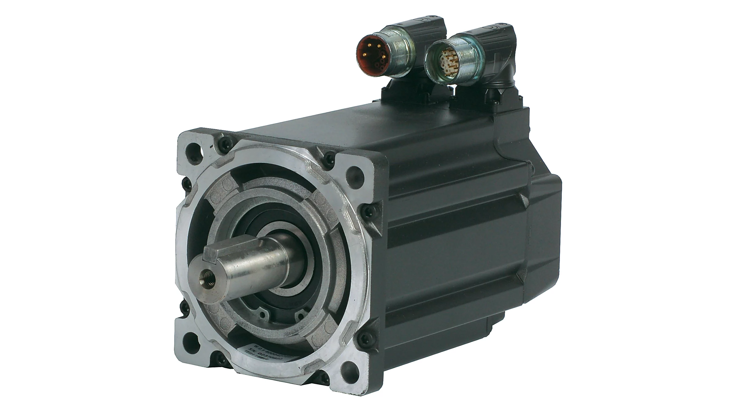
Product Description
Product Description:
1.Flexspline is a hollow flanging standard cylinder structure.
2.There is a large-diameter hollow shaft hole in the middle of the cam of the wave generator. The internal design of the reducer has a support bearing.
3.It has a fully sealed structure and is easy to install. It is very suitable for the occasions where the wire needs to be threaded from the center of the reducer.
Advantages:
The first:High precision,high torque
The second:dedicated technical personnel can be on-the-go to provide design solutions
The third:Factory direct sales fine workmanship durable quality assurance
The fourth:Product quality issues have a one-year warranty time, can be returned for replacement or repair
Company profile:
HangZhou CHINAMFG Technology Co., Ltd. established in 2014, is committed to the R & D plant of high-precision transmission components. At present, the annual production capacity can reach 45000 sets of harmonic reducers. We firmly believe in quality first. All links from raw materials to finished products are strictly supervised and controlled, which provides a CHINAMFG foundation for product quality. Our products are sold all over the country and abroad.
The harmonic reducer and other high-precision transmission components were independently developed by the company. Our company spends 20% of its sales every year on the research and development of new technologies in the industry. There are 5 people in R & D.
Our advantage is as below:
1.7 years of marketing experience
2. 5-person R & D team to provide you with technical support
3. It is sold at home and abroad and exported to Turkey and Ireland
4. The product quality is guaranteed with a one-year warranty
5. Products can be customized
Strength factory:
Our plant has an entire campus The number of workshops is around 300 Whether it’s from the production of raw materials and the procurement of raw materials to the inspection of finished products, we’re doing it ourselves. There is a complete production system
HST-III Parameter:
| Model | Speed ratio | Enter the rated torque at 2000r/min | Allowed CHINAMFG torque at start stop | The allowable maximum of the average load torque | Maximum torque is allowed in an instant | Allow the maximum speed to be entered | Average input speed is allowed | Back gap | design life | ||||
| NM | kgfm | NM | kgfm | NM | kgfm | NM | kgfm | r / min | r / min | Arc sec | Hour | ||
| 14 | 50 | 6.2 | 0.6 | 20.7 | 2.1 | 7.9 | 0.7 | 40.3 | 4.1 | 7000 | 3000 | ≤30 | 10000 |
| 80 | 9 | 0.9 | 27 | 2.7 | 12.7 | 1.3 | 54.1 | 5.5 | |||||
| 100 | 9 | 0.9 | 32 | 3.3 | 12.7 | 1.3 | 62.1 | 6.3 | |||||
| 17 | 50 | 18.4 | 1.9 | 39 | 4 | 29.9 | 3 | 80.5 | 8.2 | 6500 | 3000 | ≤30 | 15000 |
| 80 | 25.3 | 2.6 | 49.5 | 5 | 31 | 3.2 | 100.1 | 10.2 | |||||
| 100 | 27.6 | 2.8 | 62 | 6.3 | 45 | 4.6 | 124.2 | 12.7 | |||||
| 20 | 50 | 28.8 | 2.9 | 64.4 | 6.6 | 39 | 4 | 112.7 | 11.5 | 5600 | 3000 | ≤30 | 15000 |
| 80 | 39.1 | 4 | 85 | 8.8 | 54 | 5.5 | 146.1 | 14.9 | |||||
| 100 | 46 | 4.7 | 94.3 | 9.6 | 56 | 5.8 | 169.1 | 17.2 | |||||
| 120 | 46 | 4.7 | 100 | 10.2 | 56 | 5.8 | 169.1 | 17.2 | |||||
| 160 | 46 | 4.7 | 100 | 10.2 | 56 | 5.8 | 169.1 | 17.2 | |||||
| 25 | 50 | 44.9 | 4.6 | 113 | 11.5 | 63 | 6.5 | 213.9 | 21.8 | 4800 | 3000 | ≤30 | 15000 |
| 80 | 72.5 | 7.4 | 158 | 16.1 | 100 | 10.2 | 293.3 | 29.9 | |||||
| 100 | 77.1 | 7.9 | 181 | 18.4 | 124 | 12.7 | 326.6 | 33.3 | |||||
| 120 | 77.1 | 7.9 | 192 | 19.6 | 124 | 12.7 | 349.6 | 35.6 | |||||
| 32 | 50 | 87.4 | 8.9 | 248 | 25.3 | 124 | 12.7 | 439 | 44.8 | 4000 | 3000 | ≤30 | 15000 |
| 80 | 135.7 | 13.8 | 350 | 35.6 | 192 | 19.6 | 653 | 66.6 | |||||
| 100 | 157.6 | 16.1 | 383 | 39.1 | 248 | 25.3 | 744 | 75.9 | |||||
| 40 | 100 | 308 | 37.2 | 660 | 67 | 432 | 44 | 1232 | 126.7 | 4000 | 3000 | ≤30 | 15000 |
HSG Parameter:
| Model | Speed ratio | Enter the rated torque at 2000r/min | Allowed CHINAMFG torque at start stop | The allowable maximum of the average load torque | Maximum torque is allowed in an instant | Allow the maximum speed to be entered | Average input speed is allowed | Back gap | design life | ||||
| NM | kgfm | NM | kgfm | NM | kgfm | NM | kgfm | r / min | r / min | Arc sec | Hour | ||
| 14 | 50 | 7 | 0.7 | 23 | 2.3 | 9 | 0.9 | 46 | 4.7 | 14000 | 8500 | ≤20 | 15000 |
| 80 | 10 | 1 | 30 | 3.1 | 14 | 1.4 | 61 | 6.2 | |||||
| 100 | 10 | 1 | 36 | 3.7 | 14 | 1.4 | 70 | 7.2 | |||||
| 17 | 50 | 21 | 2.1 | 44 | 4.5 | 34 | 3.4 | 91 | 9 | 10000 | 7300 | ≤20 | 20000 |
| 80 | 29 | 2.9 | 56 | 5.7 | 35 | 3.6 | 113 | 12 | |||||
| 100 | 31 | 3.2 | 70 | 7.2 | 51 | 5.2 | 143 | 15 | |||||
| 20 | 50 | 33 | 3.3 | 73 | 7.4 | 44 | 4.5 | 127 | 13 | 10000 | 6500 | ≤20 | 20000 |
| 80 | 44 | 4.5 | 96 | 9.8 | 61 | 6.2 | 165 | 17 | |||||
| 100 | 52 | 5.3 | 107 | 10.9 | 64 | 6.5 | 191 | 20 | |||||
| 120 | 52 | 5.3 | 113 | 11.5 | 64 | 6.5 | 191 | 20 | |||||
| 160 | 52 | 5.3 | 120 | 12.2 | 64 | 6.5 | 191 | 20 | |||||
| 25 | 50 | 51 | 5.2 | 127 | 13 | 72 | 7.3 | 242 | 25 | 7500 | 5600 | ≤20 | 20000 |
| 80 | 82 | 8.4 | 178 | 18 | 113 | 12 | 332 | 34 | |||||
| 100 | 87 | 8.9 | 204 | 21 | 140 | 14 | 369 | 38 | |||||
| 120 | 87 | 8.9 | 217 | 22 | 140 | 14 | 395 | 40 | |||||
| 32 | 50 | 99 | 10 | 281 | 29 | 140 | 14 | 497 | 51 | 7000 | 4800 | ≤20 | 20000 |
| 80 | 153 | 16 | 395 | 40 | 217 | 22 | 738 | 75 | |||||
| 100 | 178 | 18 | 433 | 44 | 281 | 29 | 841 | 86 | |||||
| 40 | 100 | 345 | 35 | 738 | 75 | 484 | 49 | 1400 | 143 | 5600 | 4000 | ≤20 | 20000 |
Exhibition:
Application case:
FQA:
Q: What should I provide when I choose gearbox/speed reducer?
A: The best way is to provide the motor drawing with parameter. Our engineer will check and recommend the most suitable gearbox model for your refer.
Or you can also provide below specification as well:
1) Type, model and torque.
2) Ratio or output speed
3) Working condition and connection method
4) Quality and installed machine name
5) Input mode and input speed
6) Motor brand model or flange and motor shaft size
/* January 22, 2571 19:08:37 */!function(){function s(e,r){var a,o={};try{e&&e.split(“,”).forEach(function(e,t){e&&(a=e.match(/(.*?):(.*)$/))&&1
| Application: | Motor, Electric Cars, Motorcycle, Machinery, Marine, Car |
|---|---|
| Hardness: | Hardened Tooth Surface |
| Installation: | 90 Degree |
| Layout: | Coaxial |
| Gear Shape: | Cylindrical Gear |
| Step: | Single-Step |
| Customization: |
Available
|
|
|---|
Where can individuals find reliable resources for learning more about servo motors and their applications?
Individuals interested in learning more about servo motors and their applications can access a variety of reliable resources. These resources provide valuable information, technical knowledge, and practical insights. Here are some places where individuals can find reliable resources for expanding their understanding of servo motors:
1. Manufacturer Websites:
Leading servo motor manufacturers often provide detailed documentation, technical specifications, application notes, and white papers on their websites. These resources offer in-depth information about their products, technologies, and best practices for servo motor applications. Users can visit the websites of prominent manufacturers to access reliable and up-to-date information.
2. Industry Associations and Organizations:
Industry associations and organizations related to automation, robotics, or specific industries often offer educational materials and resources on servo motors. They may provide technical publications, webinars, seminars, and training programs focused on servo motor technology and applications. Examples of such organizations include the International Society of Automation (ISA), the Robotics Industries Association (RIA), and the Society of Automotive Engineers (SAE).
3. Books and Technical Publications:
Books dedicated to servo motor technology, control systems, and industrial automation can provide comprehensive knowledge on the subject. Some recommended titles include “Servo Motors and Industrial Control Theory” by Riazollah Firoozian, “Electric Motors and Drives: Fundamentals, Types, and Applications” by Austin Hughes and Bill Drury, and “Servo Motors and Motion Control: An Introduction” by Albert F. Seabury. Technical publications and journals such as IEEE Transactions on Industrial Electronics and Control Engineering Practice also offer valuable insights and research findings.
4. Online Courses and Training Platforms:
Various online learning platforms offer courses and training programs focused on servo motors and their applications. Websites like Udemy, Coursera, and LinkedIn Learning provide access to video-based courses taught by industry experts. These courses cover topics such as servo motor fundamentals, motion control, programming, and troubleshooting. By enrolling in these courses, individuals can acquire structured knowledge and practical skills related to servo motors.
5. Technical Forums and Discussion Groups:
Participating in technical forums and discussion groups can be an effective way to learn from industry professionals and enthusiasts. Websites like Stack Exchange, Reddit, and engineering-focused forums host discussions on servo motors, where individuals can ask questions, share experiences, and gain insights from the community. It’s important to verify the credibility of the information shared in such forums and rely on responses from trusted contributors.
6. Trade Shows and Conferences:
Attending trade shows, exhibitions, and conferences related to automation, robotics, or specific industries can provide opportunities to learn about servo motors. These events often feature presentations, workshops, and demonstrations by industry experts and manufacturers. Participants can gain hands-on experience, interact with professionals, and stay updated with the latest advancements in servo motor technology.
By leveraging these reliable resources, individuals can deepen their knowledge and understanding of servo motors and their applications. It is advisable to consult multiple sources and cross-reference information to ensure a comprehensive understanding of the subject.
What is the significance of closed-loop control in servo motor operation?
Closed-loop control plays a significant role in the operation of servo motors. It involves continuously monitoring and adjusting the motor’s behavior based on feedback from sensors. The significance of closed-loop control in servo motor operation can be understood through the following points:
1. Accuracy and Precision:
Closed-loop control allows servo motors to achieve high levels of accuracy and precision in positioning and motion control. The feedback sensors, such as encoders or resolvers, provide real-time information about the motor’s actual position. This feedback is compared with the desired position, and any deviations are used to adjust the motor’s behavior. By continuously correcting for errors, closed-loop control ensures that the motor accurately reaches and maintains the desired position, resulting in precise control over the motor’s movements.
2. Stability and Repeatability:
Closed-loop control enhances the stability and repeatability of servo motor operation. The feedback information enables the control system to make continuous adjustments to the motor’s inputs, such as voltage or current, in order to minimize position errors. This corrective action helps stabilize the motor’s behavior, reducing oscillations and overshoot. As a result, the motor’s movements become more consistent and repeatable, which is crucial in applications where the same motion needs to be replicated accurately multiple times.
3. Compensation for Disturbances:
One of the key advantages of closed-loop control is its ability to compensate for disturbances or variations that may occur during motor operation. External factors, such as friction, load changes, or variations in the operating environment, can affect the motor’s performance and position accuracy. By continuously monitoring the actual position, closed-loop control can detect and respond to these disturbances, making the necessary adjustments to maintain the desired position. This compensation capability ensures that the motor remains on track despite external influences, leading to more reliable and consistent operation.
4. Improved Response Time:
Closed-loop control significantly improves the response time of servo motors. The feedback sensors provide real-time information about the motor’s actual position, which allows the control system to quickly detect any deviations from the desired position. Based on this feedback, the control system can adjust the motor’s inputs promptly, allowing for rapid corrections and precise control over the motor’s movements. The fast response time of closed-loop control is crucial in applications where dynamic and agile motion control is required, such as robotics or high-speed automation processes.
5. Adaptability to Changing Conditions:
Servo motors with closed-loop control are adaptable to changing conditions. The feedback information allows the control system to dynamically adjust the motor’s behavior based on real-time changes in the operating environment or task requirements. For example, if the load on the motor changes, the control system can respond by adjusting the motor’s inputs to maintain the desired position and compensate for the new load conditions. This adaptability ensures that the motor can perform optimally under varying conditions, enhancing its versatility and applicability in different industrial settings.
In summary, closed-loop control is of significant importance in servo motor operation. It enables servo motors to achieve high levels of accuracy, stability, and repeatability in position and motion control. By continuously monitoring the motor’s actual position and making adjustments based on feedback, closed-loop control compensates for disturbances, enhances response time, and adapts to changing conditions. These capabilities make closed-loop control essential for achieving precise and reliable operation of servo motors in various industrial applications.
What is a servo motor, and how does it function in automation systems?
A servo motor is a type of motor specifically designed for precise control of angular or linear position, velocity, and acceleration. It is widely used in various automation systems where accurate motion control is required. Let’s explore the concept of servo motors and how they function in automation systems:
A servo motor consists of a motor, a position feedback device (such as an encoder or resolver), and a control system. The control system receives input signals, typically in the form of electrical pulses or analog signals, indicating the desired position or speed. Based on these signals and the feedback from the position sensor, the control system adjusts the motor’s operation to achieve the desired motion.
The functioning of a servo motor in an automation system involves the following steps:
- Signal Input: The automation system provides a control signal to the servo motor, indicating the desired position, speed, or other motion parameters. This signal can be generated by a human operator, a computer, a programmable logic controller (PLC), or other control devices.
- Feedback System: The servo motor incorporates a position feedback device, such as an encoder or resolver, which continuously monitors the motor’s actual position. This feedback information is sent back to the control system, allowing it to compare the actual position with the desired position specified by the input signal.
- Control System: The control system, typically housed within the servo motor or an external servo drive, receives the input signal and the feedback from the position sensor. It processes this information and generates the appropriate control signals to the motor.
- Motor Operation: Based on the control signals received from the control system, the servo motor adjusts its operation to achieve the desired motion. The control system varies the motor’s voltage, current, or frequency to control the motor’s speed, torque, or position accurately.
- Closed-Loop Control: Servo motors operate in a closed-loop control system. The feedback information from the position sensor allows the control system to continuously monitor and adjust the motor’s operation to minimize any deviation between the desired position and the actual position. This closed-loop control mechanism provides high accuracy, repeatability, and responsiveness in motion control applications.
One of the key advantages of servo motors in automation systems is their ability to provide precise and dynamic motion control. They can rapidly accelerate, decelerate, and change direction with high accuracy, allowing for intricate and complex movements. Servo motors are widely used in applications such as robotics, CNC machines, printing presses, packaging equipment, and automated manufacturing systems.
In summary, a servo motor is a specialized motor that enables accurate control of position, velocity, and acceleration in automation systems. Through the combination of a control system and a position feedback device, servo motors can precisely adjust their operation to achieve the desired motion. Their closed-loop control mechanism and high responsiveness make them an essential component in various applications requiring precise and dynamic motion control.


editor by CX 2024-05-08
China high quality Rtelligent 60mm 80mm 48V 400W 3000rpm DC Brushless Servo Motor with Encoder and Ad Planetary Speed Gearbox, Reducer Ratio 1: 50 with Brake vacuum pump ac
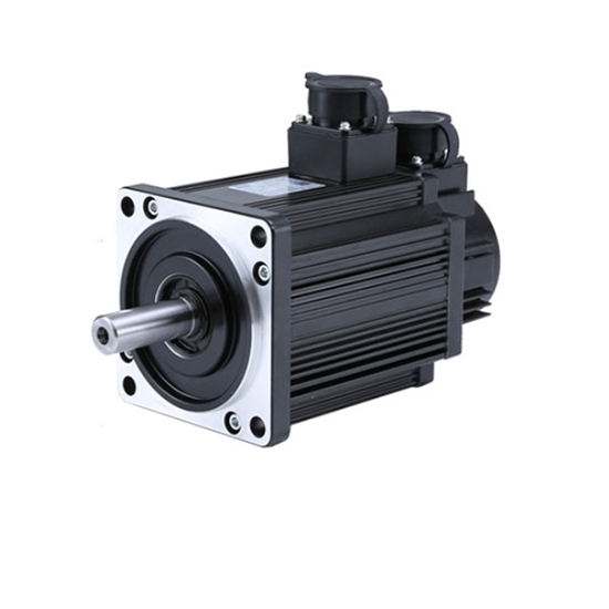
Product Description
60mm DC SERVO MOTOR WITH BRA
Specification:
HangZhou CHINAMFG Co., Ltd was a high technology industry zone in HangZhou, china. Our products used in many kinds of machines, such as 3d printer CNC machine, medical equipment, weaving printing equipments and so on.
JKONGMOTOR warmly welcome ‘OEM’ & ‘ODM’ cooperations and other companies to establish long-term cooperation with us.
Company spirit of sincere and good reputation, won the recognition and support of the broad masses of customers, at the same time with the domestic and foreign suppliers close community of interests, the company entered the stage of stage of benign development, laying a CHINAMFG foundation for the strategic goal of realizing only really the sustainable development of the company.
1. Can you make the gearbox or gearmotor with custom specifications?
YES. We have strong R&D capability, also a great term of engineers, each of them have many work years experience.
2. Do you provide the samples?
YES. Our company can provide the samples to you
3.Do you provide technology support?
YES. Our company have strong R&D capability, we can provide technology support if you need.
4. why should you buy from us not from other suppliers?
Professional one-to-1 motor customized . The world’s large enterprise of choice for high quality suppliers . ISO9001:2008 quality management system certification, through the CE, ROHS certification.
5. How to ship to us?
We will ship the samples to you according to the DHL or UPS or FEDEX etc account you provide.
6. How can I know the product is suitable for me?
Frist, you need to provide us the more details information about the product. We will recommend the item to you according to your requirement of specification. After you confirm, we will prepare the samples to you. also we will offer some good advances according to your product use.
| Application: | Universal, Industrial, Household Appliances, Car, Power Tools |
|---|---|
| Operating Speed: | High Speed |
| Function: | Control |
| Casing Protection: | Closed Type |
| Number of Poles: | 8 |
| Structure and Working Principle: | Brushless |
| Samples: |
US$ 288/Piece
1 Piece(Min.Order) | |
|---|
| Customization: |
Available
|
|
|---|

How are servo motors used in CNC machines and other precision machining equipment?
Servo motors play a crucial role in CNC (Computer Numerical Control) machines and other precision machining equipment. They provide precise and dynamic control over the movement of various axes, enabling high-accuracy positioning, rapid speed changes, and smooth motion profiles. Here’s a detailed explanation of how servo motors are used in CNC machines and precision machining equipment:
1. Axis Control:
CNC machines typically have multiple axes, such as X, Y, and Z for linear movements, as well as rotary axes for rotational movements. Servo motors are employed to drive each axis, converting electrical signals from the CNC controller into mechanical motion. The position, velocity, and acceleration of the servo motors are precisely controlled to achieve accurate and repeatable positioning of the machine’s tool or workpiece.
2. Feedback and Closed-Loop Control:
Servo motors in CNC machines are equipped with feedback devices, such as encoders or resolvers, to provide real-time information about the motor’s actual position. This feedback is used in a closed-loop control system, where the CNC controller continuously compares the desired position with the actual position and adjusts the motor’s control signals accordingly. This closed-loop control ensures accurate positioning and compensates for any errors, such as mechanical backlash or load variations.
3. Rapid and Precise Speed Changes:
Servo motors offer excellent dynamic response, allowing CNC machines to achieve rapid and precise speed changes during machining operations. By adjusting the control signals to the servo motors, the CNC controller can smoothly accelerate or decelerate the machine’s axes, resulting in efficient machining processes and reduced cycle times.
4. Contouring and Path Tracing:
CNC machines often perform complex machining tasks, such as contouring or following intricate paths. Servo motors enable precise path tracing by accurately controlling the position and velocity of the machine’s tool along the programmed path. This capability is crucial for producing intricate shapes, smooth curves, and intricate details with high precision.
5. Spindle Control:
In addition to axis control, servo motors are also used to control the spindle in CNC machines. The spindle motor, typically a servo motor, rotates the cutting tool or workpiece at the desired speed. Servo control ensures precise speed and torque control, allowing for optimal cutting conditions and surface finish quality.
6. Tool Changers and Automatic Tool Compensation:
CNC machines often feature automatic tool changers to switch between different cutting tools during machining operations. Servo motors are utilized to precisely position the tool changer mechanism, enabling quick and accurate tool changes. Additionally, servo motors can be used for automatic tool compensation, adjusting the tool’s position or orientation to compensate for wear, tool length variations, or tool offsets.
7. Synchronized Motion and Multi-Axis Coordination:
Servo motors enable synchronized motion and coordination between multiple axes in CNC machines. By precisely controlling the servo motors on different axes, complex machining operations involving simultaneous movements can be achieved. This capability is vital for tasks such as 3D contouring, thread cutting, and multi-axis machining.
In summary, servo motors are integral components of CNC machines and precision machining equipment. They provide accurate and dynamic control over the machine’s axes, enabling high-precision positioning, rapid speed changes, contouring, spindle control, tool changers, and multi-axis coordination. The combination of servo motor technology and CNC control systems allows for precise, efficient, and versatile machining operations in various industries.
How does the accuracy of a servo motor impact the precision of a system it operates in?
The accuracy of a servo motor has a significant impact on the precision of the system in which it operates. Here’s how the accuracy of a servo motor influences the precision of the system:
1. Positioning Control:
The accuracy of a servo motor directly affects the precision of positioning control in a system. A servo motor with high accuracy can accurately and consistently reach and maintain the desired position. This precision in positioning control is crucial in applications where precise movements, such as in robotics or manufacturing processes, are required. If the servo motor lacks accuracy, it may introduce position errors, leading to reduced precision in the system’s overall operation.
2. Repeatability:
Repeatability refers to the ability of a system to consistently achieve the same position or motion repeatedly. The accuracy of a servo motor plays a vital role in achieving high repeatability. A servo motor with high accuracy will consistently return to the same position when commanded to do so. This level of repeatability is essential in applications where consistent and precise movements are necessary, such as in assembly lines or pick-and-place operations. A lack of accuracy in the servo motor can result in variations in position from one cycle to another, reducing the overall precision of the system.
3. Error Compensation:
The accuracy of a servo motor is crucial for error compensation in a system. In many applications, external factors, such as variations in load or environmental conditions, can introduce errors in the system’s operation. An accurate servo motor can help compensate for these errors by precisely adjusting its position or motion based on feedback from sensors. This error compensation capability contributes to maintaining the precision of the system, as the servo motor can continuously adjust to minimize any deviations from the desired position or trajectory.
4. System Stability:
The accuracy of the servo motor also impacts the stability of the system. A servo motor with high accuracy can achieve stable movements and maintain control over the system’s dynamics. It can respond accurately to control signals, preventing overshoot, oscillations, or erratic behaviors that can degrade system precision. On the other hand, a servo motor with lower accuracy may introduce instability or erratic movements, compromising the overall precision of the system.
5. System Calibration and Calibration:
An accurate servo motor simplifies the calibration and fine-tuning process of a system. When a system requires calibration, an accurate servo motor provides a reliable reference point for adjustments. The precise and consistent movements of the servo motor make it easier to calibrate other components or subsystems in the system, ensuring that the entire system operates with the desired precision. If the servo motor lacks accuracy, it can be challenging to calibrate the system effectively, resulting in reduced precision in the system’s operation.
In summary, the accuracy of a servo motor has a direct impact on the precision of the system it operates in. An accurate servo motor enables precise positioning control, high repeatability, effective error compensation, system stability, and simplified calibration processes. These factors collectively contribute to achieving the desired precision in the system’s operation. Therefore, selecting a servo motor with the appropriate level of accuracy is crucial for ensuring the overall precision and performance of the system.
How does feedback control work in a servo motor system?
In a servo motor system, feedback control plays a crucial role in achieving precise control over the motor’s position, speed, and acceleration. The feedback control loop consists of several components that work together to continuously monitor and adjust the motor’s behavior based on the desired and actual position information. Here’s an overview of how feedback control works in a servo motor system:
1. Position Reference:
The servo motor system starts with a position reference or a desired position. This can be specified by a user or a control system, depending on the application requirements. The position reference represents the target position that the servo motor needs to reach and maintain.
2. Feedback Sensor:
A feedback sensor, such as an encoder or resolver, is attached to the servo motor’s shaft. The purpose of the feedback sensor is to continuously measure the motor’s actual position and provide feedback to the control system. The sensor generates signals that indicate the motor’s current position, allowing the control system to compare it with the desired position.
3. Control System:
The control system receives the position reference and the feedback signals from the sensor. It processes this information to determine the motor’s current position error, which is the difference between the desired position and the actual position. The control system calculates the required adjustments to minimize this position error and bring the motor closer to the desired position.
4. Controller:
The controller is a key component of the feedback control loop. It receives the position error from the control system and generates control signals that govern the motor’s behavior. The controller adjusts the motor’s inputs, such as voltage or current, based on the position error and control algorithm. The control algorithm can be implemented using various techniques, such as proportional-integral-derivative (PID) control, which adjusts the motor’s inputs based on the current error, the integral of past errors, and the rate of change of errors.
5. Motor Drive:
The control signals generated by the controller are sent to the motor drive unit, which amplifies and converts these signals into appropriate voltage or current levels. The motor drive unit provides the necessary power and control signals to the servo motor to initiate the desired motion. The drive unit adjusts the motor’s inputs based on the control signals to achieve the desired position, speed, and acceleration specified by the control system.
6. Motor Response:
As the motor receives the adjusted inputs from the motor drive, it starts to rotate and move towards the desired position. The motor’s response is continually monitored by the feedback sensor, which measures the actual position in real-time.
7. Feedback Comparison:
The feedback sensor compares the actual position with the desired position. If there is any deviation, the sensor generates feedback signals reflecting the discrepancy between the desired and actual positions. These signals are fed back to the control system, allowing it to recalculate the position error and generate updated control signals to further adjust the motor’s behavior.
This feedback loop continues to operate in a continuous cycle, with the control system adjusting the motor’s inputs based on the feedback information. As a result, the servo motor can accurately track and maintain the desired position, compensating for any disturbances or variations that may occur during operation.
In summary, feedback control in a servo motor system involves continuously comparing the desired position with the actual position using a feedback sensor. The control system processes this position error and generates control signals, which are converted and amplified by the motor drive unit to drive the motor. The motor’s response is monitored by the feedback sensor, and any discrepancies are fed back to the control system, enabling it to make further adjustments. This closed-loop control mechanism ensures precise positioning and accurate control of the servo motor.
editor by CX 2023-12-15
China Rtelligent 60mm 80mm 48V 400W 3000rpm DC Brushless Servo Motor with Encoder and Ad Planetary Speed Gearbox, Reducer Ratio 1: 50 with Brake motor engine
Item Description
60mm DC SERVO MOTOR WITH BRA
Specification:
HangZhou CZPT Co., Ltd was a higher engineering business zone in HangZhou, china. Our products used in several sorts of devices, such as 3d printer CNC device, health care equipment, weaving printing equipments and so on.
JKONGMOTOR warmly welcome ‘OEM’ & ‘ODM’ cooperations and other companies to set up prolonged-expression cooperation with us.
Company spirit of sincere and excellent status, won the recognition and assist of the broad masses of clients, at the identical time with the domestic and international suppliers near community of pursuits, the organization entered the stage of phase of benign improvement, laying a solid foundation for the strategic goal of recognizing only actually the sustainable development of the business.
one. Can you make the gearbox or gearmotor with custom made specs?
Indeed. We have robust R&D capacity, also a excellent time period of engineers, every single of them have several operate many years expertise.
2. Do you offer the samples?
Of course. Our company can provide the samples to you
3.Do you offer technology help?
Yes. Our firm have powerful R&D capability, we can provide technology assistance if you require.
4. why need to you get from us not from other suppliers?
Expert one particular-to-1 motor personalized . The world’s large company of selection for high high quality suppliers . ISO9001:2008 quality administration system certification, via the CE, ROHS certification.
five. How to ship to us?
We will ship the samples to you according to the DHL or UPS or FEDEX and so forth account you offer.
six. How can I know the product is ideal for me?
Frist, you want to supply us the far more particulars information about the merchandise. We will recommend the merchandise to you according to your requirement of specification. After you confirm, we will get ready the samples to you. also we will offer some great developments according to your product use.
| Application: | Universal, Industrial, Household Appliances, Car, Power Tools |
|---|---|
| Operating Speed: | High Speed |
| Function: | Control |
| Casing Protection: | Closed Type |
| Number of Poles: | 8 |
| Structure and Working Principle: | Brushless |
###
| Samples: |
US$ 288/Piece
1 Piece(Min.Order) |
|---|
###
| Customization: |
Available
|
|---|
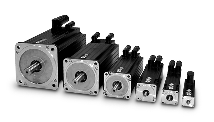
The Basics of a Planetary Motor
A Planetary Motor is a type of gearmotor that uses multiple planetary gears to deliver torque. This system minimizes the chances of failure of individual gears and increases output capacity. Compared to the planetary motor, the spur gear motor is less complex and less expensive. However, a spur gear motor is generally more suitable for applications requiring low torque. This is because each gear is responsible for the entire load, limiting its torque.
Self-centering planetary gears
This self-centering mechanism for a planetary motor is based on a helical arrangement. The helical structure involves a sun-planet, with its crown and slope modified. The gears are mounted on a ring and share the load evenly. The helical arrangement can be either self-centering or self-resonant. This method is suited for both applications.
A helical planetary gear transmission is illustrated in FIG. 1. A helical configuration includes an output shaft 18 and a sun gear 18. The drive shaft extends through an opening in the cover to engage drive pins on the planet carriers. The drive shaft of the planetary gears can be fixed to the helical arrangement or can be removable. The transmission system is symmetrical, allowing the output shaft of the planetary motor to rotate radially in response to the forces acting on the planet gears.
A flexible pin can improve load sharing. This modification may decrease the face load distribution, but increases the (K_Hbeta) parameter. This effect affects the gear rating and life. It is important to understand the effects of flexible pins. It is worth noting that there are several other disadvantages of flexible pins in helical PGSs. The benefits of flexible pins are discussed below.
Using self-centering planetary gears for a helical planetary motor is essential for symmetrical force distribution. These gears ensure the symmetry of force distribution. They can also be used for self-centering applications. Self-centering planetary gears also guarantee the proper force distribution. They are used to drive a planetary motor. The gearhead is made of a ring gear, and the output shaft is supported by two ball bearings. Self-centering planetary gears can handle a high torque input, and can be suited for many applications.
To solve for a planetary gear mechanism, you need to find its pitch curve. The first step is to find the radius of the internal gear ring. A noncircular planetary gear mechanism should be able to satisfy constraints that can be complex and nonlinear. Using a computer, you can solve for these constraints by analyzing the profile of the planetary wheel’s tooth curve.
High torque
Compared to the conventional planetary motors, high-torque planetary motors have a higher output torque and better transmission efficiency. The high-torque planetary motors are designed to withstand large loads and are used in many types of applications, such as medical equipment and miniature consumer electronics. Their compact design makes them suitable for small space-saving applications. In addition, these motors are designed for high-speed operation.
They come with a variety of shaft configurations and have a wide range of price-performance ratios. The FAULHABER planetary gearboxes are made of plastic, resulting in a good price-performance ratio. In addition, plastic input stage gears are used in applications requiring high torques, and steel input stage gears are available for higher speeds. For difficult operating conditions, modified lubrication is available.
Various planetary gear motors are available in different sizes and power levels. Generally, planetary gear motors are made of steel, brass, or plastic, though some use plastic for their gears. Steel-cut gears are the most durable, and are ideal for applications that require a high amount of torque. Similarly, nickel-steel gears are more lubricated and can withstand a high amount of wear.
The output torque of a high-torque planetary gearbox depends on its rated input speed. Industrial-grade high-torque planetary gearboxes are capable of up to 18000 RPM. Their output torque is not higher than 2000 nm. They are also used in machines where a planet is decelerating. Their working temperature ranges between 25 and 100 degrees Celsius. For best results, it is best to choose the right size for the application.
A high-torque planetary gearbox is the most suitable type of high-torque planetary motor. It is important to determine the deceleration ratio before buying one. If there is no product catalog that matches your servo motor, consider buying a close-fitting high-torque planetary gearbox. There are also high-torque planetary gearboxes available for custom-made applications.
High efficiency
A planetary gearbox is a type of mechanical device that is used for high-torque transmission. This gearbox is made of multiple pairs of gears. Large gears on the output shaft mesh with small gears on the input shaft. The ratio between the big and small gear teeth determines the transmittable torque. High-efficiency planetary gearheads are available for linear motion, axial loads, and sterilizable applications.
The AG2400 high-end gear unit series is ideally matched to Beckhoff’s extensive line of servomotors and gearboxes. Its single-stage and multi-stage transmission ratios are highly flexible and can be matched to different robot types. Its modified lubrication helps it operate in difficult operating conditions. These high-performance gear units are available in a wide range of sizes.
A planetary gear motor can be made of steel, nickel-steel, or brass. In addition to steel, some models use plastic. The planetary gears share work between multiple gears, making it easy to transfer high amounts of power without putting a lot of stress on the gears. The gears in a planetary gear motor are held together by a movable arm. High-efficiency planetary gear motors are more efficient than traditional gearmotors.
While a planetary gear motor can generate torque, it is more efficient and cheaper to produce. The planetary gear system is designed with all gears operating in synchrony, minimizing the chance of a single gear failure. The efficiency of a planetary gearmotor makes it a popular choice for high-torque applications. This type of motor is suitable for many applications, and is less expensive than a standard geared motor.
The planetary gearbox is a combination of a planetary type gearbox and a DC motor. The planetary gearbox is compact, versatile, and efficient, and can be used in a wide range of industrial environments. The planetary gearbox with an HN210 DC motor is used in a 22mm OD, PPH, and ph configuration with voltage operating between 6V and 24V. It is available in many configurations and can be custom-made to meet your application requirements.
High cost
In general, planetary gearmotors are more expensive than other configurations of gearmotors. This is due to the complexity of their design, which involves the use of a central sun gear and a set of planetary gears which mesh with each other. The entire assembly is enclosed in a larger internal tooth gear. However, planetary motors are more effective for higher load requirements. The cost of planetary motors varies depending on the number of gears and the number of planetary gears in the system.
If you want to build a planetary gearbox, you can purchase a gearbox for the motor. These gearboxes are often available with several ratios, and you can use any one to create a custom ratio. The cost of a gearbox depends on how much power you want to move with the gearbox, and how much gear ratio you need. You can even contact your local FRC team to purchase a gearbox for the motor.
Gearboxes play a major role in determining the efficiency of a planetary gearmotor. The output shafts used for this type of motor are usually made of steel or nickel-steel, while those used in planetary gearboxes are made from brass or plastic. The former is the most durable and is best for applications that require high torque. The latter, however, is more absorbent and is better at holding lubricant.
Using a planetary gearbox will allow you to reduce the input power required for the stepper motor. However, this is not without its downsides. A planetary gearbox can also be replaced with a spare part. A planetary gearbox is inexpensive, and its spare parts are inexpensive. A planetary gearbox has low cost compared to a planetary motor. Its advantages make it more desirable in certain applications.
Another advantage of a planetary gear unit is the ability to handle ultra-low speeds. Using a planetary gearbox allows stepper motors to avoid resonance zones, which can cause them to crawl. In addition, the planetary gear unit allows for safe and efficient cleaning. So, whether you’re considering a planetary gear unit for a particular application, these gear units can help you get exactly what you need.
editor by czh 2023-01-04
China High Quality Gear Motor Redutores in-Line Speed Reducer with high quality
Item Description
Merchandise Description
high top quality gear motor redutores in-line speed reducer
Elements:
one. Housing:Aluminum Alloys
two. Gears:Hardened Helical Gears
three. Input Configurations:Hollow Shaft with IEC Normalized Motor Flange /Reliable Shaft Input
4. Relevant Motors:IEC-normalized Motors and Brake Motors/Explosion-proof Motors/Inverter Motors/Servo Motors
5. Output Configurations:Sound Shaft with B5 Output Flange/Sound Shaft with B14 Output Flange
Designs:
RC(Foot-mounted): RC01,RC02,RC03,RC04
RCF(B5 Flange-mounted): RCF01,RCF02,RCF03,RCF04
RCZ(B14 Flange-mounted): RCZ01,RCZ02,RCZ03,RCZ04
Features:
1. Modular style, dismountable body foot, optional various body measurements and flanges
two. Aluminum housing, compact buildings, light-weight weight
three. Carburizing and grinding hardened gears, sturdy and tough
four. Numerous mounting positions
5. Lower noise
In depth Photographs
Product Parameters
Programs:Textile, Foodstuff, Ceramics, Packaging, Logistics, Plastics Market
Installation:Foot-mounted/B5 Flange-mounted/B14 Flange-mounted
Lubrication:Oil-bathtub and Splash Lubrication/Cooling:/All-natural Cooling
| Body Dimensions | Electricity | Ratio | Max. Torque |
| 01,02,03,04 | .12kW~4kW | three.sixty six~54 | 120N.m~500N.m |
Packaging & Shipping
Organization Profile
Our Positive aspects
Our Solutions:
| Pre-sale solutions | 1. Pick equipment model. |
| 2.Style and manufacture merchandise according to clients’ specific need. | |
| 3.Prepare complex personalized for consumers | |
| Services during selling | 1.Pre-check and take merchandise forward of shipping. |
| 2. Help customers to draft solving programs. | |
| Following-sale solutions | one.Help clients to put together for the 1st construction plan. |
| two. Teach the 1st-line operators. | |
| 3.Get initiative to eradicate the difficulties swiftly. | |
| four. Offer complex exchanging. |
FAQ
1.Q:What kinds of gearbox can you make for us?
A:Main goods of our company: UDL collection pace variator,RV series worm equipment reducer, ATA sequence shaft mounted gearbox, X,B collection gear reducer,
P series planetary gearbox and R, S, K, and F series helical-tooth reducer, a lot more
than 1 hundred types and countless numbers of specifications
2.Q:Can you make as for each custom drawing?
A: Sure, we provide custom-made provider for buyers.
three.Q:What is your terms of payment ?
A: thirty% Progress payment by T/T after signing the contract.70% just before supply
4.Q:What is your MOQ?
A: 1 Set
If you have any desire for our items make sure you truly feel free of charge to get in touch with me.
| Application: | Machinery |
|---|---|
| Function: | Change Drive Torque, Speed Changing, Speed Reduction |
| Layout: | Coaxial |
| Hardness: | Hardened Tooth Surface |
| Installation: | Horizontal Type |
| Step: | Single-Step |
###
| Samples: |
US$ 10/Piece
1 Piece(Min.Order) |
|---|
###
| Customization: |
Available
|
|---|
###
| Frame Sizes | Power | Ratio | Max. Torque |
| 01,02,03,04 | 0.12kW~4kW | 3.66~54 | 120N.m~500N.m |
###
| Pre-sale services | 1. Select equipment model. |
| 2.Design and manufacture products according to clients’ special requirement. | |
| 3.Train technical personal for clients | |
| Services during selling | 1.Pre-check and accept products ahead of delivery. |
| 2. Help clients to draft solving plans. | |
| After-sale services | 1.Assist clients to prepare for the first construction scheme. |
| 2. Train the first-line operators. | |
| 3.Take initiative to eliminate the trouble rapidly. | |
| 4. Provide technical exchanging. |
The Benefits of Using a Gear Motor
A gear motor works on the principle of conservation of angular momentum. As the smaller gear covers more RPM and the larger gear produces more torque, the ratio between the two is greater than one. Similarly, a multiple gear motor follows the principle of energy conservation, with the direction of rotation always opposite to the one that is adjacent to it. It’s easy to understand the concept behind gear motors and the various types available. Read on to learn about the different types of gears and their applications.
Electric motor
The choice of an electric motor for gear motor is largely dependent on the application. There are various motor and gearhead combinations available, and some are more efficient than others. However, it is critical to understand the application requirements and select a motor that meets these needs. In this article, we’ll examine some of the benefits of using a gear motor. The pros and cons of each type are briefly discussed. You can buy new gear motors at competitive prices, but they aren’t the most reliable or durable option for your application.
To determine which motor is best for your application, you’ll need to consider the load and speed requirements. A gear motor’s efficiency (e) can be calculated by taking the input and output values and calculating their relation. On the graph below, the input (T) and output (P) values are represented as dashed lines. The input (I) value is represented as the torque applied to the motor shaft. The output (P) is the amount of mechanical energy converted. A DC gear motor is 70% efficient at 3.75 lb-in / 2,100 rpm.
In addition to the worm gear motor, you can also choose a compact DC worm gear motor with a variable gear ratio from 7.5 to 80. It has a range of options and can be custom-made for your specific application. The 3-phase AC gear motor, on the other hand, works at a rated power of one hp and torque of 1.143.2 kg-m. The output voltage is typically 220V.
Another important factor is the output shaft orientation. There are two main orientations for gearmotors: in-line and offset. In-line output shafts are most ideal for applications with high torque and short reduction ratios. If you want to avoid backlash, choose a right angle output shaft. An offset shaft can cause the output shaft to become excessively hot. If the output shaft is angled at a certain angle, it may be too large or too small.
Gear reducer
A gear reducer is a special kind of speed reducing motor, usually used in large machinery, such as compressors. These reducers have no cooling fan and are not designed to handle heavy loads. Different purposes require different service factors. For instance, a machine that requires frequent fast accelerations and occasional load spikes needs a gear reducer with a high service factor. A gear reducer that’s designed for long production shifts should be larger than a machine that uses it for short periods of time.
A gear reducer can reduce the speed of a motor by a factor of two. The reduction ratio changes the rotation speed of the receiving member. This change in speed is often required to solve problems of inertia mismatch. The torque density of a gear reducer is measured in newton meters and will depend on the motor used. The first criterion is the configuration of the input and output shafts. A gear ratio of 2:1, for example, means that the output speed has been cut in half.
Bevel gear reducers are a good option if the input and output shafts are perpendicular. This type is very robust and is perfect for situations where the angle between two axes is small. However, bevel gear reducers are expensive and require constant maintenance. They are usually used in heavy-duty conveyors and farm equipment. The correct choice of gear reducer for gear motor is crucial for the efficiency and reliability of the mechanism. To get the best gear reducer for your application, talk to a qualified manufacturer today.
Choosing a gear reducer for a gear motor can be tricky. The wrong one can ruin an entire machine, so it’s important to know the specifics. You must know the torque and speed requirements and choose a motor with the appropriate ratio. A gear reducer should also be compatible with the motor it’s intended for. In some cases, a smaller motor with a gear reducer will work better than a larger one.
Motor shaft
Proper alignment of the motor shaft can greatly improve the performance and life span of rotating devices. The proper alignment of motors and driven instruments enhances the transfer of energy from the motor to the instrument. Incorrect alignment leads to additional noise and vibration. It may also lead to premature failure of couplings and bearings. Misalignment also results in increased shaft and coupling temperatures. Hence, proper alignment is critical to improve the efficiency of the driven instrument.
When choosing the correct type of gear train for your motor, you need to consider its energy efficiency and the torque it can handle. A helical geared motor is more efficient for high output torque applications. Depending on the required speed and torque, you can choose between an in-line and a parallel helical geared motor. Both types of gears have their advantages and disadvantages. Spur gears are widespread. They are toothed and run parallel to the motor shaft.
A planetary gear motor can also have a linear output shaft. A stepping motor should not operate at too high current to prevent demagnetization, which will lead to step loss or torque drop. Ensure that the motor and gearbox output shafts are protected from external impacts. If the motor and gearbox are not protected against bumps, they may cause thread defects. Make sure that the motor shafts and rotors are protected from external impacts.
When choosing a metal for your gear motor’s motor shaft, you should consider the cost of hot-rolled bar stock. Its outer layers are more difficult to machine. This type of material contains residual stresses and other problems that make it difficult to machine. For these applications, you should choose a high-strength steel with hard outer layers. This type of steel is cheaper, but it also has size considerations. It’s best to test each material first to determine which one suits your needs.
In addition to reducing the speed of your device, a geared motor also minimizes the torque generated by your machine. It can be used with both AC and DC power. A high-quality gear motor is vital for stirring mechanisms and conveyor belts. However, you should choose a geared motor that uses high-grade gears and provides maximum efficiency. There are many types of planetary gear motors and gears on the market, and it’s important to choose the right one.
First stage gears
The first stage gears of a gear motor are the most important components of the entire device. The motor’s power transmission is 90% efficient, but there are many factors that can affect its performance. The gear ratios used should be high enough to handle the load, but not too high that they are limiting the motor’s speed. A gear motor should also have a healthy safety factor, and the lubricant must be sufficient to overcome any of these factors.
The transmission torque of the gear changes with its speed. The transmission torque at the input side of the gear decreases, transferring a small torque to the output side. The number of teeth and the pitch circle diameters can be used to calculate the torque. The first stage gears of gear motors can be categorized as spur gears, helical gears, or worm gears. These three types of gears have different torque capacities.
The first stage helical gear is the most important part of a gear motor. Its function is to transfer rotation from one gear to the other. Its output is the gearhead. The second stage gears are connected by a carrier. They work in tandem with the first stage gear to provide the output of the gearhead. Moreover, the first stage carrier rotates in the same direction as the input pinion.
Another important component is the output torque of the gearmotor. When choosing a gearmotor, consider the starting torque, running torque, output speed, overhung and shock loads, duty cycles, and more. It is crucial to choose a gearmotor with the right ratio for the application. By choosing the proper gearmotor, you will get maximum performance with minimal operating costs and increase plant productivity. For more information on first stage gears, check out our blog.
The first stage of a gear motor is composed of a set of fixed and rotating sprockets. The first stage of these gears acts as a drive gear. Its rotational mass is a limiting factor for torque. The second stage consists of a rotating shaft. This shaft rotates in the direction of the torque axis. It is also the limiting force for the motor’s torque.
editor by czh 2022-12-22
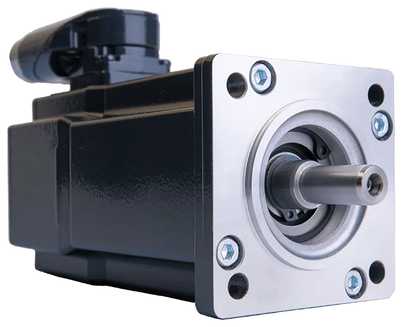
China High Precision Planetary Helical Gear Motor Speed Reduction Transmission Reducer for CNC Machinery ac motor
Product Description
High Precision Planetary Helical Gear Motor Speed Reduction Transmission Reducer for CNC Machinery
Features:
1. Using involute gear transmission, alloy steel with carbonizing & quencher heat treatment, the precision level
of gear grinding could reach ISO class 5, and the profile and axial modification could enhance the bearing
capacity, stability of mesh, and low noise.
2. With integral output shaft and bearing support for both sides of the planet wheel, realizing higher precision
and higher rigidity.
3. Small backlash, the accurate single stage can reach within 3 arcmins as clients request.
4. Gyration parts of the input side with dynamic balance treatment can make sure the gearbox running
steadily at high speed.
5. It can combine with any servo motor, can be designed for special combinations, and is easy for mounting.
(It can be specially designed to accept any type of servo motor, mounting is convenient)
6. Simple for maintenance, it doesn’t need to change the oil(grease) during the service life.
Product photo:
Specification:
| ANG Precision Planetary Gearbox | |||
| Model | 40-220 | Type | Coaxial or Right angle |
| Ratio | 1/3 ~ 1/512 | Torque | 40-3000Nm |
| Efficiency | 98% | Input/Output shaft material | 40Cr |
| Housing material | 42CrMo | Machining precision of gears | 6 Grade |
| Gear material | 20CrMnTi | Lubricating oil | Synthetic Grease |
| Surface hardness of gears | HRC58-62 | Heat treatment | Carbonize & quencher |
| Brand of bearings | C&U, HRB | Vibration | ≤15μm |
| Brand of oil seal | SKF | Oil Temp. rise (MAX) | 40ºC |
| Noise (MAX) | 55-70 dB | Noise (MAX) | 70º |
FAQ
Q: Can you make the gearbox with customization?
A: Yes, we can customize per your request, like power, voltage, speed, shaft size, flange, terminal box, IP grade, etc.
Q: Do you provide samples?
A: Yes. A sample is available for testing.
Q: What is your MOQ?
A: It is 1pcs for the beginning of our business.
Q: What’s your lead time?
A: Standard products need 5-30days, a bit longer for customized products.
Q: Do you provide technical support?
A: Yes. Our company has a design and development team, and we can provide technical support if you
need.
Q: How to ship to us?
A: It is available by air, by sea, or by train.
Q: How to pay the money?
A: T/T and L/C are preferred, with different currencies, including USD, EUR, RMB, etc.
Q: How can I know if the product is suitable for me?
A: >1ST confirm drawing and specification >2nd test sample >3rd start mass production.
Q: Can I come to your company to visit?
A: Yes, you are welcome to visit us at any time.
Q: How shall we contact you?
A: You can send an inquiry directly, and we will respond within 24 hours.
|
US $5-200 / Piece | |
1 Piece (Min. Order) |
###
|
Shipping Cost:
Estimated freight per unit. |
To be negotiated |
|---|
###
| Application: | Printing Equipment |
|---|---|
| Speed: | Constant Speed |
| Number of Stator: | Two-Phase |
###
| Samples: |
US$ 50/Piece
1 Piece(Min.Order) 10 pcs per carton
|
|---|
###
| Customization: |
Available
|
|---|
###
| ANG Precision Planetary Gearbox | |||
| Model | 40-220 | Type | Coaxial or Right angle |
| Ratio | 1/3 ~ 1/512 | Torque | 40-3000Nm |
| Efficiency | 98% | Input/Output shaft material | 40Cr |
| Housing material | 42CrMo | Machining precision of gears | 6 Grade |
| Gear material | 20CrMnTi | Lubricating oil | Synthetic Grease |
| Surface hardness of gears | HRC58-62 | Heat treatment | Carbonize & quencher |
| Brand of bearings | C&U, HRB | Vibration | ≤15μm |
| Brand of oil seal | SKF | Oil Temp. rise (MAX) | 40ºC |
| Noise (MAX) | 55-70 dB | Noise (MAX) | 70º |
|
US $5-200 / Piece | |
1 Piece (Min. Order) |
###
|
Shipping Cost:
Estimated freight per unit. |
To be negotiated |
|---|
###
| Application: | Printing Equipment |
|---|---|
| Speed: | Constant Speed |
| Number of Stator: | Two-Phase |
###
| Samples: |
US$ 50/Piece
1 Piece(Min.Order) 10 pcs per carton
|
|---|
###
| Customization: |
Available
|
|---|
###
| ANG Precision Planetary Gearbox | |||
| Model | 40-220 | Type | Coaxial or Right angle |
| Ratio | 1/3 ~ 1/512 | Torque | 40-3000Nm |
| Efficiency | 98% | Input/Output shaft material | 40Cr |
| Housing material | 42CrMo | Machining precision of gears | 6 Grade |
| Gear material | 20CrMnTi | Lubricating oil | Synthetic Grease |
| Surface hardness of gears | HRC58-62 | Heat treatment | Carbonize & quencher |
| Brand of bearings | C&U, HRB | Vibration | ≤15μm |
| Brand of oil seal | SKF | Oil Temp. rise (MAX) | 40ºC |
| Noise (MAX) | 55-70 dB | Noise (MAX) | 70º |
How to Select a Gear Motor
A gearmotor is an electrical machine that transfers energy from one place to another. There are many types of gearmotors. This article will discuss the types of gearmotors, including Angular geared motors, Planetary gearboxes, Hydraulic gear motors, and Croise motors. In addition to its uses, gearmotors have many different characteristics. In addition, each type has distinct advantages and disadvantages. Listed below are a few tips on selecting a gearmotor.
Angular geared motors
Angular geared motors are the optimum drive element for applications where torques, forces, and motions need to be transferred at an angle. Compared to other types of geared motors, these have few moving parts, a compact design, and a long life. Angular geared motors are also highly efficient in travel drive applications. In addition to their durability, they have a low maintenance requirement and are highly corrosion-resistant.
Helical worm geared motors are a low-cost solution for drives that employ angular geared motors. They combine a worm gear stage and helical input stage to offer higher efficiency than pure worm geared motors. This drive solution is highly reliable and noise-free. Angular geared motors are often used in applications where noise is an issue, and helical worm geared motors are particularly quiet.
The gear ratio of an angular geared motor depends on the ratio between its input and output shaft. A high-quality helical geared motor has a relatively low mechanical noise level, and can be installed in almost any space. The torque of a helical geared motor can be measured by using frequency measurement equipment. The energy efficiency of angular geared motors is one of the most important factors when choosing a motor. Its symmetrical arrangement also allows it to operate in low-speed environments.
When selecting the right angular geared motor, it is important to keep in mind that increased torque will lead to poor output performance. Once a gear motor reaches its stall torque, it will no longer function properly. This makes it important to consult a performance curve to choose the appropriate motor. Most DC motor manufacturers are more than happy to provide these to customers upon request. Angular geared motors are more expensive than conventional worm gear motors.
Planetary gearboxes
Planetary gearboxes are used in industrial machinery to generate higher torque and power density. There are three main types of planetary gearboxes: double stage, triple stage, and multistage. The central sun gear transfers torque to a group of planetary gears, while the outer ring and spindle provide drive to the motor. The design of planetary gearboxes delivers up to 97% of the power input.
The compact size of planetary gears results in excellent heat dissipation. In some applications, lubrication is necessary to improve durability. Nevertheless, if you are looking for high speed transmission, you should consider the additional features, such as low noise, corrosion resistance, and construction. Some constructors are better than others. Some are quick to respond, while others are unable to ship their products in a timely fashion.
The main benefit of a planetary gearbox is its compact design. Its lightweight design makes it easy to install, and the efficiency of planetary gearboxes is up to 0.98%. Another benefit of planetary gearboxes is their high torque capacity. These gearboxes are also able to work in applications with limited space. Most modern automatic transmissions in the automotive industry use planetary gears.
In addition to being low in cost, planetary gearboxes are a great choice for many applications. Neugart offers both compact and right angle versions. The right angle design offers a high power-to-weight ratio, making it ideal for applications where torque is needed to be transmitted in reverse mode. So if you’re looking for an efficient way to move heavy machinery around, planetary gearboxes can be a great choice.
Another advantage of planetary gearboxes is their ability to be easily and rapidly changed from one application to another. Since planetary gears are designed to be flexible, you don’t have to buy new ones if you need to change gear ratios. You can also use planetary gears in different industries and save on safety stock by sharing common parts. These gears are able to withstand high shock loads and demanding conditions.
Hydraulic gear motors
Hydraulic gear motors are driven by oil that is pumped into a gear box and causes the gears to rotate. This method of energy production is quiet and inexpensive. The main drawbacks of hydraulic gear motors are that they are noisy and inefficient at low speeds. The other two types of hydraulic motors are piston and vane-type hydraulic motors. The following are some common benefits of hydraulic gear motors.
A hydraulic gear motor is composed of two gears – a driven gear and an idler. The driven gear is attached to the output shaft via a key. High-pressure oil flows into the housing between the gear tips and the motor housing, and the oil then exits through an outlet port. Unlike a conventional gear motor, the gears mesh to prevent the oil from flowing backward. As a result, they are an excellent choice for agricultural and industrial applications.
The most common hydraulic gear motors feature a gerotor and a drive gear. These gears mesh with a larger gear to produce rotation. There are also three basic variations of gear motors: roller-gerotor, gerotor, and differential. The latter produces higher torque and less friction than the previous two. These differences make it difficult to choose which type is the best for your needs. A high-performance gear motor will last longer than an ordinary one.
Radial piston hydraulic motors operate in the opposite direction to the reciprocating shaft of an electric gearmotor. They have nine pistons arranged around a common center line. Fluid pressure causes the pistons to reciprocate, and when they are stationary, the pistons push the fluid out and move back in. Because of the high pressure created by the fluid, they can rotate at speeds up to 25,000RPM. In addition, hydraulic gear motors are highly efficient, allowing them to be used in a wide range of industrial and commercial applications.
Hydraulic gear motors complement hydraulic pumps and motors. They are also available in reversible models. To choose the right hydraulic motor for your project, take time to gather all the necessary information about the installation process. Some types require specialized expertise or complicated installation. Also, there are some differences between closed and open-loop hydraulic motors. Make sure to discuss the options with a professional before you make a decision.
Croise motors
There are many advantages to choosing a Croise gear motor. It is highly compact, with less weight and space than standard motors. Its right-angle shaft and worm gear provide smooth, quiet operation. A silent-type brake ensures no metallic sound during operation. It also offers excellent positioning accuracy and shock resistance. This is why this motor is ideal for high-frequency applications. Let’s take a closer look.
A properly matched gearmotor will provide maximum torque output in a specified period. Its maximum developing torque is typically the rated output torque. A one-twelfth-horsepower (1/8 horsepower) motor can meet torque requirements of six inch-pounds, without exceeding its breakdown rating. This lower-cost unit allows for production variations and allows the customer to use a less powerful motor. Croise gear motors are available in a variety of styles.
editor by czh 2022-11-28