Product Description
Product Description
Quick Details
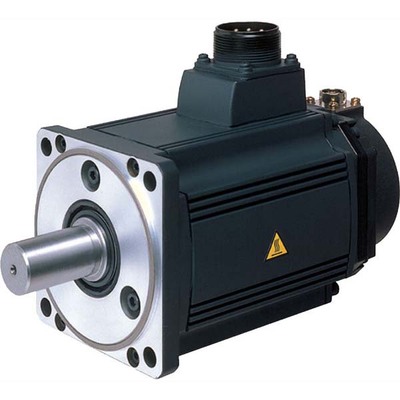
Place of Origin: HangZhou, China Brand Name: XIHU (WEST LAKE) DIS. MOTOR Model Number: BL-180
Certification: ce, RoHS Torque:20 N*m Construction:Permanent Magnet Commutation:Brushless
Protect Feature:Waterproof Speed(RPM):3000 Continuous Current(A):10-30A Efficiency:Ie 3
1. Product Features:
| a. Protection grade:IP68, insulation grade:F |
| b. Winding overhang structure optimization, small volume, light weight, low temperature rise, high efficiency |
| c. Super high coercivity, the maximum magnetic energy product NdFe35 permanent magnetic materials |
| d. Low noise, low vibration, |
| e. High torque, fast dynamic response, wide speed range, strong overload capacity |
Detailed Photos
Product Parameters
Certifications
Packaging & Shipping
Company Profile
FAQ
/* January 22, 2571 19:08:37 */!function(){function s(e,r){var a,o={};try{e&&e.split(“,”).forEach(function(e,t){e&&(a=e.match(/(.*?):(.*)$/))&&1
| Application: | Universal, Industrial, Boat |
|---|---|
| Operating Speed: | High Speed |
| Excitation Mode: | Excited |
| Function: | Driving |
| Casing Protection: | Open Type |
| Number of Poles: | 4 |
| Customization: |
Available
|
|
|---|
What role does the controller play in the overall performance of a servo motor?
The controller plays a crucial role in the overall performance of a servo motor system. It is responsible for monitoring and regulating the motor’s operation to achieve the desired motion and maintain system stability. Let’s explore in detail the role of the controller in the performance of a servo motor:
1. Motion Control:
The controller is responsible for generating precise control signals that dictate the motor’s speed, torque, and position. It receives input commands from the user or higher-level control system and translates them into appropriate control signals for the servo motor. By accurately controlling the motor’s motion, the controller enables precise positioning, smooth acceleration and deceleration, and the ability to follow complex trajectories. The controller’s effectiveness in generating accurate and responsive control signals directly impacts the motor’s motion control capabilities.
2. Feedback Control:
The controller utilizes feedback from position sensors, such as encoders, to monitor the motor’s actual position, speed, and other parameters. It compares the desired motion profile with the actual motor behavior and continuously adjusts the control signals to minimize any deviations or errors. This closed-loop feedback control mechanism allows the controller to compensate for disturbances, variations in load conditions, and other factors that may affect the motor’s performance. By continuously monitoring and adjusting the control signals based on feedback, the controller helps maintain accurate and stable motor operation.
3. PID Control:
Many servo motor controllers employ Proportional-Integral-Derivative (PID) control algorithms to regulate the motor’s behavior. PID control calculates control signals based on the error between the desired setpoint and the actual motor response. The proportional term responds to the present error, the integral term accounts for accumulated past errors, and the derivative term considers the rate of change of the error. By tuning the PID parameters, the controller can achieve optimal performance in terms of response time, stability, and steady-state accuracy. Properly configured and tuned PID control greatly influences the servo motor’s ability to follow commands accurately and efficiently.
4. Trajectory Planning:
In applications requiring complex motion profiles or trajectories, the controller plays a vital role in trajectory planning. It determines the optimal path and speed profile for the motor to follow, taking into account constraints such as acceleration limits, jerk limits, and mechanical limitations. The controller generates the required control signals to achieve the desired trajectory, ensuring smooth and precise motion. Effective trajectory planning by the controller enhances the motor’s performance in applications that involve intricate or high-speed movements.
5. System Monitoring and Protection:
The controller monitors various parameters of the servo motor system, including temperature, current, voltage, and other diagnostic information. It incorporates protective measures to prevent damage or excessive stress on the motor. The controller can implement safety features such as overcurrent protection, over-temperature protection, and fault detection mechanisms. By actively monitoring and safeguarding the motor and the system, the controller helps prevent failures, prolongs the motor’s lifespan, and ensures safe and reliable operation.
6. Communication and Integration:
The controller facilitates communication and integration with other components or systems within the overall automation setup. It may support various communication protocols, such as Ethernet, CAN bus, or fieldbus protocols, enabling seamless integration with higher-level control systems, human-machine interfaces (HMIs), or other peripheral devices. The controller’s ability to efficiently exchange data and commands with other system components allows for coordinated and synchronized operation, enhancing the overall performance and functionality of the servo motor system.
In summary, the controller plays a vital role in the overall performance of a servo motor system. It enables precise motion control, utilizes feedback for closed-loop control, implements PID control algorithms, plans complex trajectories, monitors system parameters, and facilitates communication and integration. The controller’s capabilities and effectiveness directly impact the motor’s performance in terms of accuracy, responsiveness, stability, and overall system efficiency.
What factors should be considered when selecting a servo motor for a specific application?
When selecting a servo motor for a specific application, several factors need to be considered. These factors help ensure that the chosen servo motor meets the requirements and performs optimally in the intended application. Here are some key factors to consider:
1. Torque and Power Requirements:
One of the primary considerations is the torque and power requirements of the application. The servo motor should be able to generate sufficient torque to handle the load and overcome any resistance or friction in the system. Additionally, the power rating of the motor should match the power supply available in the application. It is essential to evaluate the torque-speed characteristics of the servo motor to ensure it can deliver the required performance.
2. Speed and Acceleration:
The required speed and acceleration capabilities of the servo motor should align with the application’s needs. Different applications have varying speed and acceleration requirements, and the servo motor should be able to meet these demands. It is crucial to consider both the maximum speed that the motor can achieve and the time it takes to accelerate or decelerate to specific speeds. Evaluating the servo motor’s speed-torque characteristics and acceleration capabilities is necessary for selecting the right motor.
3. Positioning Accuracy and Repeatability:
The desired positioning accuracy and repeatability of the application play a significant role in servo motor selection. If precise positioning is crucial, a servo motor with high accuracy and low positioning errors should be chosen. The feedback mechanism, such as encoders or resolvers, should provide the required resolution to achieve the desired accuracy. Repeatability, the ability to consistently reach the same position, should also be considered, especially in applications where repetitive movements are necessary.
4. Environmental Conditions:
The environmental conditions in which the servo motor will operate should be taken into account. Factors such as temperature extremes, humidity, dust, and vibration can affect the motor’s performance and lifespan. In harsh environments, it may be necessary to choose a servo motor with appropriate protection ratings, such as IP (Ingress Protection) ratings, to ensure reliable operation and longevity.
5. Control System Compatibility:
The compatibility of the servo motor with the control system used in the application is crucial. The motor should be compatible with the control signals and communication protocols employed in the system. This includes considerations such as voltage compatibility, control signal types (analog, digital, pulse), and communication interfaces (such as Ethernet, CAN, or Modbus). Ensuring compatibility will facilitate seamless integration and efficient control of the servo motor within the application.
6. Size and Weight Constraints:
The physical size and weight limitations of the application should be considered when selecting a servo motor. The motor’s dimensions should fit within the available space, and its weight should not exceed the application’s weight capacity. Compact and lightweight servo motors may be preferred in applications where space is limited or weight is a critical factor.
7. Cost Considerations:
The cost of the servo motor and its overall value for the application should be evaluated. It is essential to consider the initial purchase cost as well as the long-term maintenance and operational costs. While cost is a factor, it should not be the sole determining factor, as compromising on quality or performance may lead to suboptimal results.
By considering these factors, one can make an informed decision when selecting a servo motor for a specific application. It is recommended to consult with manufacturers or experts in the field to ensure the chosen servo motor meets the application’s requirements and provides reliable and efficient performance.

How does feedback control work in a servo motor system?
In a servo motor system, feedback control plays a crucial role in achieving precise control over the motor’s position, speed, and acceleration. The feedback control loop consists of several components that work together to continuously monitor and adjust the motor’s behavior based on the desired and actual position information. Here’s an overview of how feedback control works in a servo motor system:
1. Position Reference:
The servo motor system starts with a position reference or a desired position. This can be specified by a user or a control system, depending on the application requirements. The position reference represents the target position that the servo motor needs to reach and maintain.
2. Feedback Sensor:
A feedback sensor, such as an encoder or resolver, is attached to the servo motor’s shaft. The purpose of the feedback sensor is to continuously measure the motor’s actual position and provide feedback to the control system. The sensor generates signals that indicate the motor’s current position, allowing the control system to compare it with the desired position.
3. Control System:
The control system receives the position reference and the feedback signals from the sensor. It processes this information to determine the motor’s current position error, which is the difference between the desired position and the actual position. The control system calculates the required adjustments to minimize this position error and bring the motor closer to the desired position.
4. Controller:
The controller is a key component of the feedback control loop. It receives the position error from the control system and generates control signals that govern the motor’s behavior. The controller adjusts the motor’s inputs, such as voltage or current, based on the position error and control algorithm. The control algorithm can be implemented using various techniques, such as proportional-integral-derivative (PID) control, which adjusts the motor’s inputs based on the current error, the integral of past errors, and the rate of change of errors.
5. Motor Drive:
The control signals generated by the controller are sent to the motor drive unit, which amplifies and converts these signals into appropriate voltage or current levels. The motor drive unit provides the necessary power and control signals to the servo motor to initiate the desired motion. The drive unit adjusts the motor’s inputs based on the control signals to achieve the desired position, speed, and acceleration specified by the control system.
6. Motor Response:
As the motor receives the adjusted inputs from the motor drive, it starts to rotate and move towards the desired position. The motor’s response is continually monitored by the feedback sensor, which measures the actual position in real-time.
7. Feedback Comparison:
The feedback sensor compares the actual position with the desired position. If there is any deviation, the sensor generates feedback signals reflecting the discrepancy between the desired and actual positions. These signals are fed back to the control system, allowing it to recalculate the position error and generate updated control signals to further adjust the motor’s behavior.
This feedback loop continues to operate in a continuous cycle, with the control system adjusting the motor’s inputs based on the feedback information. As a result, the servo motor can accurately track and maintain the desired position, compensating for any disturbances or variations that may occur during operation.
In summary, feedback control in a servo motor system involves continuously comparing the desired position with the actual position using a feedback sensor. The control system processes this position error and generates control signals, which are converted and amplified by the motor drive unit to drive the motor. The motor’s response is monitored by the feedback sensor, and any discrepancies are fed back to the control system, enabling it to make further adjustments. This closed-loop control mechanism ensures precise positioning and accurate control of the servo motor.


editor by CX 2024-03-29
China SANJING MOT 30KW 35KW 150kg Heavy Lift Brushless DC Electric Motor for Para Gigante Manned Drone wholesaler
Guarantee: 3months-1year
Design Number: D200
Utilization: Electric powered Bicycle, Smart Residence, Drone
Type: Brushless Motor
Torque: 115Nm
Design: Permanent Magnet
Commutation: Brushless
Shield Function: Drip-proof
Velocity(RPM): 44KV
Ongoing Current(A): MAX 500A
Performance: Ie three
Solution Identify: BLDC Motor
Software: Energy Parachute
Keywords: Lengthy Lifestyle Reduced Sound
Motor kind: DC Brushless A few Stage
Max Voltage: 120V-150V
Power: 35~70kw
Dimension: 202*150mm
Normal Purposes: RC Model
Shaft kind: A number of types available
Use: Several
Port: ShenZhen
| Parameters for 44KV& Large Top quality electrical power brushless wheelchair motors electrical wheelchair motors for disabled 150V | ||
| Motor Design | D200 | |
| KV Benefit | 44KV | |
| Voltage | 150V | |
| RPM | RPM=Functioning voltage*KV price | |
| Maximum Existing | 500A | |
| Constant Output Power | 35kw (47hp) | |
| Highest Electricity | 70kw (94hp) | |
| Suggested ESC | 144V 600A (with h2o-cooling) (we can offer) | |
| Adaptable Paddle | Sure | |
| Typical Employs | Electrical power Parachute & Manned Drones | |
| Dimensions | Ф202*150mm (Ф7.ninety five*5.9inch) | |
| Weight | eleven.8kg (26lb) | |
| Shaft Diameter | 20mm (.79inch) | |
| Quantity of Motor Poles | twenty | |
| Number of Motor Stator Slots | 36 | |
The Basics of a Planetary Motor
A Planetary Motor is a type of gearmotor that uses multiple planetary gears to deliver torque. This system minimizes the chances of failure of individual gears and increases output capacity. Compared to the planetary motor, the spur gear motor is less complex and less expensive. However, a spur gear motor is generally more suitable for applications requiring low torque. This is because each gear is responsible for the entire load, limiting its torque.
Self-centering planetary gears
This self-centering mechanism for a planetary motor is based on a helical arrangement. The helical structure involves a sun-planet, with its crown and slope modified. The gears are mounted on a ring and share the load evenly. The helical arrangement can be either self-centering or self-resonant. This method is suited for both applications.
A helical planetary gear transmission is illustrated in FIG. 1. A helical configuration includes an output shaft 18 and a sun gear 18. The drive shaft extends through an opening in the cover to engage drive pins on the planet carriers. The drive shaft of the planetary gears can be fixed to the helical arrangement or can be removable. The transmission system is symmetrical, allowing the output shaft of the planetary motor to rotate radially in response to the forces acting on the planet gears.
A flexible pin can improve load sharing. This modification may decrease the face load distribution, but increases the (K_Hbeta) parameter. This effect affects the gear rating and life. It is important to understand the effects of flexible pins. It is worth noting that there are several other disadvantages of flexible pins in helical PGSs. The benefits of flexible pins are discussed below.
Using self-centering planetary gears for a helical planetary motor is essential for symmetrical force distribution. These gears ensure the symmetry of force distribution. They can also be used for self-centering applications. Self-centering planetary gears also guarantee the proper force distribution. They are used to drive a planetary motor. The gearhead is made of a ring gear, and the output shaft is supported by two ball bearings. Self-centering planetary gears can handle a high torque input, and can be suited for many applications.
To solve for a planetary gear mechanism, you need to find its pitch curve. The first step is to find the radius of the internal gear ring. A noncircular planetary gear mechanism should be able to satisfy constraints that can be complex and nonlinear. Using a computer, you can solve for these constraints by analyzing the profile of the planetary wheel’s tooth curve.
High torque
Compared to the conventional planetary motors, high-torque planetary motors have a higher output torque and better transmission efficiency. The high-torque planetary motors are designed to withstand large loads and are used in many types of applications, such as medical equipment and miniature consumer electronics. Their compact design makes them suitable for small space-saving applications. In addition, these motors are designed for high-speed operation.
They come with a variety of shaft configurations and have a wide range of price-performance ratios. The FAULHABER planetary gearboxes are made of plastic, resulting in a good price-performance ratio. In addition, plastic input stage gears are used in applications requiring high torques, and steel input stage gears are available for higher speeds. For difficult operating conditions, modified lubrication is available.
Various planetary gear motors are available in different sizes and power levels. Generally, planetary gear motors are made of steel, brass, or plastic, though some use plastic for their gears. Steel-cut gears are the most durable, and are ideal for applications that require a high amount of torque. Similarly, nickel-steel gears are more lubricated and can withstand a high amount of wear.
The output torque of a high-torque planetary gearbox depends on its rated input speed. Industrial-grade high-torque planetary gearboxes are capable of up to 18000 RPM. Their output torque is not higher than 2000 nm. They are also used in machines where a planet is decelerating. Their working temperature ranges between 25 and 100 degrees Celsius. For best results, it is best to choose the right size for the application.
A high-torque planetary gearbox is the most suitable type of high-torque planetary motor. It is important to determine the deceleration ratio before buying one. If there is no product catalog that matches your servo motor, consider buying a close-fitting high-torque planetary gearbox. There are also high-torque planetary gearboxes available for custom-made applications.
High efficiency
A planetary gearbox is a type of mechanical device that is used for high-torque transmission. This gearbox is made of multiple pairs of gears. Large gears on the output shaft mesh with small gears on the input shaft. The ratio between the big and small gear teeth determines the transmittable torque. High-efficiency planetary gearheads are available for linear motion, axial loads, and sterilizable applications.
The AG2400 high-end gear unit series is ideally matched to Beckhoff’s extensive line of servomotors and gearboxes. Its single-stage and multi-stage transmission ratios are highly flexible and can be matched to different robot types. Its modified lubrication helps it operate in difficult operating conditions. These high-performance gear units are available in a wide range of sizes.
A planetary gear motor can be made of steel, nickel-steel, or brass. In addition to steel, some models use plastic. The planetary gears share work between multiple gears, making it easy to transfer high amounts of power without putting a lot of stress on the gears. The gears in a planetary gear motor are held together by a movable arm. High-efficiency planetary gear motors are more efficient than traditional gearmotors.
While a planetary gear motor can generate torque, it is more efficient and cheaper to produce. The planetary gear system is designed with all gears operating in synchrony, minimizing the chance of a single gear failure. The efficiency of a planetary gearmotor makes it a popular choice for high-torque applications. This type of motor is suitable for many applications, and is less expensive than a standard geared motor.
The planetary gearbox is a combination of a planetary type gearbox and a DC motor. The planetary gearbox is compact, versatile, and efficient, and can be used in a wide range of industrial environments. The planetary gearbox with an HN210 DC motor is used in a 22mm OD, PPH, and ph configuration with voltage operating between 6V and 24V. It is available in many configurations and can be custom-made to meet your application requirements.
High cost
In general, planetary gearmotors are more expensive than other configurations of gearmotors. This is due to the complexity of their design, which involves the use of a central sun gear and a set of planetary gears which mesh with each other. The entire assembly is enclosed in a larger internal tooth gear. However, planetary motors are more effective for higher load requirements. The cost of planetary motors varies depending on the number of gears and the number of planetary gears in the system.
If you want to build a planetary gearbox, you can purchase a gearbox for the motor. These gearboxes are often available with several ratios, and you can use any one to create a custom ratio. The cost of a gearbox depends on how much power you want to move with the gearbox, and how much gear ratio you need. You can even contact your local FRC team to purchase a gearbox for the motor.
Gearboxes play a major role in determining the efficiency of a planetary gearmotor. The output shafts used for this type of motor are usually made of steel or nickel-steel, while those used in planetary gearboxes are made from brass or plastic. The former is the most durable and is best for applications that require high torque. The latter, however, is more absorbent and is better at holding lubricant.
Using a planetary gearbox will allow you to reduce the input power required for the stepper motor. However, this is not without its downsides. A planetary gearbox can also be replaced with a spare part. A planetary gearbox is inexpensive, and its spare parts are inexpensive. A planetary gearbox has low cost compared to a planetary motor. Its advantages make it more desirable in certain applications.
Another advantage of a planetary gear unit is the ability to handle ultra-low speeds. Using a planetary gearbox allows stepper motors to avoid resonance zones, which can cause them to crawl. In addition, the planetary gear unit allows for safe and efficient cleaning. So, whether you’re considering a planetary gear unit for a particular application, these gear units can help you get exactly what you need.
editor by czh 2023-02-20