Product Description
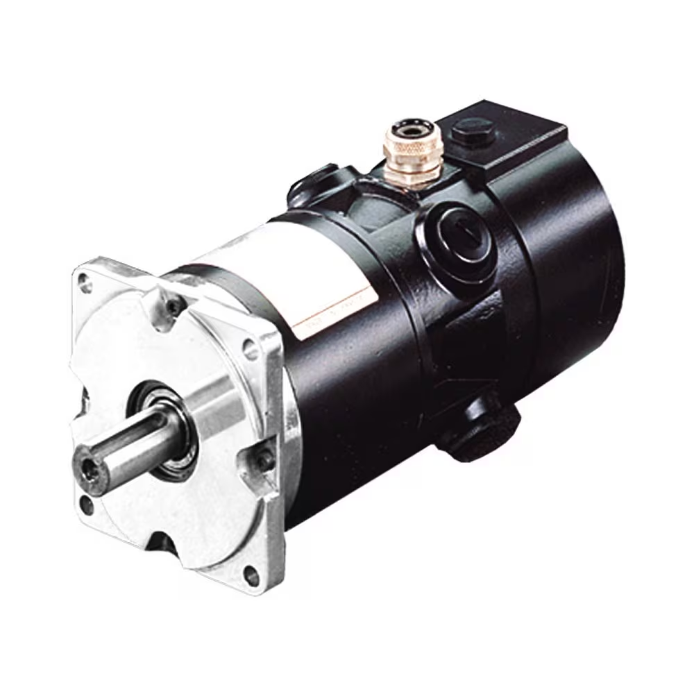
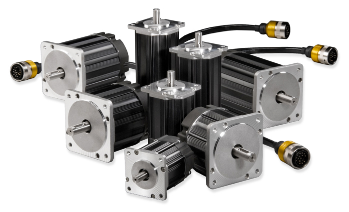
2.6KW AC Servos motor 2.6KW 2500RPM 10N.M. Single-Phase cnc servos drive and servo motor for industrial sewing machine
|
Input power |
Control power |
Single phase 220VAC |
|
Main power |
Single-phase/three-phase 220VAC |
|
|
Working |
Temperature |
0 ~ 45°C |
|
Humidity |
≤90% RH or less, no condensation |
|
|
Altitude |
Altitude ≤1000m |
|
|
Installatioon Environment |
No corrosive gas, flammable gas, oil mist or dust, etc |
|
|
Installation method |
Vertical installation |
|
|
Encoder feedback |
2500 p/r (resolution: 10000), incremental encoder |
|
|
Control signal |
Digital input |
10 ordinary digital inputs, with configurable functions. |
|
Digital output |
6 digital outputs, with configurable functions. |
|
|
Pulse signal |
Input |
2 high-speed inputs: differential (600K) and single-ended (200K) pulses. Support pulse input mode: PULS+DIR, A+B, CW+CCW |
|
Output |
3 high-speed pulse outputs, output signal form: 5V differential signal. 1 channel Z signal single-ended output signal. |
|
|
Analog signal |
Input |
2 analog inputs, 12-bit resolution, input range -10~+10V. AI2 is fixed as the torque limit input |
|
Output |
None |
|
|
Communication function |
RS485 communication, Modbus protocol. The main controller can control the position/speed/torque of the servo through RS485, up to |
|
|
Display panel and key operation |
5 butions (Mode, Set, Left, Up, Down) and 6 digital tubes |
|
|
Regenerative discharge braking resistor |
Built-in 100W, 40Ω braking resistor. In frequent braking situations, an external braking resistor is required |
|
Applications
/* January 22, 2571 19:08:37 */!function(){function s(e,r){var a,o={};try{e&&e.split(“,”).forEach(function(e,t){e&&(a=e.match(/(.*?):(.*)$/))&&1
| Application: | Industrial |
|---|---|
| Operating Speed: | High Speed |
| Excitation Mode: | Permanent Magnet Excitation |
| Function: | Driving |
| Casing Protection: | Protection Type |
| Number of Poles: | 2 |
| Samples: |
US$ 120/Piece
1 Piece(Min.Order) | |
|---|
| Customization: |
Available
|
|
|---|
Are there advancements or trends in servo motor technology that users should be aware of?
Yes, there have been significant advancements and emerging trends in servo motor technology that users should be aware of. These developments aim to enhance performance, improve efficiency, and provide new capabilities. Here are some noteworthy advancements and trends in servo motor technology:
1. Higher Power Density:
Advancements in servo motor design and manufacturing techniques have led to higher power densities. This means that modern servo motors can deliver more power in a smaller and lighter package. Higher power density allows for more compact and efficient machine designs, particularly in applications with limited space or weight restrictions.
2. Improved Efficiency:
Efficiency is a crucial aspect of servo motor technology. Manufacturers are continuously striving to improve motor efficiency to minimize energy consumption and reduce operating costs. Advanced motor designs, optimized winding configurations, and the use of high-quality materials contribute to higher efficiency levels, resulting in energy savings and lower heat generation.
3. Integration of Electronics and Control:
Integration of electronics and control functions directly into servo motors is becoming increasingly common. This trend eliminates the need for external motor controllers or drives, simplifies wiring and installation, and reduces overall system complexity. Integrated servo motors often include features such as on-board motion control, communication interfaces, and safety features.
4. Digitalization and Connectivity:
Servo motor technology is embracing digitalization and connectivity trends. Many modern servo motors come equipped with digital interfaces, such as Ethernet or fieldbus protocols, enabling seamless integration with industrial communication networks. This connectivity allows for real-time monitoring, diagnostics, and remote control of servo motors, facilitating condition monitoring, predictive maintenance, and system optimization.
5. Advanced Feedback Systems:
Feedback systems play a critical role in servo motor performance. Recent advancements in feedback technology have resulted in more accurate and higher-resolution encoders, resolvers, and sensors. These advanced feedback systems provide precise position and velocity information, enabling improved motion control, better accuracy, and enhanced dynamic response in servo motor applications.
6. Smart and Adaptive Control Algorithms:
Servo motor control algorithms have evolved to include smart and adaptive features. These algorithms can adapt to changing load conditions, compensate for disturbances, and optimize motor performance based on real-time feedback. Smart control algorithms contribute to smoother operation, increased stability, and improved tracking accuracy in various applications.
7. Safety and Functional Safety:
Safety is a paramount concern in industrial automation. Servo motor technology has incorporated safety features and functional safety standards to ensure the protection of personnel and equipment. Safety-rated servo motors often include features such as safe torque off (STO) functionality, safe motion control, and compliance with safety standards like ISO 13849 and IEC 61508.
It’s important for users to stay informed about these advancements and trends in servo motor technology. By understanding the latest developments, users can make informed decisions when selecting and implementing servo motors, leading to improved performance, efficiency, and reliability in their applications.
How is the size of a servo motor determined based on application requirements?
The size of a servo motor is an important consideration when selecting a motor for a specific application. The size of the motor is determined based on various factors related to the application requirements. Let’s explore how the size of a servo motor is determined:
1. Torque Requirements:
One of the primary factors in determining the size of a servo motor is the torque requirements of the application. The motor should be able to generate sufficient torque to handle the load and overcome any resistance or friction in the system. The required torque depends on factors such as the weight of the load, the distance from the motor’s axis of rotation, and any additional forces acting on the system. By analyzing the torque requirements, one can select a servo motor with an appropriate size and torque rating to meet the application’s needs.
2. Speed and Acceleration Requirements:
The desired speed and acceleration capabilities of the application also influence the size of the servo motor. Different applications have varying speed and acceleration requirements, and the motor needs to be capable of achieving the desired performance. Higher speeds and accelerations may require larger motors with more powerful components to handle the increased forces and stresses. By considering the required speed and acceleration, one can determine the size of the motor that can meet these demands.
3. Inertia and Load Inertia Ratio:
The inertia of the load and the inertia ratio between the load and the servo motor are important considerations in sizing the motor. Inertia refers to the resistance of an object to changes in its rotational motion. If the load has a high inertia, it requires a servo motor with sufficient size and torque to accelerate and decelerate the load effectively. The inertia ratio, which is the ratio of the load inertia to the motor inertia, affects the motor’s ability to control the load’s motion accurately. A proper balance between the load and motor inertia is necessary to achieve optimal performance and stability in the system.
4. Duty Cycle and Continuous Operation:
The duty cycle and continuous operation requirements of the application also impact the motor size selection. Duty cycle refers to the ratio of the motor’s operating time to the total cycle time. Applications with high-duty cycles or continuous operation may require larger motors that can handle sustained operation without overheating or performance degradation. It is important to consider the motor’s continuous torque rating and thermal characteristics to ensure it can operate reliably under the given duty cycle requirements.
5. Physical Space Constraints:
The physical space available for installing the servo motor is another factor to consider. The motor’s dimensions should fit within the available space, considering factors such as motor length, diameter, and any mounting requirements. It is essential to ensure that the chosen motor can be easily integrated into the system without interfering with other components or causing space constraints.
6. Weight Limitations:
The weight limitations of the application may influence the motor size selection. If there are weight restrictions, such as in mobile or lightweight applications, it is necessary to choose a servo motor that is compact and lightweight while still providing the required performance. Lighter servo motors can help optimize the overall weight and balance of the system.
7. Cost Considerations:
Cost is also a factor to consider when determining the size of a servo motor. Larger motors with higher torque and performance capabilities tend to be more expensive. It is important to strike a balance between the required performance and the cost constraints of the application. Analyzing the cost-effectiveness and overall value of the motor in relation to the application requirements is essential.
By considering these factors, one can determine the appropriate size of a servo motor that can meet the specific application requirements. It is advisable to consult with manufacturers or experts in the field to ensure the chosen motor size aligns with the application needs and provides optimal performance and reliability.
Can you explain the difference between a servo motor and a regular electric motor?
A servo motor and a regular electric motor are both types of electric motors, but they have distinct differences in terms of design, control, and functionality.
A regular electric motor, also known as an induction motor or a DC motor, is designed to convert electrical energy into mechanical energy. It consists of a rotor, which rotates, and a stator, which surrounds the rotor and generates a rotating magnetic field. The rotor is connected to an output shaft, and when current flows through the motor’s windings, it creates a magnetic field that interacts with the stator’s magnetic field, resulting in rotational motion.
On the other hand, a servo motor is a more specialized type of electric motor that incorporates additional components for precise control of position, speed, and acceleration. It consists of a regular electric motor, a sensor or encoder, and a feedback control system. The sensor or encoder provides feedback on the motor’s current position, and this information is used by the control system to adjust the motor’s behavior.
The key difference between a servo motor and a regular electric motor lies in their control mechanisms. A regular electric motor typically operates at a fixed speed based on the voltage and frequency of the power supply. In contrast, a servo motor can be controlled to rotate to a specific angle or position and maintain that position accurately. The control system continuously monitors the motor’s actual position through the feedback sensor and adjusts the motor’s operation to achieve the desired position or follow a specific trajectory.
Another distinction is the torque output of the motors. Regular electric motors generally provide high torque at low speeds and lower torque at higher speeds. In contrast, servo motors are designed to deliver high torque at both low and high speeds, which makes them suitable for applications that require precise and dynamic motion control.
Furthermore, servo motors often have a more compact and lightweight design compared to regular electric motors. They are commonly used in applications where precise positioning, speed control, and responsiveness are critical, such as robotics, CNC machines, automation systems, and remote-controlled vehicles.
In summary, while both servo motors and regular electric motors are used to convert electrical energy into mechanical energy, servo motors offer enhanced control capabilities, precise positioning, and high torque at various speeds, making them well-suited for applications that require accurate and dynamic motion control.


editor by CX 2024-04-10
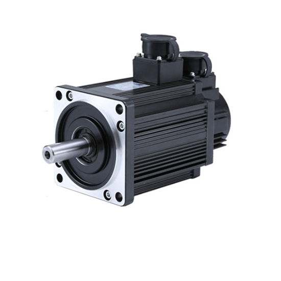
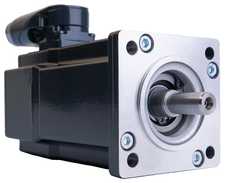
China Good quality 2kw Single Phase AC Electric Brushless DC Motor BLDC Lift Servo Motor vacuum pump ac
Product Description
Product Description
Quick Details
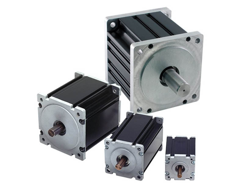
Place of Origin: HangZhou, China Brand Name: XIHU (WEST LAKE) DIS. MOTOR Model Number: BL-180
Certification: ce, RoHS Torque:20 N*m Construction:Permanent Magnet Commutation:Brushless
Protect Feature:Waterproof Speed(RPM):3000 Continuous Current(A):10-30A Efficiency:Ie 3
1. Product Features:
| a. Protection grade:IP68, insulation grade:F |
| b. Winding overhang structure optimization, small volume, light weight, low temperature rise, high efficiency |
| c. Super high coercivity, the maximum magnetic energy product NdFe35 permanent magnetic materials |
| d. Low noise, low vibration, |
| e. High torque, fast dynamic response, wide speed range, strong overload capacity |
Detailed Photos
Product Parameters
Certifications
Packaging & Shipping
Company Profile
FAQ
/* January 22, 2571 19:08:37 */!function(){function s(e,r){var a,o={};try{e&&e.split(“,”).forEach(function(e,t){e&&(a=e.match(/(.*?):(.*)$/))&&1
| Application: | Universal, Industrial, Boat |
|---|---|
| Operating Speed: | High Speed |
| Excitation Mode: | Excited |
| Function: | Driving |
| Casing Protection: | Open Type |
| Number of Poles: | 4 |
| Customization: |
Available
|
|
|---|
What role does the controller play in the overall performance of a servo motor?
The controller plays a crucial role in the overall performance of a servo motor system. It is responsible for monitoring and regulating the motor’s operation to achieve the desired motion and maintain system stability. Let’s explore in detail the role of the controller in the performance of a servo motor:
1. Motion Control:
The controller is responsible for generating precise control signals that dictate the motor’s speed, torque, and position. It receives input commands from the user or higher-level control system and translates them into appropriate control signals for the servo motor. By accurately controlling the motor’s motion, the controller enables precise positioning, smooth acceleration and deceleration, and the ability to follow complex trajectories. The controller’s effectiveness in generating accurate and responsive control signals directly impacts the motor’s motion control capabilities.
2. Feedback Control:
The controller utilizes feedback from position sensors, such as encoders, to monitor the motor’s actual position, speed, and other parameters. It compares the desired motion profile with the actual motor behavior and continuously adjusts the control signals to minimize any deviations or errors. This closed-loop feedback control mechanism allows the controller to compensate for disturbances, variations in load conditions, and other factors that may affect the motor’s performance. By continuously monitoring and adjusting the control signals based on feedback, the controller helps maintain accurate and stable motor operation.
3. PID Control:
Many servo motor controllers employ Proportional-Integral-Derivative (PID) control algorithms to regulate the motor’s behavior. PID control calculates control signals based on the error between the desired setpoint and the actual motor response. The proportional term responds to the present error, the integral term accounts for accumulated past errors, and the derivative term considers the rate of change of the error. By tuning the PID parameters, the controller can achieve optimal performance in terms of response time, stability, and steady-state accuracy. Properly configured and tuned PID control greatly influences the servo motor’s ability to follow commands accurately and efficiently.
4. Trajectory Planning:
In applications requiring complex motion profiles or trajectories, the controller plays a vital role in trajectory planning. It determines the optimal path and speed profile for the motor to follow, taking into account constraints such as acceleration limits, jerk limits, and mechanical limitations. The controller generates the required control signals to achieve the desired trajectory, ensuring smooth and precise motion. Effective trajectory planning by the controller enhances the motor’s performance in applications that involve intricate or high-speed movements.
5. System Monitoring and Protection:
The controller monitors various parameters of the servo motor system, including temperature, current, voltage, and other diagnostic information. It incorporates protective measures to prevent damage or excessive stress on the motor. The controller can implement safety features such as overcurrent protection, over-temperature protection, and fault detection mechanisms. By actively monitoring and safeguarding the motor and the system, the controller helps prevent failures, prolongs the motor’s lifespan, and ensures safe and reliable operation.
6. Communication and Integration:
The controller facilitates communication and integration with other components or systems within the overall automation setup. It may support various communication protocols, such as Ethernet, CAN bus, or fieldbus protocols, enabling seamless integration with higher-level control systems, human-machine interfaces (HMIs), or other peripheral devices. The controller’s ability to efficiently exchange data and commands with other system components allows for coordinated and synchronized operation, enhancing the overall performance and functionality of the servo motor system.
In summary, the controller plays a vital role in the overall performance of a servo motor system. It enables precise motion control, utilizes feedback for closed-loop control, implements PID control algorithms, plans complex trajectories, monitors system parameters, and facilitates communication and integration. The controller’s capabilities and effectiveness directly impact the motor’s performance in terms of accuracy, responsiveness, stability, and overall system efficiency.
What factors should be considered when selecting a servo motor for a specific application?
When selecting a servo motor for a specific application, several factors need to be considered. These factors help ensure that the chosen servo motor meets the requirements and performs optimally in the intended application. Here are some key factors to consider:
1. Torque and Power Requirements:
One of the primary considerations is the torque and power requirements of the application. The servo motor should be able to generate sufficient torque to handle the load and overcome any resistance or friction in the system. Additionally, the power rating of the motor should match the power supply available in the application. It is essential to evaluate the torque-speed characteristics of the servo motor to ensure it can deliver the required performance.
2. Speed and Acceleration:
The required speed and acceleration capabilities of the servo motor should align with the application’s needs. Different applications have varying speed and acceleration requirements, and the servo motor should be able to meet these demands. It is crucial to consider both the maximum speed that the motor can achieve and the time it takes to accelerate or decelerate to specific speeds. Evaluating the servo motor’s speed-torque characteristics and acceleration capabilities is necessary for selecting the right motor.
3. Positioning Accuracy and Repeatability:
The desired positioning accuracy and repeatability of the application play a significant role in servo motor selection. If precise positioning is crucial, a servo motor with high accuracy and low positioning errors should be chosen. The feedback mechanism, such as encoders or resolvers, should provide the required resolution to achieve the desired accuracy. Repeatability, the ability to consistently reach the same position, should also be considered, especially in applications where repetitive movements are necessary.
4. Environmental Conditions:
The environmental conditions in which the servo motor will operate should be taken into account. Factors such as temperature extremes, humidity, dust, and vibration can affect the motor’s performance and lifespan. In harsh environments, it may be necessary to choose a servo motor with appropriate protection ratings, such as IP (Ingress Protection) ratings, to ensure reliable operation and longevity.
5. Control System Compatibility:
The compatibility of the servo motor with the control system used in the application is crucial. The motor should be compatible with the control signals and communication protocols employed in the system. This includes considerations such as voltage compatibility, control signal types (analog, digital, pulse), and communication interfaces (such as Ethernet, CAN, or Modbus). Ensuring compatibility will facilitate seamless integration and efficient control of the servo motor within the application.
6. Size and Weight Constraints:
The physical size and weight limitations of the application should be considered when selecting a servo motor. The motor’s dimensions should fit within the available space, and its weight should not exceed the application’s weight capacity. Compact and lightweight servo motors may be preferred in applications where space is limited or weight is a critical factor.
7. Cost Considerations:
The cost of the servo motor and its overall value for the application should be evaluated. It is essential to consider the initial purchase cost as well as the long-term maintenance and operational costs. While cost is a factor, it should not be the sole determining factor, as compromising on quality or performance may lead to suboptimal results.
By considering these factors, one can make an informed decision when selecting a servo motor for a specific application. It is recommended to consult with manufacturers or experts in the field to ensure the chosen servo motor meets the application’s requirements and provides reliable and efficient performance.

How does feedback control work in a servo motor system?
In a servo motor system, feedback control plays a crucial role in achieving precise control over the motor’s position, speed, and acceleration. The feedback control loop consists of several components that work together to continuously monitor and adjust the motor’s behavior based on the desired and actual position information. Here’s an overview of how feedback control works in a servo motor system:
1. Position Reference:
The servo motor system starts with a position reference or a desired position. This can be specified by a user or a control system, depending on the application requirements. The position reference represents the target position that the servo motor needs to reach and maintain.
2. Feedback Sensor:
A feedback sensor, such as an encoder or resolver, is attached to the servo motor’s shaft. The purpose of the feedback sensor is to continuously measure the motor’s actual position and provide feedback to the control system. The sensor generates signals that indicate the motor’s current position, allowing the control system to compare it with the desired position.
3. Control System:
The control system receives the position reference and the feedback signals from the sensor. It processes this information to determine the motor’s current position error, which is the difference between the desired position and the actual position. The control system calculates the required adjustments to minimize this position error and bring the motor closer to the desired position.
4. Controller:
The controller is a key component of the feedback control loop. It receives the position error from the control system and generates control signals that govern the motor’s behavior. The controller adjusts the motor’s inputs, such as voltage or current, based on the position error and control algorithm. The control algorithm can be implemented using various techniques, such as proportional-integral-derivative (PID) control, which adjusts the motor’s inputs based on the current error, the integral of past errors, and the rate of change of errors.
5. Motor Drive:
The control signals generated by the controller are sent to the motor drive unit, which amplifies and converts these signals into appropriate voltage or current levels. The motor drive unit provides the necessary power and control signals to the servo motor to initiate the desired motion. The drive unit adjusts the motor’s inputs based on the control signals to achieve the desired position, speed, and acceleration specified by the control system.
6. Motor Response:
As the motor receives the adjusted inputs from the motor drive, it starts to rotate and move towards the desired position. The motor’s response is continually monitored by the feedback sensor, which measures the actual position in real-time.
7. Feedback Comparison:
The feedback sensor compares the actual position with the desired position. If there is any deviation, the sensor generates feedback signals reflecting the discrepancy between the desired and actual positions. These signals are fed back to the control system, allowing it to recalculate the position error and generate updated control signals to further adjust the motor’s behavior.
This feedback loop continues to operate in a continuous cycle, with the control system adjusting the motor’s inputs based on the feedback information. As a result, the servo motor can accurately track and maintain the desired position, compensating for any disturbances or variations that may occur during operation.
In summary, feedback control in a servo motor system involves continuously comparing the desired position with the actual position using a feedback sensor. The control system processes this position error and generates control signals, which are converted and amplified by the motor drive unit to drive the motor. The motor’s response is monitored by the feedback sensor, and any discrepancies are fed back to the control system, enabling it to make further adjustments. This closed-loop control mechanism ensures precise positioning and accurate control of the servo motor.
editor by CX 2024-03-29
China best Power Protection Single Phase Pcsvc-20000va Servo Motor LED Display manufacturer
Product Description
Advantages:
1.AC Automatic Voltage Stabilizer
2.LED Display:Display various protection data
3.Protection Function:Over Voltage Protect;Low Voltage Protect;Over Loading Protect;Over Temperture;Short Circuit Protect
4.Wide input voltage range
5.Efficiency more than 90%
6.No additional waveform distortion
Specifications:
1.Model:PCSVC-20000VA
2.Input Voltage:AC270-430V
3.Output Voltage:380v±3% adjustable
4.Frequency:50HZ/60HZ
5.Phase: Single Phase
6.Packing Size:50.5*50.5*106.0cm
7.G.W.:90kgs
Application:
1.Computer
2.Test equipment
3.Lighting equipment
4.Alarm and security system
5.X-ray equipment
6.Medical equipment
7.Duplicator
8.Boadcasting equipment
9.Numeric control machine tool
10.Industrial robot
11.Hi-Fi equipment
| Model | PCSVC-6000VA | PCSVC-10000VA | PCSVC-15000VA |
| PCSVC-20000VA | PCSVC-30000VA | PCSVC-45000VA |
| TECHNOLOGY | Servo Motor Control System+Micro computer ptogramed control | |||||||
|
LED DISPLAY
|
Info | Input Voltage/Output Voltage/Load Usage/Time Delay/Normal Working/Protection | ||||||
| Protection
|
Over voltage | Output Voltage≥243±4V | ||||||
| Low Voltage | Output Voltage≤188±4v | |||||||
| Over Loading | More than 120% | |||||||
| Over Temperture | 120ºC±10ºC | |||||||
| Delay Time | Long time(255 seconds)/Short time(5 seconds) | |||||||
| Circuit Breaker | Regulator/Bypass | |||||||
| Language | English/Russian/Chinese | |||||||
| INPUT VOLTAGE | AC270V-430V | |||||||
| OUTPUT VOLTAGE | 380V±3% adjustable | |||||||
| FREQUENCY | 50HZ/60HZ | |||||||
| PHASE | Single Phase | |||||||
| EFFICIENCY | ≥90% | |||||||
| AMBIENT TEMPERATURE | -15ºC-45ºC | |||||||
| RELATIVE HUMIDITY | <95% | |||||||
| WAVEFORM DISTORTION | No additional wave from distortion | |||||||
| INSULATING RESISTANCE | Normally more than 2MΩ | |||||||
| SPECIFICATIONS | ||||||||
| POWER | 6000VA | 10000VA | 15000VA | 20000VA | 30000VA | 45000VA | ||
| PACKING SIZE(CM) | 45.0*45.0*90.0 | 45.0*45.0*90.0 | 50.5*50.0*106.0 | 50.5*50.5*106.5 | 59.0*60.5*115.0 | 75.0*65.5*132.0 | ||
| PACKING(pcs) | 1 | 1 | 1 | 1 | 1 | 1 | ||
| G.M(kgs) | 55.00 | 65.00 | 80.00 | 90.00 | 115.00 | 185.00 | ||
/* March 10, 2571 17:59:20 */!function(){function s(e,r){var a,o={};try{e&&e.split(“,”).forEach(function(e,t){e&&(a=e.match(/(.*?):(.*)$/))&&1
| Current Type: | AC |
|---|---|
| Phase: | Single Phase |
| Frequency Characteristics: | Intermediate Frequency |
| Usage: | Triac |
| Frequency: | Intermediate Frequency |
| Size: | Medium |
| Customization: |
Available
|
|
|---|
What role does the controller play in the overall performance of a servo motor?
The controller plays a crucial role in the overall performance of a servo motor system. It is responsible for monitoring and regulating the motor’s operation to achieve the desired motion and maintain system stability. Let’s explore in detail the role of the controller in the performance of a servo motor:
1. Motion Control:
The controller is responsible for generating precise control signals that dictate the motor’s speed, torque, and position. It receives input commands from the user or higher-level control system and translates them into appropriate control signals for the servo motor. By accurately controlling the motor’s motion, the controller enables precise positioning, smooth acceleration and deceleration, and the ability to follow complex trajectories. The controller’s effectiveness in generating accurate and responsive control signals directly impacts the motor’s motion control capabilities.
2. Feedback Control:
The controller utilizes feedback from position sensors, such as encoders, to monitor the motor’s actual position, speed, and other parameters. It compares the desired motion profile with the actual motor behavior and continuously adjusts the control signals to minimize any deviations or errors. This closed-loop feedback control mechanism allows the controller to compensate for disturbances, variations in load conditions, and other factors that may affect the motor’s performance. By continuously monitoring and adjusting the control signals based on feedback, the controller helps maintain accurate and stable motor operation.
3. PID Control:
Many servo motor controllers employ Proportional-Integral-Derivative (PID) control algorithms to regulate the motor’s behavior. PID control calculates control signals based on the error between the desired setpoint and the actual motor response. The proportional term responds to the present error, the integral term accounts for accumulated past errors, and the derivative term considers the rate of change of the error. By tuning the PID parameters, the controller can achieve optimal performance in terms of response time, stability, and steady-state accuracy. Properly configured and tuned PID control greatly influences the servo motor’s ability to follow commands accurately and efficiently.
4. Trajectory Planning:
In applications requiring complex motion profiles or trajectories, the controller plays a vital role in trajectory planning. It determines the optimal path and speed profile for the motor to follow, taking into account constraints such as acceleration limits, jerk limits, and mechanical limitations. The controller generates the required control signals to achieve the desired trajectory, ensuring smooth and precise motion. Effective trajectory planning by the controller enhances the motor’s performance in applications that involve intricate or high-speed movements.
5. System Monitoring and Protection:
The controller monitors various parameters of the servo motor system, including temperature, current, voltage, and other diagnostic information. It incorporates protective measures to prevent damage or excessive stress on the motor. The controller can implement safety features such as overcurrent protection, over-temperature protection, and fault detection mechanisms. By actively monitoring and safeguarding the motor and the system, the controller helps prevent failures, prolongs the motor’s lifespan, and ensures safe and reliable operation.
6. Communication and Integration:
The controller facilitates communication and integration with other components or systems within the overall automation setup. It may support various communication protocols, such as Ethernet, CAN bus, or fieldbus protocols, enabling seamless integration with higher-level control systems, human-machine interfaces (HMIs), or other peripheral devices. The controller’s ability to efficiently exchange data and commands with other system components allows for coordinated and synchronized operation, enhancing the overall performance and functionality of the servo motor system.
In summary, the controller plays a vital role in the overall performance of a servo motor system. It enables precise motion control, utilizes feedback for closed-loop control, implements PID control algorithms, plans complex trajectories, monitors system parameters, and facilitates communication and integration. The controller’s capabilities and effectiveness directly impact the motor’s performance in terms of accuracy, responsiveness, stability, and overall system efficiency.
Can you explain the concept of torque and speed in relation to servo motors?
Torque and speed are two essential parameters in understanding the performance characteristics of servo motors. Let’s explore these concepts in relation to servo motors:
Torque:
Torque refers to the rotational force produced by a servo motor. It determines the motor’s ability to generate rotational motion and overcome resistance or load. Torque is typically measured in units of force multiplied by distance, such as Nm (Newton-meter) or oz-in (ounce-inch).
The torque output of a servo motor is crucial in applications where the motor needs to move or control a load. The motor must provide enough torque to overcome the resistance or friction in the system and maintain the desired position or motion. Higher torque allows the motor to handle heavier loads or more challenging operating conditions.
It is important to note that the torque characteristics of a servo motor may vary depending on the speed or position of the motor. Manufacturers often provide torque-speed curves or torque-position curves, which illustrate the motor’s torque capabilities at different operating points. Understanding these curves helps in selecting a servo motor that can deliver the required torque for a specific application.
Speed:
Speed refers to the rotational velocity at which a servo motor operates. It indicates how fast the motor can rotate and how quickly it can achieve the desired position or motion. Speed is typically measured in units of revolutions per minute (RPM) or radians per second (rad/s).
The speed of a servo motor is crucial in applications that require rapid movements or high-speed operations. It determines the motor’s responsiveness and the system’s overall performance. Different servo motors have different speed capabilities, and the maximum achievable speed is often specified by the manufacturer.
It is worth noting that the speed of a servo motor may also affect its torque output. Some servo motors exhibit a phenomenon known as “speed-torque curve,” where the motor’s torque decreases as the speed increases. This behavior is influenced by factors such as motor design, winding resistance, and control algorithms. Understanding the speed-torque characteristics of a servo motor is important for selecting a motor that can meet the speed requirements of the application while maintaining sufficient torque.
Overall, torque and speed are interrelated parameters that determine the performance capabilities of a servo motor. The torque capability determines the motor’s ability to handle loads, while the speed capability determines how quickly the motor can achieve the desired motion. When selecting a servo motor, it is essential to consider both the torque and speed requirements of the application to ensure that the motor can deliver the desired performance.
What is a servo motor, and how does it function in automation systems?
A servo motor is a type of motor specifically designed for precise control of angular or linear position, velocity, and acceleration. It is widely used in various automation systems where accurate motion control is required. Let’s explore the concept of servo motors and how they function in automation systems:
A servo motor consists of a motor, a position feedback device (such as an encoder or resolver), and a control system. The control system receives input signals, typically in the form of electrical pulses or analog signals, indicating the desired position or speed. Based on these signals and the feedback from the position sensor, the control system adjusts the motor’s operation to achieve the desired motion.
The functioning of a servo motor in an automation system involves the following steps:
- Signal Input: The automation system provides a control signal to the servo motor, indicating the desired position, speed, or other motion parameters. This signal can be generated by a human operator, a computer, a programmable logic controller (PLC), or other control devices.
- Feedback System: The servo motor incorporates a position feedback device, such as an encoder or resolver, which continuously monitors the motor’s actual position. This feedback information is sent back to the control system, allowing it to compare the actual position with the desired position specified by the input signal.
- Control System: The control system, typically housed within the servo motor or an external servo drive, receives the input signal and the feedback from the position sensor. It processes this information and generates the appropriate control signals to the motor.
- Motor Operation: Based on the control signals received from the control system, the servo motor adjusts its operation to achieve the desired motion. The control system varies the motor’s voltage, current, or frequency to control the motor’s speed, torque, or position accurately.
- Closed-Loop Control: Servo motors operate in a closed-loop control system. The feedback information from the position sensor allows the control system to continuously monitor and adjust the motor’s operation to minimize any deviation between the desired position and the actual position. This closed-loop control mechanism provides high accuracy, repeatability, and responsiveness in motion control applications.
One of the key advantages of servo motors in automation systems is their ability to provide precise and dynamic motion control. They can rapidly accelerate, decelerate, and change direction with high accuracy, allowing for intricate and complex movements. Servo motors are widely used in applications such as robotics, CNC machines, printing presses, packaging equipment, and automated manufacturing systems.
In summary, a servo motor is a specialized motor that enables accurate control of position, velocity, and acceleration in automation systems. Through the combination of a control system and a position feedback device, servo motors can precisely adjust their operation to achieve the desired motion. Their closed-loop control mechanism and high responsiveness make them an essential component in various applications requiring precise and dynamic motion control.
editor by CX 2024-01-15
China Best Sales 142s Series Home Appliances Stocks Single Phase Servo Motor vacuum pump belt
Product Description
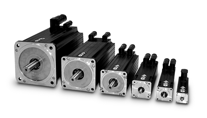
Quiet stable and reliable for long life operation
1.Diameters: 57mm
2.Lengths: 56mm;76mm;96mm
3.Continuous torques: 0.11Nm;0.22Nm;0.32Nm
4.Power: 46W;92W;134W
5.Speeds up to 4000rpm;4000rpm;4000rpm
6.Environmental conditions: -10~+40°C
7.Number of poles/phase:4/3
8.Mangnet material:Bonded NdFeB
9.Insulation class:B
10.Optional: electronic drivers, encoders and gearheads, as well as Hall effect resolver and sensorless feedback
11.We can design the special voltage and shaft and so on
| Application: | Industrial |
|---|---|
| Speed: | High Speed |
| Number of Stator: | Three-Phase |
| Function: | Driving, Control |
| Casing Protection: | Protection Type |
| Number of Poles: | 8 |
| Samples: |
US$ 162/Piece
1 Piece(Min.Order) | |
|---|
| Customization: |
Available
|
|
|---|
Are there common issues or challenges associated with servo motor systems, and how can they be addressed?
Servo motor systems are widely used in various applications, but they can encounter common issues or challenges that affect their performance and reliability. Let’s explore some of these issues and discuss potential solutions:
1. Positioning and Tracking Errors:
One common challenge in servo motor systems is positioning and tracking errors. These errors can occur due to factors such as mechanical backlash, encoder resolution limitations, or disturbances in the system. To address this issue, careful calibration and tuning of the servo control system are necessary. This includes adjusting feedback gains, implementing feedback filtering techniques, and utilizing advanced control algorithms to improve the system’s accuracy and minimize errors. Additionally, employing high-resolution encoders and backlash compensation mechanisms can help enhance the positioning and tracking performance.
2. Vibration and Resonance:
Vibration and resonance can impact the performance of servo motor systems, leading to reduced accuracy and stability. These issues can arise from mechanical resonances within the system or external disturbances. To mitigate vibration and resonance problems, it is crucial to analyze the system’s dynamics and identify critical resonant frequencies. Implementing vibration dampening techniques such as mechanical isolation, using vibration-absorbing materials, or employing active vibration control methods can help minimize the effect of vibrations and improve the system’s performance.
3. Overheating and Thermal Management:
Servo motors can generate heat during operation, and inadequate thermal management can lead to overheating and potential performance degradation. To address this issue, proper cooling and thermal management techniques should be employed. This may involve using heat sinks, fans, or liquid cooling systems to dissipate heat efficiently. Ensuring adequate ventilation and airflow around the motor and avoiding excessive current or overloading can also help prevent overheating. Monitoring the motor’s temperature and implementing temperature protection mechanisms can further safeguard the motor from thermal damage.
4. Electrical Noise and Interference:
Electrical noise and interference can affect the performance and reliability of servo motor systems. These issues can arise from electromagnetic interference (EMI) or radio frequency interference (RFI) from nearby equipment or electrical sources. To mitigate electrical noise, proper shielding and grounding techniques should be employed. Using shielded cables, ferrite cores, and grounding the motor and control system can help minimize the impact of noise and interference. Additionally, employing filtering techniques and surge protection devices can further improve system robustness against electrical disturbances.
5. System Integration and Compatibility:
Integrating a servo motor system into a larger control system or automation setup can present challenges in terms of compatibility and communication. Ensuring proper compatibility between the servo motor and the control system is crucial. This involves selecting appropriate communication protocols, such as EtherCAT or Modbus, and ensuring compatibility with the control signals and interfaces. Employing standardized communication interfaces and protocols can facilitate seamless integration and interoperability. Additionally, thorough testing and verification of the system’s compatibility before deployment can help identify and address any integration issues.
6. Maintenance and Service:
Maintenance and service requirements are important considerations for servo motor systems. Regular maintenance, including lubrication, inspection, and cleaning, can help prevent issues related to wear and tear. Following manufacturer-recommended maintenance schedules and procedures is essential to ensure the longevity and optimal performance of the motor. In case of any malfunctions or failures, having access to technical support from the manufacturer or trained service personnel can help diagnose and address problems effectively.
By being aware of these common issues and challenges associated with servo motor systems and implementing appropriate solutions, it is possible to enhance the performance, reliability, and lifespan of the servo motor system. Regular monitoring, proactive maintenance, and continuous improvement can contribute to optimizing the overall operation and efficiency of the system.
How does the accuracy of a servo motor impact the precision of a system it operates in?
The accuracy of a servo motor has a significant impact on the precision of the system in which it operates. Here’s how the accuracy of a servo motor influences the precision of the system:
1. Positioning Control:
The accuracy of a servo motor directly affects the precision of positioning control in a system. A servo motor with high accuracy can accurately and consistently reach and maintain the desired position. This precision in positioning control is crucial in applications where precise movements, such as in robotics or manufacturing processes, are required. If the servo motor lacks accuracy, it may introduce position errors, leading to reduced precision in the system’s overall operation.
2. Repeatability:
Repeatability refers to the ability of a system to consistently achieve the same position or motion repeatedly. The accuracy of a servo motor plays a vital role in achieving high repeatability. A servo motor with high accuracy will consistently return to the same position when commanded to do so. This level of repeatability is essential in applications where consistent and precise movements are necessary, such as in assembly lines or pick-and-place operations. A lack of accuracy in the servo motor can result in variations in position from one cycle to another, reducing the overall precision of the system.
3. Error Compensation:
The accuracy of a servo motor is crucial for error compensation in a system. In many applications, external factors, such as variations in load or environmental conditions, can introduce errors in the system’s operation. An accurate servo motor can help compensate for these errors by precisely adjusting its position or motion based on feedback from sensors. This error compensation capability contributes to maintaining the precision of the system, as the servo motor can continuously adjust to minimize any deviations from the desired position or trajectory.
4. System Stability:
The accuracy of the servo motor also impacts the stability of the system. A servo motor with high accuracy can achieve stable movements and maintain control over the system’s dynamics. It can respond accurately to control signals, preventing overshoot, oscillations, or erratic behaviors that can degrade system precision. On the other hand, a servo motor with lower accuracy may introduce instability or erratic movements, compromising the overall precision of the system.
5. System Calibration and Calibration:
An accurate servo motor simplifies the calibration and fine-tuning process of a system. When a system requires calibration, an accurate servo motor provides a reliable reference point for adjustments. The precise and consistent movements of the servo motor make it easier to calibrate other components or subsystems in the system, ensuring that the entire system operates with the desired precision. If the servo motor lacks accuracy, it can be challenging to calibrate the system effectively, resulting in reduced precision in the system’s operation.
In summary, the accuracy of a servo motor has a direct impact on the precision of the system it operates in. An accurate servo motor enables precise positioning control, high repeatability, effective error compensation, system stability, and simplified calibration processes. These factors collectively contribute to achieving the desired precision in the system’s operation. Therefore, selecting a servo motor with the appropriate level of accuracy is crucial for ensuring the overall precision and performance of the system.
In which industries are servo motors commonly used, and what applications do they serve?
Servo motors are widely used across various industries due to their precise control capabilities and ability to deliver high torque at different speeds. Here are some industries where servo motors are commonly employed, along with their applications:
1. Robotics:
Servo motors are extensively used in robotics to control the movement of robotic limbs and joints. They enable precise positioning and accurate control, allowing robots to perform tasks with high accuracy and repeatability. Servo motors are also employed in humanoid robots, industrial manipulators, and collaborative robots (cobots).
2. Manufacturing and Automation:
In manufacturing and automation industries, servo motors are used in various applications such as conveyor systems, pick-and-place machines, packaging equipment, and assembly lines. Servo motors provide precise control over the movement of components, ensuring accurate positioning, fast response times, and high throughput.
3. CNC Machining:
Servo motors play a vital role in computer numerical control (CNC) machines, where they control the movement of axes (e.g., X, Y, and Z). These motors enable precise and smooth motion, allowing CNC machines to accurately shape and cut materials such as metal, wood, and plastics. Servo motors are also used in CNC routers, milling machines, lathes, and laser cutting equipment.
4. Aerospace and Aviation:
Servo motors find applications in the aerospace and aviation industries, particularly in flight control systems. They are used to control the movement of aircraft surfaces, such as ailerons, elevators, rudders, and flaps. Servo motors ensure precise and responsive control, contributing to the stability and maneuverability of aircraft.
5. Medical Devices:
In the medical field, servo motors are used in various devices and equipment. They are employed in robotic surgery systems, prosthetics, exoskeletons, infusion pumps, diagnostic equipment, and laboratory automation. Servo motors enable precise and controlled movements required for surgical procedures, rehabilitation, and diagnostic tests.
6. Automotive:
Servo motors have several applications in the automotive industry. They are used in electric power steering systems, throttle control, braking systems, and active suspension systems. Servo motors provide accurate control over steering, acceleration, and braking, enhancing vehicle safety and performance.
7. Entertainment and Motion Control:
Servo motors are widely used in the entertainment industry for animatronics, special effects, and motion control systems. They enable realistic movements of animatronic characters, robotic props, and camera rigs in film, television, and theme park attractions. Servo motors also find applications in motion simulators, gaming peripherals, and virtual reality systems.
In addition to these industries, servo motors are utilized in various other fields, including industrial automation, renewable energy systems, textile machinery, printing and packaging, and scientific research.
Overall, servo motors are versatile components that find widespread use in industries requiring precise motion control, accurate positioning, and high torque output. Their applications span across robotics, manufacturing, CNC machining, aerospace, medical devices, automotive, entertainment, and numerous other sectors.
editor by CX 2023-11-27
China wholesaler 220V 400W 0.4kw 1.27n. M. 3000rpm Single-Phase 80st-M01330 Electric Servo AC Motor with Aasd-15A Driver wholesaler
Product Description
Product Discription
Company Profile
HangZhou Terry Machinery Co.Ltd is a leading supplier of bearings, Linear motion system for CNC , Ball transfer Unit
and transmission component .the growing industrial and Favorable policy of HangZhou benefit the development of Terry
Machinery .Our products are utilized in industrial, motorcycle, vehicle and Automation applications. Now we are exporting
to 46 countries.including USA, GBR , Germany , Spain, Poland ,Turkey ect .The Goal of Terry Machinery to provide out
customers with widest range of products at competitive prices, backed with the best Service.OUR ADVANTAGE Products
Our major products & Supplied:Meet all the international standards and ISO9001 -TS1694 Certificate Big volume in Stock,
No MOQ required Personnel Our salespersons are well trained to accommodate your requests and speak English for your
conveniences.Our technicians and engineers Experience in the Industry area exceeds 23 years Service &Quality control ,
We supply detailed drawings and offer when ever necessary,We help all customers promote and improve their sales.We
inspect every piece of products by ourselves before delivery.
Customer Praise
FAQ
| Number of Stator: | Single-Phase |
|---|---|
| Function: | Driving |
| Brand: | Ntl |
| Rated Current(a): | 2 |
| Rated Speed: | 3000rpm |
| Rated Power: | 400W |
| Samples: |
US$ 250/Piece
1 Piece(Min.Order) | |
|---|
editor by CX 2023-10-19
China Yl90S-2 Asynchronous Motor 220V 5060Hz Ie3 1.5Kw Electric Motor Induction Single Phase Motor car motor
Warranty: Other
Product Number: YL-90S-2
Kind: Asynchronous Motor, YL Sequence solitary-period motor
Frequency: 50/60Hz
Phase: A few-phase
Protect Characteristic: Drip-proof
AC Voltage: 208-230 / 240 V
Efficiency: Ie 3
Voltage: 220V
Certification: CCC/ce/RoHS
Item Title: solitary-stage asynchronous motor
Custom: Acceptance of customization
Key phrases: one-section motor
Product: YL-90S-two
Packaging Particulars: picket box package corton paper pores and skin seriesof industrial electrical power one-phase capacitor running motor ,suited for driving modest lathe pumps only Households with one section energy offer workshop is especially relevant .This collection motor adopts innovative technological innovation layout,using higher top quality,materials Has a good apperance ,sophisticated performance,straightforward upkeep, Large-conclude authentic Germany dunkermotoren electric powered dc door motor reputable,procedure,minimal WenSheng,lownosie ,smallstarting present,beginning this kind of as big torque attributes and in conformity with the related
Port: HangZhou Port/ZheJiang Port
Solution Specifics
| Product name | YL Series solitary-period asynchronous motor |
| Model | YL-90S-two |
| Keywords | single-period asynchronous motor |
| Type | single-section motor |
The Basics of a Planetary Motor
A Planetary Motor is a type of gearmotor that uses multiple planetary gears to deliver torque. This system minimizes the chances of failure of individual gears and increases output capacity. Compared to the planetary motor, the spur gear motor is less complex and less expensive. However, a spur gear motor is generally more suitable for applications requiring low torque. This is because each gear is responsible for the entire load, limiting its torque.
Self-centering planetary gears
This self-centering mechanism for a planetary motor is based on a helical arrangement. The helical structure involves a sun-planet, with its crown and slope modified. The gears are mounted on a ring and share the load evenly. The helical arrangement can be either self-centering or self-resonant. This method is suited for both applications.
A helical planetary gear transmission is illustrated in FIG. 1. A helical configuration includes an output shaft 18 and a sun gear 18. The drive shaft extends through an opening in the cover to engage drive pins on the planet carriers. The drive shaft of the planetary gears can be fixed to the helical arrangement or can be removable. The transmission system is symmetrical, allowing the output shaft of the planetary motor to rotate radially in response to the forces acting on the planet gears.
A flexible pin can improve load sharing. This modification may decrease the face load distribution, but increases the (K_Hbeta) parameter. This effect affects the gear rating and life. It is important to understand the effects of flexible pins. It is worth noting that there are several other disadvantages of flexible pins in helical PGSs. The benefits of flexible pins are discussed below.
Using self-centering planetary gears for a helical planetary motor is essential for symmetrical force distribution. These gears ensure the symmetry of force distribution. They can also be used for self-centering applications. Self-centering planetary gears also guarantee the proper force distribution. They are used to drive a planetary motor. The gearhead is made of a ring gear, and the output shaft is supported by two ball bearings. Self-centering planetary gears can handle a high torque input, and can be suited for many applications.
To solve for a planetary gear mechanism, you need to find its pitch curve. The first step is to find the radius of the internal gear ring. A noncircular planetary gear mechanism should be able to satisfy constraints that can be complex and nonlinear. Using a computer, you can solve for these constraints by analyzing the profile of the planetary wheel’s tooth curve.
High torque
Compared to the conventional planetary motors, high-torque planetary motors have a higher output torque and better transmission efficiency. The high-torque planetary motors are designed to withstand large loads and are used in many types of applications, such as medical equipment and miniature consumer electronics. Their compact design makes them suitable for small space-saving applications. In addition, these motors are designed for high-speed operation.
They come with a variety of shaft configurations and have a wide range of price-performance ratios. The FAULHABER planetary gearboxes are made of plastic, resulting in a good price-performance ratio. In addition, plastic input stage gears are used in applications requiring high torques, and steel input stage gears are available for higher speeds. For difficult operating conditions, modified lubrication is available.
Various planetary gear motors are available in different sizes and power levels. Generally, planetary gear motors are made of steel, brass, or plastic, though some use plastic for their gears. Steel-cut gears are the most durable, and are ideal for applications that require a high amount of torque. Similarly, nickel-steel gears are more lubricated and can withstand a high amount of wear.
The output torque of a high-torque planetary gearbox depends on its rated input speed. Industrial-grade high-torque planetary gearboxes are capable of up to 18000 RPM. Their output torque is not higher than 2000 nm. They are also used in machines where a planet is decelerating. Their working temperature ranges between 25 and 100 degrees Celsius. For best results, it is best to choose the right size for the application.
A high-torque planetary gearbox is the most suitable type of high-torque planetary motor. It is important to determine the deceleration ratio before buying one. If there is no product catalog that matches your servo motor, consider buying a close-fitting high-torque planetary gearbox. There are also high-torque planetary gearboxes available for custom-made applications.
High efficiency
A planetary gearbox is a type of mechanical device that is used for high-torque transmission. This gearbox is made of multiple pairs of gears. Large gears on the output shaft mesh with small gears on the input shaft. The ratio between the big and small gear teeth determines the transmittable torque. High-efficiency planetary gearheads are available for linear motion, axial loads, and sterilizable applications.
The AG2400 high-end gear unit series is ideally matched to Beckhoff’s extensive line of servomotors and gearboxes. Its single-stage and multi-stage transmission ratios are highly flexible and can be matched to different robot types. Its modified lubrication helps it operate in difficult operating conditions. These high-performance gear units are available in a wide range of sizes.
A planetary gear motor can be made of steel, nickel-steel, or brass. In addition to steel, some models use plastic. The planetary gears share work between multiple gears, making it easy to transfer high amounts of power without putting a lot of stress on the gears. The gears in a planetary gear motor are held together by a movable arm. High-efficiency planetary gear motors are more efficient than traditional gearmotors.
While a planetary gear motor can generate torque, it is more efficient and cheaper to produce. The planetary gear system is designed with all gears operating in synchrony, minimizing the chance of a single gear failure. The efficiency of a planetary gearmotor makes it a popular choice for high-torque applications. This type of motor is suitable for many applications, and is less expensive than a standard geared motor.
The planetary gearbox is a combination of a planetary type gearbox and a DC motor. The planetary gearbox is compact, versatile, and efficient, and can be used in a wide range of industrial environments. The planetary gearbox with an HN210 DC motor is used in a 22mm OD, PPH, and ph configuration with voltage operating between 6V and 24V. It is available in many configurations and can be custom-made to meet your application requirements.
High cost
In general, planetary gearmotors are more expensive than other configurations of gearmotors. This is due to the complexity of their design, which involves the use of a central sun gear and a set of planetary gears which mesh with each other. The entire assembly is enclosed in a larger internal tooth gear. However, planetary motors are more effective for higher load requirements. The cost of planetary motors varies depending on the number of gears and the number of planetary gears in the system.
If you want to build a planetary gearbox, you can purchase a gearbox for the motor. These gearboxes are often available with several ratios, and you can use any one to create a custom ratio. The cost of a gearbox depends on how much power you want to move with the gearbox, and how much gear ratio you need. You can even contact your local FRC team to purchase a gearbox for the motor.
Gearboxes play a major role in determining the efficiency of a planetary gearmotor. The output shafts used for this type of motor are usually made of steel or nickel-steel, while those used in planetary gearboxes are made from brass or plastic. The former is the most durable and is best for applications that require high torque. The latter, however, is more absorbent and is better at holding lubricant.
Using a planetary gearbox will allow you to reduce the input power required for the stepper motor. However, this is not without its downsides. A planetary gearbox can also be replaced with a spare part. A planetary gearbox is inexpensive, and its spare parts are inexpensive. A planetary gearbox has low cost compared to a planetary motor. Its advantages make it more desirable in certain applications.
Another advantage of a planetary gear unit is the ability to handle ultra-low speeds. Using a planetary gearbox allows stepper motors to avoid resonance zones, which can cause them to crawl. In addition, the planetary gear unit allows for safe and efficient cleaning. So, whether you’re considering a planetary gear unit for a particular application, these gear units can help you get exactly what you need.
editor by czh 2023-02-21
China high quality single-phase motor ac induction electric motor Capacitor Sart And Run 0.5hp 0.75hp 1hp 1.5hp 2hp 3hp 4hp 5.5hp 50 dc motor
Guarantee: 3months-1year
Design Quantity: YL Series
Kind: Asynchronous Motor
Frequency: fifty/60Hz, 50hz,60hz and fifty/60hz
Section: Solitary-section
Shield Characteristic: Entirely Enclosed
AC Voltage: AC, or 220-240v, a hundred and ten-127v AC
Efficiency: IE two
Voltage: 220~240V,one hundred~110V or on your ask for
Use:: Common
Pace:: Consistent Velocity
M:: B3/B5/B14/B15/B34/B35
OEM Services:: Acknowledge
Obligation:: S1
Cooling strategy:: IC411
Section:: one-section
Certification: CCC, ce
Packaging Details: 1pc/pp bag, carton for outsdie packing.
Port: HangZhou/ZheJiang
Advise Merchandise
| color | ordered |
| material | cast iron |
| voltage | ordered |
The Basics of a Planetary Motor
A Planetary Motor is a type of gearmotor that uses multiple planetary gears to deliver torque. This system minimizes the chances of failure of individual gears and increases output capacity. Compared to the planetary motor, the spur gear motor is less complex and less expensive. However, a spur gear motor is generally more suitable for applications requiring low torque. This is because each gear is responsible for the entire load, limiting its torque.
Self-centering planetary gears
This self-centering mechanism for a planetary motor is based on a helical arrangement. The helical structure involves a sun-planet, with its crown and slope modified. The gears are mounted on a ring and share the load evenly. The helical arrangement can be either self-centering or self-resonant. This method is suited for both applications.
A helical planetary gear transmission is illustrated in FIG. 1. A helical configuration includes an output shaft 18 and a sun gear 18. The drive shaft extends through an opening in the cover to engage drive pins on the planet carriers. The drive shaft of the planetary gears can be fixed to the helical arrangement or can be removable. The transmission system is symmetrical, allowing the output shaft of the planetary motor to rotate radially in response to the forces acting on the planet gears.
A flexible pin can improve load sharing. This modification may decrease the face load distribution, but increases the (K_Hbeta) parameter. This effect affects the gear rating and life. It is important to understand the effects of flexible pins. It is worth noting that there are several other disadvantages of flexible pins in helical PGSs. The benefits of flexible pins are discussed below.
Using self-centering planetary gears for a helical planetary motor is essential for symmetrical force distribution. These gears ensure the symmetry of force distribution. They can also be used for self-centering applications. Self-centering planetary gears also guarantee the proper force distribution. They are used to drive a planetary motor. The gearhead is made of a ring gear, and the output shaft is supported by two ball bearings. Self-centering planetary gears can handle a high torque input, and can be suited for many applications.
To solve for a planetary gear mechanism, you need to find its pitch curve. The first step is to find the radius of the internal gear ring. A noncircular planetary gear mechanism should be able to satisfy constraints that can be complex and nonlinear. Using a computer, you can solve for these constraints by analyzing the profile of the planetary wheel’s tooth curve.
High torque
Compared to the conventional planetary motors, high-torque planetary motors have a higher output torque and better transmission efficiency. The high-torque planetary motors are designed to withstand large loads and are used in many types of applications, such as medical equipment and miniature consumer electronics. Their compact design makes them suitable for small space-saving applications. In addition, these motors are designed for high-speed operation.
They come with a variety of shaft configurations and have a wide range of price-performance ratios. The FAULHABER planetary gearboxes are made of plastic, resulting in a good price-performance ratio. In addition, plastic input stage gears are used in applications requiring high torques, and steel input stage gears are available for higher speeds. For difficult operating conditions, modified lubrication is available.
Various planetary gear motors are available in different sizes and power levels. Generally, planetary gear motors are made of steel, brass, or plastic, though some use plastic for their gears. Steel-cut gears are the most durable, and are ideal for applications that require a high amount of torque. Similarly, nickel-steel gears are more lubricated and can withstand a high amount of wear.
The output torque of a high-torque planetary gearbox depends on its rated input speed. Industrial-grade high-torque planetary gearboxes are capable of up to 18000 RPM. Their output torque is not higher than 2000 nm. They are also used in machines where a planet is decelerating. Their working temperature ranges between 25 and 100 degrees Celsius. For best results, it is best to choose the right size for the application.
A high-torque planetary gearbox is the most suitable type of high-torque planetary motor. It is important to determine the deceleration ratio before buying one. If there is no product catalog that matches your servo motor, consider buying a close-fitting high-torque planetary gearbox. There are also high-torque planetary gearboxes available for custom-made applications.
High efficiency
A planetary gearbox is a type of mechanical device that is used for high-torque transmission. This gearbox is made of multiple pairs of gears. Large gears on the output shaft mesh with small gears on the input shaft. The ratio between the big and small gear teeth determines the transmittable torque. High-efficiency planetary gearheads are available for linear motion, axial loads, and sterilizable applications.
The AG2400 high-end gear unit series is ideally matched to Beckhoff’s extensive line of servomotors and gearboxes. Its single-stage and multi-stage transmission ratios are highly flexible and can be matched to different robot types. Its modified lubrication helps it operate in difficult operating conditions. These high-performance gear units are available in a wide range of sizes.
A planetary gear motor can be made of steel, nickel-steel, or brass. In addition to steel, some models use plastic. The planetary gears share work between multiple gears, making it easy to transfer high amounts of power without putting a lot of stress on the gears. The gears in a planetary gear motor are held together by a movable arm. High-efficiency planetary gear motors are more efficient than traditional gearmotors.
While a planetary gear motor can generate torque, it is more efficient and cheaper to produce. The planetary gear system is designed with all gears operating in synchrony, minimizing the chance of a single gear failure. The efficiency of a planetary gearmotor makes it a popular choice for high-torque applications. This type of motor is suitable for many applications, and is less expensive than a standard geared motor.
The planetary gearbox is a combination of a planetary type gearbox and a DC motor. The planetary gearbox is compact, versatile, and efficient, and can be used in a wide range of industrial environments. The planetary gearbox with an HN210 DC motor is used in a 22mm OD, PPH, and ph configuration with voltage operating between 6V and 24V. It is available in many configurations and can be custom-made to meet your application requirements.
High cost
In general, planetary gearmotors are more expensive than other configurations of gearmotors. This is due to the complexity of their design, which involves the use of a central sun gear and a set of planetary gears which mesh with each other. The entire assembly is enclosed in a larger internal tooth gear. However, planetary motors are more effective for higher load requirements. The cost of planetary motors varies depending on the number of gears and the number of planetary gears in the system.
If you want to build a planetary gearbox, you can purchase a gearbox for the motor. These gearboxes are often available with several ratios, and you can use any one to create a custom ratio. The cost of a gearbox depends on how much power you want to move with the gearbox, and how much gear ratio you need. You can even contact your local FRC team to purchase a gearbox for the motor.
Gearboxes play a major role in determining the efficiency of a planetary gearmotor. The output shafts used for this type of motor are usually made of steel or nickel-steel, while those used in planetary gearboxes are made from brass or plastic. The former is the most durable and is best for applications that require high torque. The latter, however, is more absorbent and is better at holding lubricant.
Using a planetary gearbox will allow you to reduce the input power required for the stepper motor. However, this is not without its downsides. A planetary gearbox can also be replaced with a spare part. A planetary gearbox is inexpensive, and its spare parts are inexpensive. A planetary gearbox has low cost compared to a planetary motor. Its advantages make it more desirable in certain applications.
Another advantage of a planetary gear unit is the ability to handle ultra-low speeds. Using a planetary gearbox allows stepper motors to avoid resonance zones, which can cause them to crawl. In addition, the planetary gear unit allows for safe and efficient cleaning. So, whether you’re considering a planetary gear unit for a particular application, these gear units can help you get exactly what you need.
editor by czh 2023-02-19
China 110v 220v 40w single phase electric motor with speed controller 5GN7.5K motor driver
Warranty: 1 yr
Model Number: 5IK40RGN-C,5GN7.5K
Sort: Asynchronous Motor
Frequency: fifty/60hz
Phase: Solitary-period
Safeguard Characteristic: Totally Enclosed
AC Voltage: 220V
Effectiveness: E
Dimension: 90mm (60,70,80,90mm)
Equipment type: 12(10/twelve/15mm) diameter shaft
Gear shaft: screw/cylindrical shaft
Output Power: 40w (6w~180w)
Ratio of Equipment box: 1/7.5 (1/3–1/a hundred and eighty)
Fat: .5kg ~5kg
Accessorries: brake, bracket, speed controller, terminal box
Packaging Specifics: carton, picket box chosen
Port: HangZhou, HangZhou town
Overview
| <FONT size="4" confront="Instances New Roman, Instances" color="#, 571- 7016978, 571- 7301608, Fax: 86~/8822 0571 -7017968 <FONT face="Times New Roman, Times" color="#ff59200493 FAQ Q1: What is the payment phrases? A: T/T, L/C, PAYPAL, WESTERN UNION, Credit rating CARD, Cash. Q2. What is your shipping time?A: 1-5 days after payment. Q3. What is your phrases of delivery?A: EXW, FOB, CFR, CIF, DDU.DDP.Q5. What is your creation ability?A: About 3000 PCS for each thirty day period. Q6: What you can do if we stll have inquiries on items? A: We afford samples for tests, if approval then negotiate cooperation. Q7: How do you make our company prolonged-term and great connection?A:1. We maintain great high quality and aggressive value to ensure our clients benefit LDK UE205 Wider interior ring Gcr15 metal deep groove insert ball bearings 2. We regard each and every customer as our friend and we sincerely do company and make pals with them.
The Basics of a Planetary MotorA Planetary Motor is a type of gearmotor that uses multiple planetary gears to deliver torque. This system minimizes the chances of failure of individual gears and increases output capacity. Compared to the planetary motor, the spur gear motor is less complex and less expensive. However, a spur gear motor is generally more suitable for applications requiring low torque. This is because each gear is responsible for the entire load, limiting its torque. Self-centering planetary gearsThis self-centering mechanism for a planetary motor is based on a helical arrangement. The helical structure involves a sun-planet, with its crown and slope modified. The gears are mounted on a ring and share the load evenly. The helical arrangement can be either self-centering or self-resonant. This method is suited for both applications. High torqueCompared to the conventional planetary motors, high-torque planetary motors have a higher output torque and better transmission efficiency. The high-torque planetary motors are designed to withstand large loads and are used in many types of applications, such as medical equipment and miniature consumer electronics. Their compact design makes them suitable for small space-saving applications. In addition, these motors are designed for high-speed operation. High efficiencyA planetary gearbox is a type of mechanical device that is used for high-torque transmission. This gearbox is made of multiple pairs of gears. Large gears on the output shaft mesh with small gears on the input shaft. The ratio between the big and small gear teeth determines the transmittable torque. High-efficiency planetary gearheads are available for linear motion, axial loads, and sterilizable applications. High costIn general, planetary gearmotors are more expensive than other configurations of gearmotors. This is due to the complexity of their design, which involves the use of a central sun gear and a set of planetary gears which mesh with each other. The entire assembly is enclosed in a larger internal tooth gear. However, planetary motors are more effective for higher load requirements. The cost of planetary motors varies depending on the number of gears and the number of planetary gears in the system.
China 0.75kw 1hp single phase electric ac asynchronous motor wholesalerWarranty: 3months-1year Product Overview YC series single phase electric motorsYC series motor is a kind of capacitive single-phase asynchronous motor derived from YE2 series three-phase asynchronous motor.Its corresponding relationship of frame size, installation size and power level is the same as YE2 series three-phase asynchronousmotor. This series of motors are highly efficient, energy-saving, high starting torque, low noise, low vibration, safe andreliable operation. It is widely used in refrigerators, pumps, fans, small machine tools, agricultural and sideline productsprocessing and household appliances. FEATURES AT A GLANCE COMPACT DIMENSIONSEXTENDING UNDERCARRIAGE SAFETY FRAMESIMPLE CONTROLSEASY MAINTENANCEVERSATILITYEXTENDING UNDERCARRIAGE MS 3 phase aluminum house motor YEJ 3 phase Brake motor ANP GOST 3 phase MOTOR PRODUCT SPECIFICATIONS
Benefits of a Planetary MotorBesides being one of the most efficient forms of a drive, a Planetary Motor also offers a great number of other benefits. These features enable it to create a vast range of gear reductions, as well as generate higher torques and torque density. Let’s take a closer look at the benefits this mechanism has to offer. To understand what makes it so appealing, we’ll explore the different types of planetary systems. Solar gearThe solar gear on a planetary motor has two distinct advantages. It produces less noise and heat than a helical gear. Its compact footprint also minimizes noise. It can operate at high speeds without sacrificing efficiency. However, it must be maintained with constant care to operate efficiently. Solar gears can be easily damaged by water and other debris. Solar gears on planetary motors may need to be replaced over time. Sun gearThe mechanical arrangement of a planetary motor comprises of two components: a ring gear and a sun gear. The ring gear is fixed to the motor’s output shaft, while the sun gear rolls around and orbits around it. The ring gear and sun gear are linked by a planetary carrier, and the torque they produce is distributed across their teeth. The planetary structure arrangement also reduces backlash, and is critical to achieve a quick start and stop cycle. Planetary gearA planetary motor gear works by distributing rotational force along a separating plate and a cylindrical shaft. A shock-absorbing device is included between the separating plate and cylindrical shaft. This depressed portion prevents abrasion wear and foreign particles from entering the device. The separating plate and shaft are positioned coaxially. In this arrangement, the input shaft and output shaft are rotated relative to one another. The rotatable disc absorbs the impact. Planetary gearboxA planetary motor and gearbox are a common combination of electric and mechanical power sources. They share the load of rotation between multiple gear teeth to increase the torque capacity. This design is also more rigid, with low backlash that can be as low as one or two arc minutes. The advantages of a planetary gearmotor over a conventional electric motor include compact size, high efficiency, and less risk of gear failure. Planetary gear motors are also more reliable and durable than conventional electric motors. Planetary gear motorPlanetary gear motors reduce the rotational speed of an armature by one or more times. The reduction ratio depends on the structure of the planetary gear device. The planetary gear device has an output shaft and an armature shaft. A separating plate separates the two. The output shaft moves in a circular pattern to turn the pinion 3. When the pinion rotates to the engagement position, it is engaged with the ring gear 4. The ring gear then transmits the rotational torque to the armature shaft. The result is that the engine cranks up.
China 0.75kw 1hp single phase electric ac asynchronous motor motor brushesWarranty: 3months-1year Product Overview YC series single phase electric motorsYC series motor is a kind of capacitive single-phase asynchronous motor derived from YE2 series three-phase asynchronous motor.Its corresponding relationship of frame size, installation size and power level is the same as YE2 series three-phase asynchronousmotor. This series of motors are highly efficient, energy-saving, high starting torque, low noise, low vibration, safe andreliable operation. It is widely used in refrigerators, pumps, fans, small machine tools, agricultural and sideline productsprocessing and household appliances. FEATURES AT A GLANCE COMPACT DIMENSIONSEXTENDING UNDERCARRIAGE SAFETY FRAMESIMPLE CONTROLSEASY MAINTENANCEVERSATILITYEXTENDING UNDERCARRIAGE MS 3 phase aluminum house motor YEJ 3 phase Brake motor ANP GOST 3 phase MOTOR PRODUCT SPECIFICATIONS
How to Assemble a Planetary MotorA Planetary Motor uses multiple planetary surfaces to produce torque and rotational speed. The planetary system allows for a wide range of gear reductions. Planetary systems are particularly effective in applications where higher torques and torque density are needed. As such, they are a popular choice for electric vehicles and other applications where high-speed mobility is required. Nevertheless, there are many benefits associated with using a planetary motor. Read on to learn more about these motors. VPLiteIf you’re looking to replace the original VP, the VPLite has a similar output shaft as the original. This means that you can mix and match your original gear sets, including the input and output shafts. You can even mix metal inputs with plastic outputs. Moreover, if you decide to replace the gearbox, you can easily disassemble the entire unit and replace it with a new one without losing any output torque. VersaPlanetaryThe VersaPlanetary is a highly versatile planetary motor that can be mounted in a variety of ways. Its unique design includes a removable shaft coupler system that makes it simple to swap out the motor with another. This planetary motor mounts in any position where a CIM motor mounts. Here’s how to assemble the motor. First, remove the hex output shaft from the VersaPlanetary output stage. Its single ring clip holds it in place. You can use a drill press to drill a hole into the output shaft. Self-centering planetary gearsA planetary motor is a simple mechanical device that rotates around a axis, with the planets moving around the shaft in a radial direction. The planets are positioned so that they mesh with both the sun gear and the output gears. The carrier 48 is flexibly connected to the drive shaft and can move depending on the forces exerted by the planet gears. In this way, the planets can always be in the optimal mesh with the output gears and sun gear. EncodersA planetary geared motor is a DC motor with a planetary gearbox. The motor can be used to drive heavy loads and has a ratio of 104:1. The shaft speed is 116rpm when it is unloaded. A planetary gearbox has a low backlash and is often used in applications that need high torque. Planetary Motor encoders can help you keep track of your robot’s position or speed. CostThere are several advantages of planetary motors. One of the biggest is their cost, but they can also be used in many different applications. They can be combined with a variety of gearboxes, and are ideal for various types of robots, laboratory automation, and production applications. Planetary gearboxes are available in many different materials, and plastic planetary gearboxes are an economical alternative. Plastic gearboxes reduce noise at higher speeds, and steel input stage gears are available for high torques. A modified lubrication system can help with difficult operating conditions. ApplicationsThere are several different applications of the planetary motor. One such application is in motion control. Planetary gearboxes have many benefits, including high torque, low backlash, and torsional stiffness. They also have an extremely compact design, and can be used for a variety of applications, from rack and pinion drives to delta robotics. In many cases, they are less expensive to manufacture and use than other types of motors.
| |||||||||||||||||||||||||||||||||||||||||||||||||||||||||||||||||||||||||||||||||||||||||||


