Product Description
Product Description
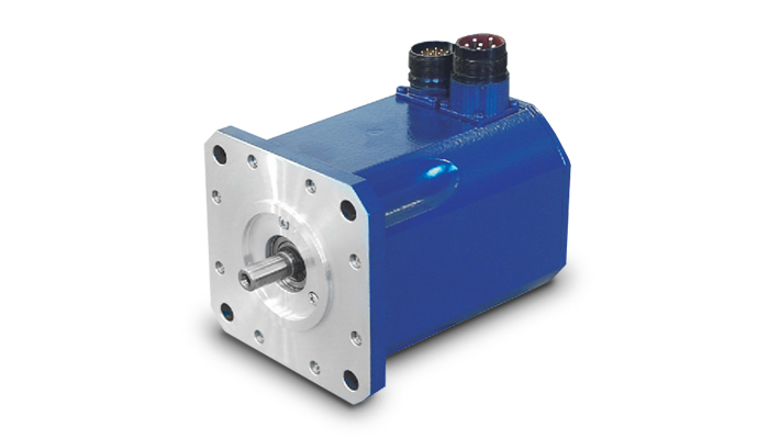
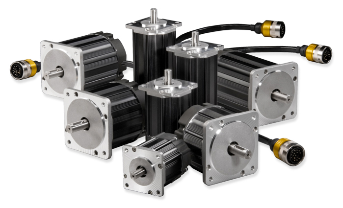
Detailed Photos
Product Parameters
|
Name |
High Precision Planetary Gearbox |
|
Model |
AB042, AB060, AB060A, AB090A, AB115, AB142, AB180, AB220 |
|
Gearing Arrangement |
Planetary |
|
Effeiency withfull load |
≥97 |
|
Backlash |
≤5 |
|
Weight |
0.5~48kg |
|
Gear Type |
Helical Gear |
|
Gear stages |
1 stage, 2 stage |
|
Rated Torque |
14N.m-2000N.m |
|
Gear Ratio One-stage |
3, 4, 5, 6, 7, 8, 9, 10 |
|
Gear Ratio Two-stage |
15, 20, 25, 30, 35, 40, 45, 50, 60, 70, 80, 90, 100 |
|
Mounting Position |
Horizontal (foot mounted) or Vertical (flange mounted) |
|
Usage |
stepper motor, servo motor, AC motor, DC motor, etc |
features:
AB-series reducer features:
1. Helical gear design The reduction mechanism adopts the helical gear design, and its tooth shape meshing rate is more than twice that of the general spur gear, and has the characteristics of smooth operation, low noise, high output torque and low backlash
2. Collet type locking mechanism The connection between the input end and the motor adopts a collet-type locking mechanism and undergoes dynamic balance analysis to ensure the concentricity of the joint interface and zero-backlash power transmission at high input speeds
3. Modular design of motor connection board The unique modular design of the motor connecting plate and shaft is suitable for any brand and type of servo motor;
4. Efficient surface treatment technology The surface of the gearbox is treated with electroless nickel, and the connecting plate of the motor is treated with black anodic treatment to improve the environmental tolerance and corrosion resistance
5. One-piece gearbox body The gearbox and the inner ring gear adopt an integrated design, with compact structure, high precision and large output torque
6. Accurate concentricity of gear bar The sun gear made of the whole gear bar has strong rigidity and accurate concentricity
7. Solid, Single piece sun gear construction obtains precise concentricity with increased strength and rigidity. 8.Precision taper roller bearing support to increases radial and axial loading capacity.
Applications
Certifications
Packaging & Shipping
| Hardness: | Hardened Tooth Surface |
|---|---|
| Installation: | Vertical Type |
| Layout: | Coaxial |
| Gear Shape: | Planetary |
| Step: | Single-Step |
| Type: | Ab Series Gearbox, Gear Reducer |
| Samples: |
US$ 100/Piece
1 Piece(Min.Order) | |
|---|
How does the cost of servo motors vary based on their specifications and features?
The cost of servo motors can vary significantly based on their specifications and features. Several factors influence the price of servo motors, and understanding these factors can help in selecting the most cost-effective option for a specific application. Let’s explore in detail how the cost of servo motors can vary:
1. Power Rating:
One of the primary factors affecting the cost of a servo motor is its power rating, which is typically measured in watts or kilowatts. Higher power-rated servo motors generally cost more than lower-rated ones due to the increased materials and manufacturing required to handle higher power levels. The power rating of a servo motor is determined by the torque and speed requirements of the application. Higher torque and speed capabilities often correspond to higher costs.
2. Torque and Speed:
The torque and speed capabilities of a servo motor directly impact its cost. Servo motors designed for high torque and high-speed applications tend to be more expensive due to the need for robust construction, specialized materials, and advanced control electronics. Motors with higher torque and speed ratings often require more powerful magnets, larger windings, and higher precision components, contributing to the increase in cost.
3. Frame Size:
The physical size or frame size of a servo motor also plays a role in determining its cost. Servo motors come in various frame sizes, such as NEMA (National Electrical Manufacturers Association) standard sizes in North America. Larger frame sizes generally command higher prices due to the increased materials and manufacturing complexity required to build larger motors. Smaller frame sizes, on the other hand, may be more cost-effective but may have limitations in terms of torque and speed capabilities.
4. Feedback Mechanism:
The feedback mechanism used in a servo motor affects its cost. Servo motors typically employ encoders or resolvers to provide feedback on the rotor position. Higher-resolution encoders or more advanced feedback technologies can increase the cost of the motor. For example, servo motors with absolute encoders, which provide position information even after power loss, tend to be more expensive than those with incremental encoders.
5. Control Features and Technology:
The control features and technology incorporated into a servo motor can influence its cost. Advanced servo motors may offer features such as built-in controllers, fieldbus communication interfaces, advanced motion control algorithms, or integrated safety functions. These additional features contribute to the cost of the motor but can provide added value and convenience in certain applications. Standard servo motors with basic control functionality may be more cost-effective for simpler applications.
6. Brand and Reputation:
The brand and reputation of the servo motor manufacturer can impact its cost. Established and reputable brands often command higher prices due to factors such as quality assurance, reliability, technical support, and extensive product warranties. While motors from less-known or generic brands may be more affordable, they may not offer the same level of performance, reliability, or long-term support.
7. Customization and Application-Specific Requirements:
If a servo motor needs to meet specific customization or application-specific requirements, such as specialized mounting options, environmental sealing, or compliance with industry standards, the cost may increase. Customization often involves additional engineering, design, and manufacturing efforts, which can lead to higher prices compared to off-the-shelf servo motors.
It’s important to note that the cost of a servo motor is not the sole indicator of its quality or suitability for a particular application. It is essential to carefully evaluate the motor’s specifications, features, and performance characteristics in relation to the application requirements to make an informed decision.
In summary, the cost of servo motors varies based on factors such as power rating, torque and speed capabilities, frame size, feedback mechanism, control features and technology, brand reputation, and customization requirements. By considering these factors and comparing different options, it is possible to select a servo motor that strikes the right balance between performance and cost-effectiveness for a specific application.
Can you explain the concept of torque and speed in relation to servo motors?
Torque and speed are two essential parameters in understanding the performance characteristics of servo motors. Let’s explore these concepts in relation to servo motors:
Torque:
Torque refers to the rotational force produced by a servo motor. It determines the motor’s ability to generate rotational motion and overcome resistance or load. Torque is typically measured in units of force multiplied by distance, such as Nm (Newton-meter) or oz-in (ounce-inch).
The torque output of a servo motor is crucial in applications where the motor needs to move or control a load. The motor must provide enough torque to overcome the resistance or friction in the system and maintain the desired position or motion. Higher torque allows the motor to handle heavier loads or more challenging operating conditions.
It is important to note that the torque characteristics of a servo motor may vary depending on the speed or position of the motor. Manufacturers often provide torque-speed curves or torque-position curves, which illustrate the motor’s torque capabilities at different operating points. Understanding these curves helps in selecting a servo motor that can deliver the required torque for a specific application.
Speed:
Speed refers to the rotational velocity at which a servo motor operates. It indicates how fast the motor can rotate and how quickly it can achieve the desired position or motion. Speed is typically measured in units of revolutions per minute (RPM) or radians per second (rad/s).
The speed of a servo motor is crucial in applications that require rapid movements or high-speed operations. It determines the motor’s responsiveness and the system’s overall performance. Different servo motors have different speed capabilities, and the maximum achievable speed is often specified by the manufacturer.
It is worth noting that the speed of a servo motor may also affect its torque output. Some servo motors exhibit a phenomenon known as “speed-torque curve,” where the motor’s torque decreases as the speed increases. This behavior is influenced by factors such as motor design, winding resistance, and control algorithms. Understanding the speed-torque characteristics of a servo motor is important for selecting a motor that can meet the speed requirements of the application while maintaining sufficient torque.
Overall, torque and speed are interrelated parameters that determine the performance capabilities of a servo motor. The torque capability determines the motor’s ability to handle loads, while the speed capability determines how quickly the motor can achieve the desired motion. When selecting a servo motor, it is essential to consider both the torque and speed requirements of the application to ensure that the motor can deliver the desired performance.

What are the key advantages of using servo motors in industrial applications?
Servo motors offer several key advantages that make them highly beneficial for a wide range of industrial applications. Here are some of the main advantages of using servo motors:
1. Precise Positioning:
Servo motors excel at precise positioning control. They can accurately move to specific angles or positions with high repeatability. This level of precision is crucial in applications where accurate and consistent positioning is required, such as robotics, CNC machining, and assembly lines.
2. High Torque at Various Speeds:
Servo motors are designed to deliver high torque output across a range of speeds. They can generate significant torque even at low speeds, enabling efficient operation in applications that require both high torque and precise control, such as lifting heavy loads or performing intricate movements.
3. Fast Response Times:
Servo motors have fast response times, meaning they can quickly accelerate, decelerate, and change direction in response to control signals. This responsiveness is essential in applications where rapid and dynamic motion control is needed, such as industrial automation, robotics, and production line equipment.
4. Closed-Loop Control:
Servo motors operate in a closed-loop control system, where feedback from position sensors is continuously used to adjust the motor’s behavior. This feedback control mechanism enables accurate tracking of the desired position and compensates for any disturbances or variations that may occur during operation. It enhances the motor’s accuracy, stability, and performance.
5. Wide Range of Sizes and Power Ratings:
Servo motors are available in a wide range of sizes and power ratings, making them suitable for diverse industrial applications. Whether it’s a small motor for precision tasks or a large motor for heavy-duty operations, there are servo motor options to meet various requirements.
6. Energy Efficiency:
Servo motors are designed to be energy-efficient. They typically have high power density, which means they can deliver a significant amount of torque per unit of size and weight. This efficiency helps reduce power consumption, lowers operating costs, and contributes to a greener and more sustainable industrial environment.
7. Flexibility and Adaptability:
Due to their versatility, servo motors can be easily integrated into different systems and applications. They can be combined with various control systems, sensors, and communication protocols to provide seamless integration and compatibility with existing industrial setups. This flexibility allows for customized and scalable solutions tailored to specific industrial requirements.
8. Durability and Reliability:
Servo motors are known for their durability and reliability, even in demanding industrial environments. They are built to withstand harsh conditions such as high temperatures, vibrations, and dust. This robust construction ensures long-term operation and minimizes downtime, contributing to increased productivity and reduced maintenance costs.
In summary, the key advantages of using servo motors in industrial applications include precise positioning, high torque at various speeds, fast response times, closed-loop control for accuracy and stability, a wide range of sizes and power ratings, energy efficiency, flexibility, and durability. These advantages make servo motors highly valuable for industries that require precise motion control, such as robotics, manufacturing, automation, CNC machining, and many others.


editor by CX 2023-11-17
China Standard Planetary Electrical Motor Squre Type 60mm AC Gear and Induction Motor brushless motor
Product Description
TaiBang Motor Industry Group Co., Ltd.
The main products is induction motor, reversible motor, DC brush gear motor, DC brushless gear motor, CH/CV big gear motors, Planetary gear motor ,Worm gear motor etc, which used widely in various fields of manufacturing pipelining, transportation, food, medicine, printing, fabric, packing, office, apparatus, entertainment etc, and is the preferred and matched product for automatic machine.
Motor Model Instruction
5RK40GN-CM
| 5 | R | K | 40 | R | GN | C | M |
| Frame Size | Type | Motor series | Power | Speed Control Motor |
Shaft Type | Voltage | Accessory |
| 2:60mm
3:70mm 4:80mm 5:90mm 6:104mm |
I:Induction
R:Reversible T:Torque |
K series | 6W
15W 25W 40W 60W 90W 120W 140W 180W 200W |
A:Round Shaft
GN:Bevel Gear Shaft GU:Bevel Gear Shaft |
A:Single Phase 110V
C:Single Phase 220V S:3-Phase 220V S3:3-Phase 380V S4:3-Phase 440V |
T/P:Thermally Protected
F:Fan M:Electro-magnetic |
Gear Head Model Instruction
5GN-100K
| 5 | GN | 100 | K | |
| Frame Size | Shaft Type | Gear Reduction Ratio | Bearing Type | Other information |
| 2:60mm
3:70mm 4:80mm 5:90mm 6:104mm |
GN:Bevel Gear Shaft (60#,70#,80#,90# reduction gear head) GU:Bevel Gear Shaft GM:Intermediate Gear Head GS:Gearhead with ears |
1:100 | K:Standard Rolling Bearing
RT:Right Angle With Axile RC:Right Angle With Hollow Shaft |
Sch as shaft diameter,shaft length,etc. |
Specification of motor 40W 90mm Fixed speed AC gear motor
| Type | Gear Tooth Output Shaft | Power (W) |
Frequency (Hz) |
Voltage (V) |
Current (A) |
Start Torque (g.cm) |
Rated | Gearbox Type | ||
| Torque (g.cm) |
Speed (rpm) |
Bearing Gearbox | Middle Gearbox | |||||||
| Reversible Motor | 5RK40GN-C | 40 | 50 | 220 | 0.45 | 3000 | 3000 | 1300 | 5GN/GU-K | 5GN10X |
| 40 | 60 | 220 | 0.41 | 2500 | 2515 | 1550 | 5GN/GU-K | 5GN10X | ||
Gear Head Torque Table(Kg.cm) (kg.cm×9.8÷100)=N.m
| Output Speed :RPM | 500 | 300 | 200 | 150 | 120 | 100 | 75 | 60 | 50 | 30 | 20 | 15 | 10 | 7.5 | 6 | 5 | 3 | ||
| Speed Ratio | 50Hz | 3 | 5 | 7.5 | 10 | 12.5 | 15 | 20 | 25 | 30 | 50 | 75 | 100 | 150 | 200 | 250 | 300 | 500 | |
| 60Hz | 3.6 | 6 | 9 | 15 | 18 | 30 | 36 | 60 | 90 | 120 | 180 | 300 | 360 | 600 | |||||
| Allowed Torque |
40W | kg.cm | 6.7 | 11 | 16 | 21.3 | 28 | 33 | 42 | 54 | 65 | 108 | 150 | 150 | 150 | 150 | 150 | 150 | 150 |
| 60W | kg.cm | 10 | 16 | 24 | 32 | 40 | 48 | 64 | 77 | 93 | 150 | 150 | 150 | 150 | 150 | 150 | 150 | 150 | |
| 90W | kg.cm | 14 | 23 | 35 | 46 | 58 | 69 | 92 | 110 | 133 | 200 | 200 | 200 | 200 | 200 | 200 | 200 | 200 | |
| 120W | kg.cm | 19 | 30.7 | 46 | 61 | 77 | 92 | 123 | 147 | 177 | 200 | 200 | 200 | 200 | 200 | 200 | 200 | 200 | |
| Note: Speed figures are based on synchronous speed, The actual output speed, under rated torque conditions, is about 10-20% less than synchronous speed, a grey background indicates output shaft of geared motor rotates in the same direction as output shaft of motor. A white background indicates rotates rotation in the opposite direction. | |||||||||||||||||||
Drawing:5RK40GN-C/5GN3~20K(Short gearbox shell 43mm)
Drawing:5RK40GN-C/5GN25~180K(Short gearbox shell 61mm)
Above drawing is for standard screw hole.If need through hole, terminal box, or electronic magnet brake, need to tell the seller.
Connection Diagram:
| Application: | Industrial |
|---|---|
| Speed: | Constant Speed |
| Number of Stator: | Single-Phase |
| Function: | Driving, Control |
| Casing Protection: | Closed Type |
| Number of Poles: | 4 |
| Samples: |
US$ 50/Piece
1 Piece(Min.Order) | |
|---|
| Customization: |
Available
| Customized Request |
|---|

The Benefits of Using a Gear Motor
A gear motor works on the principle of conservation of angular momentum. As the smaller gear covers more RPM and the larger gear produces more torque, the ratio between the two is greater than one. Similarly, a multiple gear motor follows the principle of energy conservation, with the direction of rotation always opposite to the one that is adjacent to it. It’s easy to understand the concept behind gear motors and the various types available. Read on to learn about the different types of gears and their applications.
Electric motor
The choice of an electric motor for gear motor is largely dependent on the application. There are various motor and gearhead combinations available, and some are more efficient than others. However, it is critical to understand the application requirements and select a motor that meets these needs. In this article, we’ll examine some of the benefits of using a gear motor. The pros and cons of each type are briefly discussed. You can buy new gear motors at competitive prices, but they aren’t the most reliable or durable option for your application.
To determine which motor is best for your application, you’ll need to consider the load and speed requirements. A gear motor’s efficiency (e) can be calculated by taking the input and output values and calculating their relation. On the graph below, the input (T) and output (P) values are represented as dashed lines. The input (I) value is represented as the torque applied to the motor shaft. The output (P) is the amount of mechanical energy converted. A DC gear motor is 70% efficient at 3.75 lb-in / 2,100 rpm.
In addition to the worm gear motor, you can also choose a compact DC worm gear motor with a variable gear ratio from 7.5 to 80. It has a range of options and can be custom-made for your specific application. The 3-phase AC gear motor, on the other hand, works at a rated power of one hp and torque of 1.143.2 kg-m. The output voltage is typically 220V.
Another important factor is the output shaft orientation. There are two main orientations for gearmotors: in-line and offset. In-line output shafts are most ideal for applications with high torque and short reduction ratios. If you want to avoid backlash, choose a right angle output shaft. An offset shaft can cause the output shaft to become excessively hot. If the output shaft is angled at a certain angle, it may be too large or too small.
Gear reducer
A gear reducer is a special kind of speed reducing motor, usually used in large machinery, such as compressors. These reducers have no cooling fan and are not designed to handle heavy loads. Different purposes require different service factors. For instance, a machine that requires frequent fast accelerations and occasional load spikes needs a gear reducer with a high service factor. A gear reducer that’s designed for long production shifts should be larger than a machine that uses it for short periods of time.
A gear reducer can reduce the speed of a motor by a factor of two. The reduction ratio changes the rotation speed of the receiving member. This change in speed is often required to solve problems of inertia mismatch. The torque density of a gear reducer is measured in newton meters and will depend on the motor used. The first criterion is the configuration of the input and output shafts. A gear ratio of 2:1, for example, means that the output speed has been cut in half.
Bevel gear reducers are a good option if the input and output shafts are perpendicular. This type is very robust and is perfect for situations where the angle between two axes is small. However, bevel gear reducers are expensive and require constant maintenance. They are usually used in heavy-duty conveyors and farm equipment. The correct choice of gear reducer for gear motor is crucial for the efficiency and reliability of the mechanism. To get the best gear reducer for your application, talk to a qualified manufacturer today.
Choosing a gear reducer for a gear motor can be tricky. The wrong one can ruin an entire machine, so it’s important to know the specifics. You must know the torque and speed requirements and choose a motor with the appropriate ratio. A gear reducer should also be compatible with the motor it’s intended for. In some cases, a smaller motor with a gear reducer will work better than a larger one.
Motor shaft
Proper alignment of the motor shaft can greatly improve the performance and life span of rotating devices. The proper alignment of motors and driven instruments enhances the transfer of energy from the motor to the instrument. Incorrect alignment leads to additional noise and vibration. It may also lead to premature failure of couplings and bearings. Misalignment also results in increased shaft and coupling temperatures. Hence, proper alignment is critical to improve the efficiency of the driven instrument.
When choosing the correct type of gear train for your motor, you need to consider its energy efficiency and the torque it can handle. A helical geared motor is more efficient for high output torque applications. Depending on the required speed and torque, you can choose between an in-line and a parallel helical geared motor. Both types of gears have their advantages and disadvantages. Spur gears are widespread. They are toothed and run parallel to the motor shaft.
A planetary gear motor can also have a linear output shaft. A stepping motor should not operate at too high current to prevent demagnetization, which will lead to step loss or torque drop. Ensure that the motor and gearbox output shafts are protected from external impacts. If the motor and gearbox are not protected against bumps, they may cause thread defects. Make sure that the motor shafts and rotors are protected from external impacts.
When choosing a metal for your gear motor’s motor shaft, you should consider the cost of hot-rolled bar stock. Its outer layers are more difficult to machine. This type of material contains residual stresses and other problems that make it difficult to machine. For these applications, you should choose a high-strength steel with hard outer layers. This type of steel is cheaper, but it also has size considerations. It’s best to test each material first to determine which one suits your needs.
In addition to reducing the speed of your device, a geared motor also minimizes the torque generated by your machine. It can be used with both AC and DC power. A high-quality gear motor is vital for stirring mechanisms and conveyor belts. However, you should choose a geared motor that uses high-grade gears and provides maximum efficiency. There are many types of planetary gear motors and gears on the market, and it’s important to choose the right one.
First stage gears
The first stage gears of a gear motor are the most important components of the entire device. The motor’s power transmission is 90% efficient, but there are many factors that can affect its performance. The gear ratios used should be high enough to handle the load, but not too high that they are limiting the motor’s speed. A gear motor should also have a healthy safety factor, and the lubricant must be sufficient to overcome any of these factors.
The transmission torque of the gear changes with its speed. The transmission torque at the input side of the gear decreases, transferring a small torque to the output side. The number of teeth and the pitch circle diameters can be used to calculate the torque. The first stage gears of gear motors can be categorized as spur gears, helical gears, or worm gears. These three types of gears have different torque capacities.
The first stage helical gear is the most important part of a gear motor. Its function is to transfer rotation from one gear to the other. Its output is the gearhead. The second stage gears are connected by a carrier. They work in tandem with the first stage gear to provide the output of the gearhead. Moreover, the first stage carrier rotates in the same direction as the input pinion.
Another important component is the output torque of the gearmotor. When choosing a gearmotor, consider the starting torque, running torque, output speed, overhung and shock loads, duty cycles, and more. It is crucial to choose a gearmotor with the right ratio for the application. By choosing the proper gearmotor, you will get maximum performance with minimal operating costs and increase plant productivity. For more information on first stage gears, check out our blog.
The first stage of a gear motor is composed of a set of fixed and rotating sprockets. The first stage of these gears acts as a drive gear. Its rotational mass is a limiting factor for torque. The second stage consists of a rotating shaft. This shaft rotates in the direction of the torque axis. It is also the limiting force for the motor’s torque.
editor by CX 2023-06-13
China Standard PMDC Planetary Gear Motor for Door and Window Openers car motor
Product Description
1)Diameter 32mm planetary gear has a rated load 30Nm.
2)Fit for big output torque equipment.
3)Applications:
a)audio and visual equipments:notebook PC, camcorder, car DVD, kinescope DVD, car CD player, camera, digital camera, headphone stereo, cassette tape recorder
b)household application:electric shaver, tooth brush, kitchen appliances, hair clipper, sewing machines, massager, vibrator, hair dryer, rubdown machine, corn popper, scissor hair machine, vacuum cleaner, garden tool, sanitary ware, window curtain, coffee machine, whisk
c)Office automation equipments:CD-ROM, OA equipments, scanners, printers, multifunction machines copy machines, fax, FAX paper cutter, computer peripheral, bank machine
d)automotive products:conditioning damper actuator, door lock actuator, retractable rearview mirror, meters, optic axis control device, head light beam level adjuster, car water pump, car antenna, lumbar support, automatic vending machine
e)toys and models:radio control model, automatic cruise control, ride-on toy
f)medical equipments;blood pressure meter, breath machine
g)air freshener, display, flow control valves
h)electric drill, screwdriver
i)monitor, optics instruments
4)motor specifications:
voltage:12V/24V
rated speed:2400/3500/5000rpm
We can adjust motor specifications and shaft szie according to your detailed requirement.
2.Production Flow
3.Company Information
In recent years, CZPT has been dedicated to the manufacture of the motor products and the main products can be classified into the following series, namely DC motor, DC gear motor, AC motor, AC gear motor, Stepper motor, Stepper gear motor, Servo motor and Linear actuator series.
Our motor products are widely applied in the fields of aerospace industry, automotive industry, financial equipment, household appliance, industrial automation and robotics, medical equipment, office equipment, packing machinery and transmission industry, offering customers reliable tailored solutions for driving and controlling.
4.Our Services
1). General Service:
| Quick Reply | All enquiry or email be replied in 12 hours, no delay for your business. |
| Professional Team | Questions about products will be replied professionally, exactly, best advice to you. |
| Short Lead time | Sample or small order sent in 7-15 days, bulk or customized order about 30 days. |
| Payment Choice | T/T, Western Union,, L/C, etc, easy for your business. |
| Before shipment | Take photos, send to customers for confirmation. Only confirmed, can be shipped out. |
| Language Choice | Besides English, you can use your own language by email, then we can translate it. |
2). Customization Service:
Motor specification(no-load speed , voltage, torque , diameter, noise, life, testing) and shaft length can be tailor-made according to customer’s requirements.
5.Package & Shipping
| Application: | Universal, Industrial, Household Appliances, Car, Power Tools |
|---|---|
| Operating Speed: | Low Speed |
| Excitation Mode: | Excited |
| Function: | Driving |
| Casing Protection: | Protection Type |
| Structure and Working Principle: | Brush |
| Samples: |
US$ 0/Piece
1 Piece(Min.Order) | |
|---|
| Customization: |
Available
| Customized Request |
|---|

Benefits of a Planetary Motor
A planetary motor has many benefits. Its compact design and low noise makes it a good choice for any application. Among its many uses, planetary gear motors are found in smart cars, consumer electronics, intelligent robots, communication equipment, and medical technology. They can even be found in smart homes! Read on to discover the benefits of a planetary gear motor. You’ll be amazed at how versatile and useful it is!
Self-centering planet gears ensure a symmetrical force distribution
A planetary motor is a machine with multiple, interlocking planetary gears. The output torque is inversely proportional to the diameters of the planets, and the transmission size has no bearing on the output torque. A torsional stress analysis of the retaining structure for this type of motor found a maximum shear stress of 64 MPa, which is equivalent to a safety factor of 3.1 for 6061 aluminum. Self-centering planet gears are designed to ensure a symmetrical force distribution throughout the transmission system, with the weakest component being the pinions.
A planetary gearbox consists of ring and sun gears. The pitch diameters of ring and planet gears are nearly equal. The number of teeth on these gears determines the average gear-ratio per output revolution. This error is related to the manufacturing precision of the gears. The effect of this error is a noise or vibration characteristic of the planetary gearbox.
Another design for a planetary gearbox is a traction-based variant. This design eliminates the need for timing marks and other restrictive assembly conditions. The design of the ring gear is similar to that of a pencil sharpener mechanism. The ring gear is stationary while planet gears extend into cylindrical cutters. When placed on the sun’s axis, the pencil sharpening mechanism revolves around the ring gear to sharpen the pencil.
The JDS eliminates the need for conventional planetary carriers and is mated with the self-centering planet gears by dual-function components. The dual-function components synchronize the rolling motion and traction of the gears. They also eliminate the need for a carrier and reduce the force distribution between the rotor and stator.
Metal gears
A planetary motor is a type of electric drive that uses a series of metal gears. These gears share a load attached to the output shaft to generate torque. The planetary motor is often CNC controlled, with extra-long shafts, which allow it to fit into very compact designs. These gears are available in sizes from seven millimeters to 12 millimeters. They can also be fitted with encoders.
Planetary gearing is widely used in various industrial applications, including automobile transmissions, off-road transmissions, and wheel drive motors. They are also used in bicycles to power the shift mechanism. Another use for planetary gearing is as a powertrain between an internal combustion engine and an electric motor. They are also used in forestry applications, such as debarking equipment and sawing. They can be used in other industries as well, such as pulp washers and asphalt mixers.
Planetary gear sets are composed of three types of gears: a sun gear, planet gears, and an outer ring. The sun gear transfers torque to the planet gears, and the planet gears mesh with the outer ring gear. Planet carriers are designed to deliver high-torque output at low speeds. These gears are mounted on carriers that are moved around the ring gear. The planet gears mesh with the ring gears, and the sun gear is mounted on a moveable carrier.
Plastic planetary gear motors are less expensive to produce than their metal counterparts. However, plastic gears suffer from reduced strength, rigidity, and load capacity. Metal gears are generally easier to manufacture and have less backlash. Plastic planetary gear motor bodies are also lighter and less noisy. Some of the largest plastic planetary gear motors are made in collaboration with leading suppliers. When buying a plastic planetary gear motor, be sure to consider what materials it is made of.
Encoder
The Mega Torque Planetary Encoder DC Geared Motor is designed with a Japanese Mabuchi motor RS-775WC, a 200 RPM base motor. It is capable of achieving stall torque at low speeds, which is impossible to achieve with a simple DC motor. The planetary encoder provides five pulses per revolution, making it perfect for applications requiring precise torque or position. This motor requires an 8mm hex coupling for proper use.
This encoder has a high resolution and is suitable for ZGX38REE, ZGX45RGG and ZGX50RHH. It features a magnetic disc and poles and an optical disc to feed back signals. It can count paulses as the motor passes through a hall on the circuit board. Depending on the gearbox ratio, the encoder can provide up to two million transitions per rotation.
The planetary gear motor uses a planetary gear system to distribute torque in synchrony. This minimizes the risk of gear failure and increases the overall output capacity of the device. On the other hand, a spur gear motor is a simpler design and cheaper to produce. The spur gear motor works better for lower torque applications as each gear bears all the load. As such, the torque capacity of the spur gear motor is lower than that of a planetary gear motor.
The REV UltraPlanetary gearbox is designed for FTC and has three different output shaft options. The output shaft is made of 3/8-inch hex, allowing for flexible shaft replacement. These motors are a great value as they can be used to meet a wide range of power requirements. The REV UltraPlanetary gearbox and motor are available for very reasonable prices and a female 5mm hex output shaft can be used.
Durability
One of the most common questions when selecting a planetary motor is “How durable is it?” This is a question that’s often asked by people. The good news is that planetary motors are extremely durable and can last for a long time if properly maintained. For more information, read on! This article will cover the durability and efficiency of planetary gearmotors and how you can choose the best one for your needs.
First and foremost, planetary gear sets are made from metal materials. This increases their lifespan. The planetary gear set is typically made of metals such as nickel-steel and steel. Some planetary gear motors use plastic. Steel-cut gears are the most durable and suitable for applications that require more torque. Nickel-steel gears are less durable, but are better able to hold lubricant.
Durability of planetary motor gearbox is important for applications requiring high torque versus speed. VEX VersaPlanetary gearboxes are designed for FRC(r) use and are incredibly durable. They are expensive, but they are highly customizable. The planetary gearbox can be removed for maintenance and replacement if necessary. Parts for the gearbox can be purchased separately. VEX VersaPlanetary gearboxes also feature a pinion clamped onto the motor shaft.
Dynamic modeling of the planetary gear transmission system is important for understanding its durability. In previous studies, uncoupled and coupled meshing models were used to investigate the effect of various design parameters on the vibration characteristics of the planetary gear system. This analysis requires considering the role of the mesh stiffness, structure stiffness, and moment of inertia. Moreover, dynamic models for planetary gear transmission require modeling the influence of multiple parameters, such as mesh stiffness and shaft location.
Cost
The planetary gear motor has multiple contact points that help the rotor rotate at different speeds and torques. This design is often used in stirrers and large vats of liquid. This type of motor has a low initial cost and is more commonly found in low-torque applications. A planetary gear motor has multiple contact points and is more effective for applications requiring high torque. Gear motors are often found in stirring mechanisms and conveyor belts.
A planetary gearmotor is typically made from four mechanically linked rotors. They can be used for various applications, including automotive and laboratory automation. The plastic input stage gears reduce noise at higher speeds. Steel gears can be used for high torques and a modified lubricant is often added to reduce weight and mass moment of inertia. Its low-cost design makes it an excellent choice for robots and other applications.
There are many different types of planetary gear motors available. A planetary gear motor has three gears, the sun gear and planet gears, with each sharing equal amounts of work. They are ideal for applications requiring high torque and low-resistance operation, but they require more parts than their single-stage counterparts. The steel cut gears are the most durable, and are often used in applications that require high speeds. The nickel-steel gears are more absorptive, which makes them better for holding lubricant.
A planetary gear motor is a high-performance electrical vehicle motor. A typical planetary gear motor has a 3000 rpm speed, a peak torque of 0.32 Nm, and is available in 24V, 36V, and 48V power supply. It is also quiet and efficient, requiring little maintenance and offering greater torque to a modern electric car. If you are thinking of buying a planetary gear motor, be sure to do a bit of research before purchasing one.
editor by CX 2023-04-28
China Good quality ZD High Torque and Controllability Round Flange Electric Precision Planetary Gear Motor motor brushes
Product Description
Model Selection
ZD Leader has a wide range of micro motor production lines in the industry, including DC Motor, AC Motor, Brushless Motor, Planetary Gear Motor, Drum Motor, Planetary Gearbox, RV Reducer and Harmonic Gearbox etc. Through technical innovation and customization, we help you create outstanding application systems and provide flexible solutions for various industrial automation situations.
• Model Selection
Our professional sales representive and technical team will choose the right model and transmission solutions for your usage depend on your specific parameters.
• Drawing Request
If you need more product parameters, catalogues, CAD or 3D drawings, please contact us.
• On Your Need
We can modify standard products or customize them to meet your specific needs.
Detailed Photos
Features:
The planetary gearbox for transmission is widely matched with DC motor and BLDC motor. It shows the characters of high torque and controlablity as well as the high lasting torque. The perfect combination fully expresses the product’s smaller and high torque.
Other Related Products
Click here to find what you are looking for:
Company Profile
FAQ
Q: What’re your main products?
A: We currently produce Brushed Dc Motors, Brushed Dc Gear Motors, Planetary Dc Gear Motors, Brushless Dc Motors, Stepper motors, Ac Motors and High Precision Planetary Gear Box etc. You can check the specifications for above motors on our website and you can email us to recommend needed motors per your specification too.
Q: How to select a suitable motor?
A:If you have motor pictures or drawings to show us, or you have detailed specs like voltage, speed, torque, motor size, working mode of the motor, needed lifetime and noise level etc, please do not hesitate to let us know, then we can recommend suitable motor per your request accordingly.
Q: Do you have a customized service for your standard motors?
A: Yes, we can customize per your request for the voltage, speed, torque and shaft size/shape. If you need additional wires/cables soldered on the terminal or need to add connectors, or capacitors or EMC we can make it too.
Q: Do you have an individual design service for motors?
A: Yes, we would like to design motors individually for our customers, but it may need some mold developing cost and design charge.
Q: What’s your lead time?
A: Generally speaking, our regular standard product will need 15-30days, a bit longer for customized products. But we are very flexible on the lead time, it will depend on the specific orders.
| Application: | Industrial, Power Tools, Car |
|---|---|
| Operating Speed: | Constant Speed |
| Number of Stator: | Single-Phase |
| Rotor Structure: | Squirrel-Cage |
| Casing Protection: | Closed Type |
| Number of Poles: | 2 |
| Customization: |
Available
| Customized Request |
|---|
Benefits of a Planetary Motor
Besides being one of the most efficient forms of a drive, a Planetary Motor also offers a great number of other benefits. These features enable it to create a vast range of gear reductions, as well as generate higher torques and torque density. Let’s take a closer look at the benefits this mechanism has to offer. To understand what makes it so appealing, we’ll explore the different types of planetary systems.
Solar gear
The solar gear on a planetary motor has two distinct advantages. It produces less noise and heat than a helical gear. Its compact footprint also minimizes noise. It can operate at high speeds without sacrificing efficiency. However, it must be maintained with constant care to operate efficiently. Solar gears can be easily damaged by water and other debris. Solar gears on planetary motors may need to be replaced over time.
A planetary gearbox is composed of a sun gear and two or more planetary ring and spur gears. The sun gear is the primary gear and is driven by the input shaft. The other two gears mesh with the sun gear and engage the stationary ring gear. The three gears are held together by a carrier, which sets the spacing. The output shaft then turns the planetary gears. This creates an output shaft that rotates.
Another advantage of planetary gears is that they can transfer higher torques while being compact. These advantages have led to the creation of solar gears. They can reduce the amount of energy consumed and produce more power. They also provide a longer service life. They are an excellent choice for solar-powered vehicles. But they must be installed by a certified solar energy company. And there are other advantages as well. When you install a solar gear on a planetary motor, the energy produced by the sun will be converted to useful energy.
A solar gear on a planetary motor uses a solar gear to transmit torque from the sun to the planet. This system works on the principle that the sun gear rotates at the same rate as the planet gears. The sun gear has a common design modulus of -Ns/Np. Hence, a 24-tooth sun gear equals a 3-1/2 planet gear ratio. When you consider the efficiency of solar gears on planetary motors, you will be able to determine whether the solar gears are more efficient.
Sun gear
The mechanical arrangement of a planetary motor comprises of two components: a ring gear and a sun gear. The ring gear is fixed to the motor’s output shaft, while the sun gear rolls around and orbits around it. The ring gear and sun gear are linked by a planetary carrier, and the torque they produce is distributed across their teeth. The planetary structure arrangement also reduces backlash, and is critical to achieve a quick start and stop cycle.
When the two planetary gears rotate independently, the sun gear will rotate counterclockwise and the ring-gear will turn in the same direction. The ring-gear assembly is mounted in a carrier. The carrier gear and sun gear are connected to each other by a shaft. The planetary gears and sun gear rotate around each other on the ring-gear carrier to reduce the speed of the output shaft. The planetary gear system can be multiplied or staged to obtain a higher reduction ratio.
A planetary gear motor mimics the planetary rotation system. The input shaft turns a central gear, known as the sun gear, while the planetary gears rotate around a stationary sun gear. The motor’s compact design allows it to be easily mounted to a vehicle, and its low weight makes it ideal for small vehicles. In addition to being highly efficient, a planetary gear motor also offers many other benefits.
A planetary gearbox uses a sun gear to provide torque to the other gears. The planet pinions mesh with an internal tooth ring gear to generate rotation. The carrier also acts as a hub between the input gear and output shaft. The output shaft combines these two components, giving a higher torque. There are three types of planetary gearboxes: the sun gear and a wheel drive planetary gearbox.
Planetary gear
A planetary motor gear works by distributing rotational force along a separating plate and a cylindrical shaft. A shock-absorbing device is included between the separating plate and cylindrical shaft. This depressed portion prevents abrasion wear and foreign particles from entering the device. The separating plate and shaft are positioned coaxially. In this arrangement, the input shaft and output shaft are rotated relative to one another. The rotatable disc absorbs the impact.
Another benefit of a planetary motor gear is its efficiency. Planetary motor gears are highly efficient at transferring power, with 97% of the input energy being transferred to the output. They can also have high gear ratios, and offer low noise and backlash. This design also allows the planetary gearbox to work with electric motors. In addition, planetary gears also have a long service life. The efficiency of planetary gears is due in part to the large number of teeth.
Other benefits of a planetary motor gear include the ease of changing ratios, as well as the reduced safety stock. Unlike other gears, planetary gears don’t require special tools for changing ratios. They are used in numerous industries, and share parts across multiple sizes. This means that they are cost-effective to produce and require less safety stock. They can withstand high shock and wear, and are also compact. If you’re looking for a planetary motor gear, you’ve come to the right place.
The axial end surface of a planetary gear can be worn down by abrasion with a separating plate. In addition, foreign particles may enter the planetary gear device. These particles can damage the gears or even cause noise. As a result, you should check planetary gears for damage and wear. If you’re looking for a gear, make sure it has been thoroughly tested and installed by a professional.
Planetary gearbox
A planetary motor and gearbox are a common combination of electric and mechanical power sources. They share the load of rotation between multiple gear teeth to increase the torque capacity. This design is also more rigid, with low backlash that can be as low as one or two arc minutes. The advantages of a planetary gearmotor over a conventional electric motor include compact size, high efficiency, and less risk of gear failure. Planetary gear motors are also more reliable and durable than conventional electric motors.
A planetary gearbox is designed for a single stage of reduction, or a multiple-stage unit can be built with several individual cartridges. Gear ratios may also be selected according to user preference, either to face mount the output stage or to use a 5mm hex shaft. For multi-stage planetary gearboxes, there are a variety of different options available. These include high-efficiency planetary gearboxes that achieve a 98% efficiency at single reduction. In addition, they are noiseless, and reduce heat loss.
A planetary gearbox may be used to increase torque in a robot or other automated system. There are different types of planetary gear sets available, including gearboxes with sliding or rolling sections. When choosing a planetary gearset, consider the environment and other factors such as backlash, torque, and ratio. There are many advantages to a planetary gearbox and the benefits and drawbacks associated with it.
Planetary gearboxes are similar to those in a solar system. They feature a central sun gear in the middle, two or more outer gears, and a ring gear at the output. The planetary gears rotate in a ring-like structure around a stationary sun gear. When the gears are engaged, they are connected by a carrier that is fixed to the machine’s shaft.
Planetary gear motor
Planetary gear motors reduce the rotational speed of an armature by one or more times. The reduction ratio depends on the structure of the planetary gear device. The planetary gear device has an output shaft and an armature shaft. A separating plate separates the two. The output shaft moves in a circular pattern to turn the pinion 3. When the pinion rotates to the engagement position, it is engaged with the ring gear 4. The ring gear then transmits the rotational torque to the armature shaft. The result is that the engine cranks up.
Planetary gear motors are cylindrical in shape and are available in various power levels. They are typically made of steel or brass and contain multiple gears that share the load. These motors can handle massive power transfers. The planetary gear drive, on the other hand, requires more components, such as a sun’s gear and multiple planetary gears. Consequently, it may not be suitable for all types of applications. Therefore, the planetary gear drive is generally used for more complex machines.
Brush dusts from the electric motor may enter the planetary gear device and cause it to malfunction. In addition, abrasion wear on the separating plate can affect the gear engagement of the planetary gear device. If this occurs, the gears will not engage properly and may make noise. In order to prevent such a situation from occurring, it is important to regularly inspect planetary gear motors and their abrasion-resistant separating plates.
Planetary gear motors come in many different power levels and sizes. These motors are usually cylindrical in shape and are made of steel, brass, plastic, or a combination of both materials. A planetary gear motor can be used in applications where space is an issue. This motor also allows for low gearings in small spaces. The planetary gearing allows for large amounts of power transfer. The output shaft size is dependent on the gear ratio and the motor speed.
editor by CX 2023-04-20
China Speed Reduce Gearbox AC Gear Motor for Solar Tracking System and Planetary Electrical dc motor
Solution Description
TaiBang Motor Sector Team Co., Ltd.
The primary products is induction motor, reversible motor, DC brush equipment motor, DC brushless equipment motor, CH/CV big gear motors, Planetary gear motor ,Worm gear motor etc, which utilised widely in different fields of production pipelining, transportation, foods, medication, printing, material, packing, office, equipment, amusement and many others, and is the preferred and matched merchandise for automated machine.
Motor Model Instruction
5RK40GN-CM
| 5 | R | K | forty | R | GN | C | M |
| Frame Measurement | Type | Motor collection | Energy | Speed Control Motor |
Shaft Variety | Voltage | Accent |
| two:60mm
3:70mm four:80mm 5:90mm 6:104mm |
I:Induction
R:Reversible T:Torque |
K series | 6W
15W 25W 40W 60W 90W 120W 140W 180W 200W |
A:Spherical Shaft
GN:Bevel Equipment Shaft GU:Bevel Gear Shaft |
A:Single Period 110V
C:One Period 220V S:3-Stage 220V S3:3-Stage 380V S4:3-Phase 440V |
T/P:Thermally Safeguarded
F:Fan M:Electro-magnetic |
Equipment Head Design Instruction
5GN-100K
| 5 | GN | a hundred | K | |
| Body Dimension | Shaft Sort | Gear Reduction Ratio | Bearing Sort | Other data |
| 2:60mm
three:70mm four:80mm five:90mm six:104mm |
GN:Bevel Gear Shaft (60#,70#,80#,90# reduction equipment head) GU:Bevel Equipment Shaft GM:Intermediate Equipment Head GS:Gearhead with ears |
1:one hundred | K:Regular Rolling Bearing
RT:Appropriate Angle With Axile RC:Correct Angle With Hollow Shaft |
Sch as shaft diameter,shaft duration,and so forth. |
Specification of motor 40W 90mm Set speed AC gear motor
| Type | Gear Tooth Output Shaft | Power (W) |
Frequency (Hz) |
Voltage (V) |
Current (A) |
Start Torque (g.cm) |
Rated | Gearbox Kind | ||
| Torque (g.cm) |
Velocity (rpm) |
Bearing Gearbox | Center Gearbox | |||||||
| Reversible Motor | 5RK40GN-C | 40 | 50 | 220 | .45 | 3000 | 3000 | 1300 | 5GN/GU-K | 5GN10X |
| forty | 60 | 220 | .forty one | 2500 | 2515 | 1550 | 5GN/GU-K | 5GN10X | ||
Gear Head Torque Desk(Kg.cm) (kg.cm×9.8÷100)=N.m
| Output Pace :RPM | 500 | three hundred | 200 | one hundred fifty | a hundred and twenty | one hundred | 75 | 60 | fifty | 30 | twenty | 15 | ten | seven.5 | 6 | five | 3 | ||
| Speed Ratio | 50Hz | 3 | 5 | 7.5 | 10 | 12.5 | fifteen | 20 | 25 | 30 | 50 | 75 | 100 | 150 | 200 | 250 | 300 | five hundred | |
| 60Hz | three.6 | 6 | 9 | fifteen | eighteen | thirty | 36 | sixty | 90 | one hundred twenty | 180 | 300 | 360 | 600 | |||||
| Allowed Torque |
40W | kg.cm | six.7 | eleven | sixteen | 21.three | 28 | 33 | 42 | 54 | 65 | 108 | one hundred fifty | 150 | 150 | one hundred fifty | a hundred and fifty | 150 | 150 |
| 60W | kg.cm | 10 | 16 | 24 | 32 | forty | forty eight | sixty four | seventy seven | ninety three | 150 | 150 | 150 | one hundred fifty | a hundred and fifty | one hundred fifty | one hundred fifty | a hundred and fifty | |
| 90W | kg.cm | 14 | 23 | 35 | forty six | 58 | 69 | ninety two | 110 | 133 | two hundred | two hundred | two hundred | two hundred | two hundred | 200 | 200 | 200 | |
| 120W | kg.cm | 19 | thirty.7 | forty six | 61 | 77 | 92 | 123 | 147 | 177 | 200 | 200 | two hundred | 200 | two hundred | 200 | two hundred | two hundred | |
| Note: Speed figures are based on synchronous speed, The actual output speed, under rated torque situations, is about 10-twenty% much less than synchronous velocity, a grey qualifications implies output shaft of geared motor rotates in the identical course as output shaft of motor. A white background indicates rotates rotation in the opposite path. | |||||||||||||||||||
Drawing:5RK40GN-C/5GN3~20K(Brief gearbox shell 43mm)
Drawing:5RK40GN-C/5GN25~180K(Brief gearbox shell 61mm)
Above drawing is for common screw hole.If need to have via gap, terminal box, or electronic magnet brake, want to notify the vendor.
Relationship Diagram:
|
US $20-100 / Piece | |
1 Piece (Min. Order) |
###
| Application: | Industrial |
|---|---|
| Speed: | Constant Speed |
| Number of Stator: | Single-Phase |
| Function: | Driving, Control |
| Casing Protection: | Closed Type |
| Number of Poles: | 4 |
###
| Samples: |
US$ 50/Piece
1 Piece(Min.Order) |
|---|
###
| Customization: |
Available
|
|---|
###
| 5 | R | K | 40 | R | GN | C | M |
| Frame Size | Type | Motor series | Power | Speed Control Motor |
Shaft Type | Voltage | Accessory |
| 2:60mm
3:70mm 4:80mm 5:90mm 6:104mm |
I:Induction
R:Reversible T:Torque |
K series | 6W
15W 25W 40W 60W 90W 120W 140W 180W 200W |
A:Round Shaft
GN:Bevel Gear Shaft GU:Bevel Gear Shaft |
A:Single Phase 110V
C:Single Phase 220V S:3-Phase 220V S3:3-Phase 380V S4:3-Phase 440V |
T/P:Thermally Protected
F:Fan M:Electro-magnetic |
###
| 5 | GN | 100 | K | |
| Frame Size | Shaft Type | Gear Reduction Ratio | Bearing Type | Other information |
| 2:60mm
3:70mm 4:80mm 5:90mm 6:104mm |
GN:Bevel Gear Shaft (60#,70#,80#,90# reduction gear head) GU:Bevel Gear Shaft GM:Intermediate Gear Head GS:Gearhead with ears |
1:100 | K:Standard Rolling Bearing
RT:Right Angle With Axile RC:Right Angle With Hollow Shaft |
Sch as shaft diameter,shaft length,etc. |
###
| Type | Gear Tooth Output Shaft | Power (W) |
Frequency (Hz) |
Voltage (V) |
Current (A) |
Start Torque (g.cm) |
Rated | Gearbox Type | ||
| Torque (g.cm) |
Speed (rpm) |
Bearing Gearbox | Middle Gearbox | |||||||
| Reversible Motor | 5RK40GN-C | 40 | 50 | 220 | 0.45 | 3000 | 3000 | 1300 | 5GN/GU-K | 5GN10X |
| 40 | 60 | 220 | 0.41 | 2500 | 2515 | 1550 | 5GN/GU-K | 5GN10X | ||
###
| Output Speed :RPM | 500 | 300 | 200 | 150 | 120 | 100 | 75 | 60 | 50 | 30 | 20 | 15 | 10 | 7.5 | 6 | 5 | 3 | ||
| Speed Ratio | 50Hz | 3 | 5 | 7.5 | 10 | 12.5 | 15 | 20 | 25 | 30 | 50 | 75 | 100 | 150 | 200 | 250 | 300 | 500 | |
| 60Hz | 3.6 | 6 | 9 | 15 | 18 | 30 | 36 | 60 | 90 | 120 | 180 | 300 | 360 | 600 | |||||
| Allowed Torque |
40W | kg.cm | 6.7 | 11 | 16 | 21.3 | 28 | 33 | 42 | 54 | 65 | 108 | 150 | 150 | 150 | 150 | 150 | 150 | 150 |
| 60W | kg.cm | 10 | 16 | 24 | 32 | 40 | 48 | 64 | 77 | 93 | 150 | 150 | 150 | 150 | 150 | 150 | 150 | 150 | |
| 90W | kg.cm | 14 | 23 | 35 | 46 | 58 | 69 | 92 | 110 | 133 | 200 | 200 | 200 | 200 | 200 | 200 | 200 | 200 | |
| 120W | kg.cm | 19 | 30.7 | 46 | 61 | 77 | 92 | 123 | 147 | 177 | 200 | 200 | 200 | 200 | 200 | 200 | 200 | 200 | |
| Note: Speed figures are based on synchronous speed, The actual output speed, under rated torque conditions, is about 10-20% less than synchronous speed, a grey background indicates output shaft of geared motor rotates in the same direction as output shaft of motor. A white background indicates rotates rotation in the opposite direction. | |||||||||||||||||||
|
US $20-100 / Piece | |
1 Piece (Min. Order) |
###
| Application: | Industrial |
|---|---|
| Speed: | Constant Speed |
| Number of Stator: | Single-Phase |
| Function: | Driving, Control |
| Casing Protection: | Closed Type |
| Number of Poles: | 4 |
###
| Samples: |
US$ 50/Piece
1 Piece(Min.Order) |
|---|
###
| Customization: |
Available
|
|---|
###
| 5 | R | K | 40 | R | GN | C | M |
| Frame Size | Type | Motor series | Power | Speed Control Motor |
Shaft Type | Voltage | Accessory |
| 2:60mm
3:70mm 4:80mm 5:90mm 6:104mm |
I:Induction
R:Reversible T:Torque |
K series | 6W
15W 25W 40W 60W 90W 120W 140W 180W 200W |
A:Round Shaft
GN:Bevel Gear Shaft GU:Bevel Gear Shaft |
A:Single Phase 110V
C:Single Phase 220V S:3-Phase 220V S3:3-Phase 380V S4:3-Phase 440V |
T/P:Thermally Protected
F:Fan M:Electro-magnetic |
###
| 5 | GN | 100 | K | |
| Frame Size | Shaft Type | Gear Reduction Ratio | Bearing Type | Other information |
| 2:60mm
3:70mm 4:80mm 5:90mm 6:104mm |
GN:Bevel Gear Shaft (60#,70#,80#,90# reduction gear head) GU:Bevel Gear Shaft GM:Intermediate Gear Head GS:Gearhead with ears |
1:100 | K:Standard Rolling Bearing
RT:Right Angle With Axile RC:Right Angle With Hollow Shaft |
Sch as shaft diameter,shaft length,etc. |
###
| Type | Gear Tooth Output Shaft | Power (W) |
Frequency (Hz) |
Voltage (V) |
Current (A) |
Start Torque (g.cm) |
Rated | Gearbox Type | ||
| Torque (g.cm) |
Speed (rpm) |
Bearing Gearbox | Middle Gearbox | |||||||
| Reversible Motor | 5RK40GN-C | 40 | 50 | 220 | 0.45 | 3000 | 3000 | 1300 | 5GN/GU-K | 5GN10X |
| 40 | 60 | 220 | 0.41 | 2500 | 2515 | 1550 | 5GN/GU-K | 5GN10X | ||
###
| Output Speed :RPM | 500 | 300 | 200 | 150 | 120 | 100 | 75 | 60 | 50 | 30 | 20 | 15 | 10 | 7.5 | 6 | 5 | 3 | ||
| Speed Ratio | 50Hz | 3 | 5 | 7.5 | 10 | 12.5 | 15 | 20 | 25 | 30 | 50 | 75 | 100 | 150 | 200 | 250 | 300 | 500 | |
| 60Hz | 3.6 | 6 | 9 | 15 | 18 | 30 | 36 | 60 | 90 | 120 | 180 | 300 | 360 | 600 | |||||
| Allowed Torque |
40W | kg.cm | 6.7 | 11 | 16 | 21.3 | 28 | 33 | 42 | 54 | 65 | 108 | 150 | 150 | 150 | 150 | 150 | 150 | 150 |
| 60W | kg.cm | 10 | 16 | 24 | 32 | 40 | 48 | 64 | 77 | 93 | 150 | 150 | 150 | 150 | 150 | 150 | 150 | 150 | |
| 90W | kg.cm | 14 | 23 | 35 | 46 | 58 | 69 | 92 | 110 | 133 | 200 | 200 | 200 | 200 | 200 | 200 | 200 | 200 | |
| 120W | kg.cm | 19 | 30.7 | 46 | 61 | 77 | 92 | 123 | 147 | 177 | 200 | 200 | 200 | 200 | 200 | 200 | 200 | 200 | |
| Note: Speed figures are based on synchronous speed, The actual output speed, under rated torque conditions, is about 10-20% less than synchronous speed, a grey background indicates output shaft of geared motor rotates in the same direction as output shaft of motor. A white background indicates rotates rotation in the opposite direction. | |||||||||||||||||||
Dynamic Modeling of a Planetary Motor
A planetary gear motor consists of a series of gears rotating in perfect synchrony, allowing them to deliver torque in a higher output capacity than a spur gear motor. Unlike the planetary motor, spur gear motors are simpler to build and cost less, but they are better for applications requiring lower torque output. That is because each gear carries the entire load. The following are some key differences between the two types of gearmotors.
planetary gear system
A planetary gear transmission is a type of gear mechanism that transfers torque from one source to another, usually a rotary motion. Moreover, this type of gear transmission requires dynamic modeling to investigate its durability and reliability. Previous studies included both uncoupled and coupled meshing models for the analysis of planetary gear transmission. The combined model considers both the shaft structural stiffness and the bearing support stiffness. In some applications, the flexible planetary gear may affect the dynamic response of the system.
In a planetary gear device, the axial end surface of the cylindrical portion is rotatable relative to the separating plate. This mechanism retains lubricant. It is also capable of preventing foreign particles from entering the planetary gear system. A planetary gear device is a great choice if your planetary motor’s speed is high. A high-quality planetary gear system can provide a superior performance than conventional systems.
A planetary gear system is a complex mechanism, involving three moving links that are connected to each other through joints. The sun gear acts as an input and the planet gears act as outputs. They rotate about their axes at a ratio determined by the number of teeth on each gear. The sun gear has 24 teeth, while the planet gears have three-quarters that ratio. This ratio makes a planetary motor extremely efficient.
planetary gear train
To predict the free vibration response of a planetary motor gear train, it is essential to develop a mathematical model for the system. Previously, static and dynamic models were used to study the behavior of planetary motor gear trains. In this study, a dynamic model was developed to investigate the effects of key design parameters on the vibratory response. Key parameters for planetary gear transmissions include the structure stiffness and mesh stiffness, and the mass and location of the shaft and bearing supports.
The design of the planetary motor gear train consists of several stages that can run with variable input speeds. The design of the gear train enables the transmission of high torques by dividing the load across multiple planetary gears. In addition, the planetary gear train has multiple teeth which mesh simultaneously in operation. This design also allows for higher efficiency and transmittable torque. Here are some other advantages of planetary motor gear trains. All these advantages make planetary motor gear trains one of the most popular types of planetary motors.
The compact footprint of planetary gears allows for excellent heat dissipation. High speeds and sustained performances will require lubrication. This lubricant can also reduce noise and vibration. But if these characteristics are not desirable for your application, you can choose a different gear type. Alternatively, if you want to maintain high performance, a planetary motor gear train will be the best choice. So, what are the advantages of planetary motor gears?
planetary gear train with fixed carrier train ratio
The planetary gear train is a common type of transmission in various machines. Its main advantages are high efficiency, compactness, large transmission ratio, and power-to-weight ratio. This type of gear train is a combination of spur gears, single-helical gears, and herringbone gears. Herringbone planetary gears have lower axial force and high load carrying capacity. Herringbone planetary gears are commonly used in heavy machinery and transmissions of large vehicles.
To use a planetary gear train with a fixed carrier train ratio, the first and second planets must be in a carrier position. The first planet is rotated so that its teeth mesh with the sun’s. The second planet, however, cannot rotate. It must be in a carrier position so that it can mesh with the sun. This requires a high degree of precision, so the planetary gear train is usually made of multiple sets. A little analysis will simplify this design.
The planetary gear train is made up of three components. The outer ring gear is supported by a ring gear. Each gear is positioned at a specific angle relative to one another. This allows the gears to rotate at a fixed rate while transferring the motion. This design is also popular in bicycles and other small vehicles. If the planetary gear train has several stages, multiple ring gears may be shared. A stationary ring gear is also used in pencil sharpener mechanisms. Planet gears are extended into cylindrical cutters. The ring gear is stationary and the planet gears rotate around a sun axis. In the case of this design, the outer ring gear will have a -3/2 planet gear ratio.
planetary gear train with zero helix angle
The torque distribution in a planetary gear is skewed, and this will drastically reduce the load carrying capacity of a needle bearing, and therefore the life of the bearing. To better understand how this can affect a gear train, we will examine two studies conducted on the load distribution of a planetary gear with a zero helix angle. The first study was done with a highly specialized program from the bearing manufacturer INA/FAG. The red line represents the load distribution along a needle roller in a zero helix gear, while the green line corresponds to the same distribution of loads in a 15 degree helix angle gear.
Another method for determining a gear’s helix angle is to consider the ratio of the sun and planet gears. While the sun gear is normally on the input side, the planet gears are on the output side. The sun gear is stationary. The two gears are in engagement with a ring gear that rotates 45 degrees clockwise. Both gears are attached to pins that support the planet gears. In the figure below, you can see the tangential and axial gear mesh forces on a planetary gear train.
Another method used for calculating power loss in a planetary gear train is the use of an auto transmission. This type of gear provides balanced performance in both power efficiency and load capacity. Despite the complexities, this method provides a more accurate analysis of how the helix angle affects power loss in a planetary gear train. If you’re interested in reducing the power loss of a planetary gear train, read on!
planetary gear train with spur gears
A planetary gearset is a type of mechanical drive system that uses spur gears that move in opposite directions within a plane. Spur gears are one of the more basic types of gears, as they don’t require any specialty cuts or angles to work. Instead, spur gears use a complex tooth shape to determine where the teeth will make contact. This in turn, will determine the amount of power, torque, and speed they can produce.
A two-stage planetary gear train with spur gears is also possible to run at variable input speeds. For such a setup, a mathematical model of the gear train is developed. Simulation of the dynamic behaviour highlights the non-stationary effects, and the results are in good agreement with the experimental data. As the ratio of spur gears to spur gears is not constant, it is called a dedendum.
A planetary gear train with spur gears is a type of epicyclic gear train. In this case, spur gears run between gears that contain both internal and external teeth. The circumferential motion of the spur gears is analogous to the rotation of planets in the solar system. There are four main components of a planetary gear train. The planet gear is positioned inside the sun gear and rotates to transfer motion to the sun gear. The planet gears are mounted on a joint carrier that is connected to the output shaft.
planetary gear train with helical gears
A planetary gear train with helical teeth is an extremely powerful transmission system that can provide high levels of power density. Helical gears are used to increase efficiency by providing a more efficient alternative to conventional worm gears. This type of transmission has the potential to improve the overall performance of a system, and its benefits extend far beyond the power density. But what makes this transmission system so appealing? What are the key factors to consider when designing this type of transmission system?
The most basic planetary train consists of the sun gear, planet gear, and ring gear elements. The number of planets varies, but the basic structure of planetary gears is similar. A simple planetary geartrain has the sun gear driving a carrier assembly. The number of planets can be as low as two or as high as six. A planetary gear train has a low mass inertia and is compact and reliable.
The mesh phase properties of a planetary gear train are particularly important in designing the profiles. Various parameters such as mesh phase difference and tooth profile modifications must be studied in depth in order to fully understand the dynamic characteristics of a PGT. These factors, together with others, determine the helical gears’ performance. It is therefore essential to understand the mesh phase of a planetary gear train to design it effectively.
editor by czh 2023-01-31
China wholesaler 2022 New Design Planetary gear brushed dc motor gear motor with drive and encoder available brushless motor
Warranty: 1 yr
Model Quantity: BPM22D180
Usage: BOAT, Car, Electric powered Bicycle, Enthusiast, Home Equipment, Beauty instrument, Sensible Residence
Variety: Equipment MOTOR
Torque: 20gf.cm
Building: Long lasting Magnet
Commutation: Brush
Protect Function: Drip-evidence
Pace(RPM): 8500 rpm
Ongoing Current(A): personalize
Performance: IE two
No load pace: customize
Load velocity: personalize
Certification: ce RoHS
Packaging Information: carton box
Hi expensive pal,welcome to Bobet.?We are the most expert,trustworthy and heat Group with manufacturing facility who make industrial equipment motors for several years. Due to time distinction we may not response to your inquiry in time but we will not keep you waiting around so lengthy,thank you!? Solution Images 特点Features:*有刷电机,使用简单brush motor ,simple use.*正反转及调速方便Easy direction and pace management *可靠Reliable应用Application:搬运车,轨道交通,机器人,农业机械,太阳能设备,道闸系统AGV,Rail Transportation,Robot,Agricultural equipment,Solar device, barrier gate program Specification & Drawings
| D180-09450 | D180-10400 | ||
| 空载 No load | 额定电压/V | 12. | 24 |
| 转速 velocity /rpm | 4400 | 9600 | |
| 电流 present/mA | 25 | 30 | |
| 负载Load | 转速 speed /rpm | 3500 | 8500 |
| 电流 existing/mA | 90 | 140 | |
| 扭矩 torque /gf.cm | 13 | 20 | |
| 功率 electricity/W | 0.5 | 1.8 | |
| 堵转Stall | 电流 present/mA | 350 | 850 |
| 扭矩 torque /gf.cm | 60 | 155 |
The Basics of a Gear Motor
The basic mechanism behind the gear motor is the principle of conservation of angular momentum. The smaller the gear, the more RPM it covers and the larger the gear, the more torque it produces. The ratio of angular velocity of two gears is called the gear ratio. Moreover, the same principle applies to multiple gears. This means that the direction of rotation of each adjacent gear is always the opposite of the one it is attached to.
Induction worm gear motor
If you’re looking for an electric motor that can deliver high torque, an Induction worm gear motor might be the right choice. This type of motor utilizes a worm gear attached to the motor to rotate a main gear. Because this type of motor is more efficient than other types of motors, it can be used in applications requiring massive reduction ratios, as it is able to provide more torque at a lower speed.
The worm gear motor is designed with a spiral shaft that is set into splines in another gear. The speed at which the worm gear rotates is dependent on the torque produced by the main gear. Induction worm gear motors are best suited for use in low-voltage applications such as electric cars, renewable energy systems, and industrial equipment. They come with a wide range of power-supply options, including twelve-volt, 24-volt, and 36-volt AC power supplies.
These types of motors can be used in many industrial settings, including elevators, airport equipment, food packaging facilities, and more. They also produce less noise than other types of motors, which makes them a popular choice for manufacturers with limited space. The efficiency of worm gearmotors makes them an excellent choice for applications where noise is an issue. Induction worm gear motors can be compact and extremely high-torque.
While the Induction worm gear motor is most widely used in industrial applications, there are other kinds of gearmotors available. Some types are more efficient than others, and some are more expensive than others. For your application, choosing the correct motor and gearbox combination is crucial to achieving the desired result. You’ll find that the Induction worm gear motor is an excellent choice for many applications. The benefits of an Induction worm gear motor can’t be overstated.
The DC gear motor is an excellent choice for high-end industrial applications. This type of gearmotor is smaller and lighter than a standard AC motor and can deliver up to 200 watts of torque. A gear ratio of three to two can be found in these motors, which makes them ideal for a wide range of applications. A high-quality DC gear motor is a great choice for many industrial applications, as they can be highly efficient and provide a high level of reliability.
Electric gear motors are a versatile and widely used type of electric motor. Nevertheless, there are some applications that don’t benefit from them, such as applications with high shaft speed and low torque. Applications such as fan motors, pump and scanning machines are examples of such high-speed and high-torque demands. The most important consideration when choosing a gearmotor is its efficiency. Choosing the right size will ensure the motor runs efficiently at peak efficiency and will last for years.
Parallel shaft helical gear motor
The FC series parallel shaft helical gearmotor is a compact, lightweight, and high-performance unit that utilizes a parallel shaft structure. Its compact design is complemented by high transmission efficiency and high carrying capacity. The motor’s material is 20CrMnTi alloy steel. The unit comes with either a flanged input or bolt-on feet for installation. Its low noise and compact design make it an ideal choice for a variety of applications.
The helical gears are usually arranged in two rows of one another. Each row contains one or more rows of teeth. The parallel row has the teeth in a helical pattern, while the helical rows are lined up parallelly. In addition to this, the cross helical gears have a point contact design and do not overlap. They can be either parallel or crossed. The helical gear motors can have any number of helical pairs, each with a different pitch circle diameter.
The benefits of the Parallel Shaft Helical Gearbox include high temperature and pressure handling. It is produced by skilled professionals using cutting-edge technology, and is widely recognized for its high performance. It is available in a range of technical specifications and is custom-made to suit individual requirements. These gearboxes are durable and low-noise and feature high reliability. You can expect to save up to 40% of your energy by using them.
The parallel shaft helical gear motors are designed to reduce the speed of a rotating part. The nodular cast iron housing helps make the unit robust in difficult environments, while the precision-machined gears provide quiet, vibration-free operation. These motors are available in double reduction, triple reduction, and quadruple reduction. The capacity ranges from 0.12 kW to 45 kW. You can choose from a wide variety of capacities, depending on the size of your gearing needs.
The SEW-EURODRIVE parallel shaft helical gearmotor is a convenient solution for space-constrained applications. The machine’s modular design allows for easy mounting and a wide range of ambient temperatures. They are ideal for a variety of mechanical applications, including conveyors, augers, and more. If you want a small footprint, the SEW-EURODRIVE parallel shaft helical gear motor is the best solution for you.
The parallel shaft helical gears are advantageous for both high and low speed applications. Parallel helical gears are also suitable for low speed and low duty applications. A good example of a cross-helix gear is the oil pump of an internal combustion engine. Both types of helical gears are highly reliable and offer vibration-free operation. They are more costly than conventional gear motors, but offer more durability and efficiency.
Helical gear unit
This helical gear unit is designed to operate under a variety of demanding conditions and can be used in a wide range of applications. Designed for long life and high torque density, this gear unit is available in a variety of torques and gear ratios. Its design and construction make it compatible with a wide range of critical mechanical systems. Common applications include conveyors, material handling, steel mills, and paper mills.
Designed for high-performance applications, the Heidrive helical gear unit provides superior performance and value. Its innovative design allows it to function well under a wide range of operating conditions and is highly resistant to damage. These gear motors can be easily combined with a helical gear unit. Their combined power output is 100 Nm, and they have a high efficiency of up to 90%. For more information about the helical gear motor, contact a Heidrive representative.
A helical gear unit can be classified by its reference section in the standard plane or the turning plane. Its center gap is the same as that of a spur gear, and its number of teeth is the same. In addition to this, the helical gear has a low axial thrust, which is another important characteristic. The helical gear unit is more efficient at transferring torque than a spur gear, and it is quieter, too.
These units are designed to handle large loads. Whether you are using them for conveyors, augers, or for any other application that involves high-speed motion, a helical gear unit will deliver maximum performance. A helical gear unit from Flender can handle 400,000 tasks with a high degree of reliability. Its high efficiency and high resistance to load ensures high plant availability. These gear motors are available in a variety of sizes, from single-speed to multi-speed.
PEC geared motors benefit from decades of design experience and high quality materials. They are robust, quiet, and offer excellent performance. They are available in multiple configurations and are dimensionally interchangeable with other major brands. The gear motors are manufactured as modular kits to minimize inventory. They can be fitted with additional components, such as backstops and fans. This makes it easy to customize your gear motors and save money while reducing costs.
Another type of helical gears is the double helical gear. The double helical gear unit has two helical faces with a gap between them. They are better for enclosed gear systems as they provide greater tooth overlap and smoother performance. Compared to double helical gears, they are smaller and more flexible than the Herringbone type. So, if you’re looking for a gear motor, a helical gear unit may be perfect for you.
China Good quality 12v24v90v 60w90w120W 90mm High Speed permanent magnet dc motor Electric DC gear Motor for Fan and Electric Tool with Gearbox near me supplier
Warranty: 3months-1year
Model Number: Z5D(W)
Usage: BOAT, Car, Electric Bicycle, FAN, Home Appliance, Cosmetic instrument, SMART HOME
Type: GEAR MOTOR
Torque: 0.5-20N.m
Construction: Permanent Magnet
Commutation: Brush
Protect Feature: Totally Enclosed
Speed(RPM): ≥2500 r/min
Efficiency: IE 2
Voltage: 12V/24V/90V
Output Power: 60W/90W/120w
Brush Life: 2000H
Product Name: DC Motor
Application: Automatic Product
Motor Weight: 2.2KG
Gear Ratio: 3-200
Certification: ce
Packaging Details: carton
Product Overview 12v/24v/90v 60w/90w/120W 90mm High Speed Electric DC Motor for Fan and Electric Tool with Gearbox The dc motor is high efficiency, low noise, long life and light weight. The dc motor is widely used in electric vehicles, smart home appliances, medical machinery, packaging machinery, food machinery, agricultural machinery, precision machine tools and other automation control equipment. Specifications Mounting Flange (mm)90*90Case Diameter (mm)80Voltage (V)12v/24v/90vPower (W)60w/90w/120wMotor TypeD:DC Motor; DW:External Brush MotorShape of Motor ShaftGN: General Helical Gear A1:Milling KeywayGU: Reinforced Helical Gear A:Flat TypeSpeed (RPM)≥2500RPMBrush Life (H)2000H Motor voltage,power and speed will be customized according to his requestment under the allowed circumstance of adoptable dimension. Parallel Shaft Gearhead(Sold Separately) Gearhead TypeGearhead ModelGear RatioLong Life.Low Noise5GU*K3、 3.6、 5、 6、 7.5、 9、 12.5、 15、 18、 25、 30、 36、 50、 60、 75、 90、 100、 120、 150、 180、 2005GU10XK(Decimal Gearhead) Enter the gear ratio (*) within the model name. Overall Dimension Lead Wiring Type60W 90mmMounting screws are included with gearhead. Decimal Gearhead60W 90mmCan be connected to GN pinion shaft type. Lead Wiring Type90W 90mmMounting screws are included with gearhead. Decimal Gearhead90W 90mmCan be connected to GN pinion shaft type. Lead Wiring Type120W 90mmMounting screws are included with gearhead. Decimal Gearhead120W 90mmCan be connected to GN pinion shaft type. Wiring Diagram of MotorStanclard length of lead wire: 300mm ±10, model: UI1015; type: AWG16; lead wire length,model will be customized by client requestment under allowed circumstance of adoptable dimension. Front housing Rotor Brush Brush holder parts Chassis parts Rear housing Applications The dc motor is widely used in building lobby,stadium, mall, electric vehicles, smart home appliances, medical machinery, packaging machinery, food machinery, agricultural machinery, precision machine tools and other automation control equipment. Package Packing Method 1.Outer packing: Standard export carton with required shipping marks2.Inner packing: Waterproof packing with shock absorbing EPE and cardboard surrounded3.As per the clients requirements Company Profile LUNYEE INDUSTRIES DEVELOPMENT CO, LIMITED was founded in 2007, is a leading manufacturer for factory automation (FA) products! We are dedicated in power transmission and motion control solutions! Our ProductsWe manufacture power transmission products like AC and DC(brush/brushless) gear motor, high precision planetary gearbox (spur/helical gear) for servo motor and stepping motor, linear motion products like linear bushing, linear guide, ball screw, locking nut and coupling and so on! Our Quality We recognize ourselves as eyes and ears for our customers! One professional QC department is built up to inspect all themanufacture process according to intermational quality standard and our customers’ special requirement! Our factory and our sub-contractors are all qualified ISO9001, 3C, CE, UL, ROHS and other related certification! All products from CZPT can enjoy a warranty from us!Our PriceWe promise to our customers for the same price, they can enjoy better quality from Lunyee, for the same quality, they can enjoy the same service! FAQ Q: Are you trading company or manufacturer?A: We are the motor manufaturer for 15 years in China.Q: How to order?A: send us inquiry → receive our quotation → negotiate details → confirm the sample → sign contract/deposit → mass production →cargo ready → balance/delivery → further cooperationQ: How about Sample order?A: Sample is available for you. please contact us for details.Q: Which shipping way is available?A: DHL, FedEx, By Sea are available. The other shipping ways are also available, please contact us if you need ship by the other shipping way. Q: How long is the deliver, producing and shipping?A: Deliver time depends on the quantity you order. usually it takes 15-25 working days.Q: How to confirm the payment?A: We accept payment by T/T, PayPal, the other payment ways also could be accepted, Please contact us before you pay by the other payment ways. Also 50% deposit is available, the balance money should be paid before shipping.
Benefits of a Planetary Motor
Besides being one of the most efficient forms of a drive, a Planetary Motor also offers a great number of other benefits. These features enable it to create a vast range of gear reductions, as well as generate higher torques and torque density. Let’s take a closer look at the benefits this mechanism has to offer. To understand what makes it so appealing, we’ll explore the different types of planetary systems.
Solar gear
The solar gear on a planetary motor has two distinct advantages. It produces less noise and heat than a helical gear. Its compact footprint also minimizes noise. It can operate at high speeds without sacrificing efficiency. However, it must be maintained with constant care to operate efficiently. Solar gears can be easily damaged by water and other debris. Solar gears on planetary motors may need to be replaced over time.
A planetary gearbox is composed of a sun gear and two or more planetary ring and spur gears. The sun gear is the primary gear and is driven by the input shaft. The other two gears mesh with the sun gear and engage the stationary ring gear. The three gears are held together by a carrier, which sets the spacing. The output shaft then turns the planetary gears. This creates an output shaft that rotates.
Another advantage of planetary gears is that they can transfer higher torques while being compact. These advantages have led to the creation of solar gears. They can reduce the amount of energy consumed and produce more power. They also provide a longer service life. They are an excellent choice for solar-powered vehicles. But they must be installed by a certified solar energy company. And there are other advantages as well. When you install a solar gear on a planetary motor, the energy produced by the sun will be converted to useful energy.
A solar gear on a planetary motor uses a solar gear to transmit torque from the sun to the planet. This system works on the principle that the sun gear rotates at the same rate as the planet gears. The sun gear has a common design modulus of -Ns/Np. Hence, a 24-tooth sun gear equals a 3-1/2 planet gear ratio. When you consider the efficiency of solar gears on planetary motors, you will be able to determine whether the solar gears are more efficient.
Sun gear
The mechanical arrangement of a planetary motor comprises of two components: a ring gear and a sun gear. The ring gear is fixed to the motor’s output shaft, while the sun gear rolls around and orbits around it. The ring gear and sun gear are linked by a planetary carrier, and the torque they produce is distributed across their teeth. The planetary structure arrangement also reduces backlash, and is critical to achieve a quick start and stop cycle.
When the two planetary gears rotate independently, the sun gear will rotate counterclockwise and the ring-gear will turn in the same direction. The ring-gear assembly is mounted in a carrier. The carrier gear and sun gear are connected to each other by a shaft. The planetary gears and sun gear rotate around each other on the ring-gear carrier to reduce the speed of the output shaft. The planetary gear system can be multiplied or staged to obtain a higher reduction ratio.
A planetary gear motor mimics the planetary rotation system. The input shaft turns a central gear, known as the sun gear, while the planetary gears rotate around a stationary sun gear. The motor’s compact design allows it to be easily mounted to a vehicle, and its low weight makes it ideal for small vehicles. In addition to being highly efficient, a planetary gear motor also offers many other benefits.
A planetary gearbox uses a sun gear to provide torque to the other gears. The planet pinions mesh with an internal tooth ring gear to generate rotation. The carrier also acts as a hub between the input gear and output shaft. The output shaft combines these two components, giving a higher torque. There are three types of planetary gearboxes: the sun gear and a wheel drive planetary gearbox.
Planetary gear
A planetary motor gear works by distributing rotational force along a separating plate and a cylindrical shaft. A shock-absorbing device is included between the separating plate and cylindrical shaft. This depressed portion prevents abrasion wear and foreign particles from entering the device. The separating plate and shaft are positioned coaxially. In this arrangement, the input shaft and output shaft are rotated relative to one another. The rotatable disc absorbs the impact.
Another benefit of a planetary motor gear is its efficiency. Planetary motor gears are highly efficient at transferring power, with 97% of the input energy being transferred to the output. They can also have high gear ratios, and offer low noise and backlash. This design also allows the planetary gearbox to work with electric motors. In addition, planetary gears also have a long service life. The efficiency of planetary gears is due in part to the large number of teeth.
Other benefits of a planetary motor gear include the ease of changing ratios, as well as the reduced safety stock. Unlike other gears, planetary gears don’t require special tools for changing ratios. They are used in numerous industries, and share parts across multiple sizes. This means that they are cost-effective to produce and require less safety stock. They can withstand high shock and wear, and are also compact. If you’re looking for a planetary motor gear, you’ve come to the right place.
The axial end surface of a planetary gear can be worn down by abrasion with a separating plate. In addition, foreign particles may enter the planetary gear device. These particles can damage the gears or even cause noise. As a result, you should check planetary gears for damage and wear. If you’re looking for a gear, make sure it has been thoroughly tested and installed by a professional.
Planetary gearbox
A planetary motor and gearbox are a common combination of electric and mechanical power sources. They share the load of rotation between multiple gear teeth to increase the torque capacity. This design is also more rigid, with low backlash that can be as low as one or two arc minutes. The advantages of a planetary gearmotor over a conventional electric motor include compact size, high efficiency, and less risk of gear failure. Planetary gear motors are also more reliable and durable than conventional electric motors.
A planetary gearbox is designed for a single stage of reduction, or a multiple-stage unit can be built with several individual cartridges. Gear ratios may also be selected according to user preference, either to face mount the output stage or to use a 5mm hex shaft. For multi-stage planetary gearboxes, there are a variety of different options available. These include high-efficiency planetary gearboxes that achieve a 98% efficiency at single reduction. In addition, they are noiseless, and reduce heat loss.
A planetary gearbox may be used to increase torque in a robot or other automated system. There are different types of planetary gear sets available, including gearboxes with sliding or rolling sections. When choosing a planetary gearset, consider the environment and other factors such as backlash, torque, and ratio. There are many advantages to a planetary gearbox and the benefits and drawbacks associated with it.
Planetary gearboxes are similar to those in a solar system. They feature a central sun gear in the middle, two or more outer gears, and a ring gear at the output. The planetary gears rotate in a ring-like structure around a stationary sun gear. When the gears are engaged, they are connected by a carrier that is fixed to the machine’s shaft.
Planetary gear motor
Planetary gear motors reduce the rotational speed of an armature by one or more times. The reduction ratio depends on the structure of the planetary gear device. The planetary gear device has an output shaft and an armature shaft. A separating plate separates the two. The output shaft moves in a circular pattern to turn the pinion 3. When the pinion rotates to the engagement position, it is engaged with the ring gear 4. The ring gear then transmits the rotational torque to the armature shaft. The result is that the engine cranks up.
Planetary gear motors are cylindrical in shape and are available in various power levels. They are typically made of steel or brass and contain multiple gears that share the load. These motors can handle massive power transfers. The planetary gear drive, on the other hand, requires more components, such as a sun’s gear and multiple planetary gears. Consequently, it may not be suitable for all types of applications. Therefore, the planetary gear drive is generally used for more complex machines.
Brush dusts from the electric motor may enter the planetary gear device and cause it to malfunction. In addition, abrasion wear on the separating plate can affect the gear engagement of the planetary gear device. If this occurs, the gears will not engage properly and may make noise. In order to prevent such a situation from occurring, it is important to regularly inspect planetary gear motors and their abrasion-resistant separating plates.
Planetary gear motors come in many different power levels and sizes. These motors are usually cylindrical in shape and are made of steel, brass, plastic, or a combination of both materials. A planetary gear motor can be used in applications where space is an issue. This motor also allows for low gearings in small spaces. The planetary gearing allows for large amounts of power transfer. The output shaft size is dependent on the gear ratio and the motor speed.